1
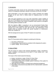
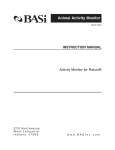
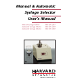
Manual & Automatic
Syringe Selector
User’s Manual
Manual Syringe Selector
Automatic Syringe Selector
Automatic Syringe Selector
MA1-59-7357
MA1-59-7358
MA1-59-7359
Publication 5401-002-REV- A
WEEE/RoHS Compliance Statement
EU Directives WEEE and RoHS
To Our Valued Customers:
We are committed to being a good corporate citizen. As part of that commitment,
we strive to maintain an environmentally conscious manufacturing operation. The
European Union (EU) has enacted two Directives, the first on product recycling
(Waste Electrical and Electronic Equipment, WEEE) and the second limiting the use
of certain substances (Restriction on the use of Hazardous Substances, RoHS).
Over time, these Directives will be implemented in the national laws of each EU
Member State.
Once the final national regulations have been put into place, recycling will be offered
for our products which are within the scope of the WEEE Directive. Products falling
under the scope of the WEEE Directive available for sale after August 13, 2005 will
be identified with a “wheelie bin” symbol.
Two Categories of products covered by the WEEE Directive are currently exempt
from the RoHS Directive – Category 8, medical devices (with the exception of
implanted or infected products) and Category 9, monitoring and control instruments.
Most of our products fall into either Category 8 or 9 and are currently exempt from
the RoHS Directive. We will continue to monitor the application of the RoHS
Directive to its products and will comply with any changes as they apply.
• Do Not Dispose Product with Municipal Waste
• Special Collection/Disposal Required
Table of Contents
Harvard Apparatus Syringe Selector
1
SUBJECT
PAGE NO.
General Information - Warranty and Repairs ......................2
Specifications..........................................................................3
Introduction ............................................................................4
Theory of Operation ..............................................................4
Connections ............................................................................5
Fitting Instructions:
Cutting and Polishing ................................................6
Cleaning ....................................................................7
Fitting Assembly ........................................................7
Calculating Dead Volume:
Controlling the Syringe Selector with a Computer ......8
General Information
2
Harvard Apparatus Syringe Selector
Serial Numbers
All inquires concerning our product should refer to the serial number of the unit.
Serial numbers are located on the rear of the chassis.
Calibrations
All electrical apparatus is calibrated at rated voltage and frequency.While the flow
will stay calibrated, the peak will vary.
W a rr a n t y
Harvard Apparatus warranties this instrument for a period of two years from date of
purchase.At its option, Harvard Apparatus will repair or replace the unit if it is found
to be defective as to workmanship or material.
This warranty does not extend to damage resulting from misuse, neglect or abuse, normal wear and tear, or accident.
This warranty extends only to the original customer purchaser.
IN NO EVENT SHALL HARVARD APPARATUS BE LIABLE FOR INCIDENTAL OR CONSEQUENTIAL DAMAGES. Some states do not allow exclusion or limitation of incidental or consequential damages so the above limitation or
exclusion may not apply to you. THERE ARE NO IMPLIED WARRANTIES OF
MERCHANTABILITY, OR FITNESS FOR A PARTICULAR USE, OR OF
ANY OTHER NATURE. Some states do not allow this limitation on an implied warranty, so the above limitation may not apply to you.
If a defect arises within the two-year warranty period, promptly contact Harvard
Apparatus, Inc. 84 October Hill Road, Building 7, Holliston, Massachusetts
01746-1371 using our toll free number 1-800-272-2775. Goods will not be accepted
for return unless an RMA (returned materials authorization) number has been issued
by our customer service department. The customer is responsible for shipping
charges. Please allow a reasonable period of time for completion of repairs, replacement and return. If the unit is replaced, the replacement unit is covered only for the
remainder of the original warranty period dating from the purchase of the original
device.
This warranty gives you specific rights, and you may also have other rights which vary
from state to state.
R e p a i r F a c i l i t i e s a n d P a rt s
Harvard Apparatus stocks replacement and repair parts.When ordering, please
describe parts as completely as possible, preferably using our part numbers. If practical, enclose a sample or drawing.We offer a complete reconditioning service.
CAUTION
This pump is not registered with the FDA and is not for clinical use on human
patients.
Specifications
Harvard Apparatus Syringe Selector
3
Specifications
Switching Capacity
4 syringes
Port Diameter
0.020 in
Dead Volume:
Selected Side
Waste Side
at 10 µ l
at 30 µ l
Connection for the Port
Valco type ZDV connectors
Introduction
Harvard Apparatus Syringe Selector
4
Harvard Syringe Selectors are designed to switch the perfusion medium from one of
up to four syringes. The selected stream flows through a port connected to the animal while all non-selected syringes flow to a common waste port.
Up to 4 syringes may be connected to the Syringe Selector. If less than 4 ports are
required, the unused ports may be plugged.
The Automatic Syringe Selector is available in 110 VAC and 220 VAC models. Please
check to insure that both power supply and the model match.
The Automatic Syringe Selector is supplied with a computer interface, external control (remote control) and with a manual event control capacity. Using the computer
interface, it can be used in a fully automated manner.
Theory of Operation
Manual Use of the Automatic Syringe Selector
1. Plug the Syringe Selector into an appropriate power outlet and turn the
power switch on. The LED indicator light on the front panel will come on
indicating the position of the valve.
2. Press the control toggle switch momentarily toward HOME. If the valve is
not in position
1, it will realign to the position 1. If it is already aligned, it will not move.
As the valve moves towards HOME (position 1), it may sequence through
each position, allowing the possibility that sample may flow briefly through
each syringe into the
per-fusion outlet. Care must be taken to prevent
possible contamination.The best way to avoid this is to always perform operation #2 before before making any connections.
3. Make connections as required (See Connections Section).
4. To switch from one perfusion medium to the next, move the toggle switch
momentarily toward STEP and the valve will advance from position 1 to position 2. Pressing this switch again will advance it one more step.
Port 1 is located at the 12 ’O Clock position. The valve rotates counter clockwise. Therefore the 9 ’O Clock position is the port 2 where syringe 2 must
be connected.
Ports 1, 2, 3 and 4 are 90° apart. The drain port is nearest to the actuator
handle/motor.The outlet is nearest to the spring.
Connections
Harvard Apparatus Syringe Selector
5
In order to insure flexibility, the Syringe Selector is designed with ports which accommodate the standard 1/16 inch tubing. Any 0.300 inch or longer Valco type nut and
ferrule assembly can be used to attach 1/16 inch tubing in the port (see Fitting
Instructions). This offers endless connection possibilities using various off-the-shelf
hardware and flexibility in connection materials. The following are some suggestions
how the Syringe Selector may be connected in a microdialysis system.
U s i n g t h e S t a n d a rd 2 3 G a u g e C o n n e c t o r s
Connections can be made using the supplied 1/16 inch, 23 gauge Reducing Adapters.
The 1/16 inch side is inserted in the port with the ferrule and the nut, and using a
wrench the ferrule is permanently clamped to the 1/16 inch side. (A finger tight nut
can be used as an alternative to the supplied steel nut and ferrule assembly.) This
makes a removable connector adapter.
Otherwise, the other end of the adapter (23 gauge side) can be connected to the CMA
blue connectors to accommodate the Teflon connecting tubes. When using the
Harvard Fused Silica Tubes, a 23 gauge adapter can be used to make a connection.
U s i n g t h e P E E K o r S t a i n l e s s S t e e l 1 / 1 6 i n c h Tu b i n g
A 1/16 inch PEEK or Stainless Steel tube may be used for connection. The smallest
inside diameter available of these tubes is generally 0.005 inch or 125 µm. PEEK tubing connections offer chemically inert contact to the passing fluid. Further reduction
in the inner diameter of these tubes can be achieved by using fused silica connections. A 1/16 inch Fused Silica Connector Adaptor can be used to connect to a fused
silica connecting tube.
O t h e r A l t e rn i t i v e s
Fused Silica Connecting Tubes can be connected directly to the port using a Valco
fused silica connection adapter. However, if the switch flow path is not rinsed properly after each used, the port may be permanently damaged due to a clogged or broken fused silica adapter in the port.
The Valco-type Zero Dead Volume Fitting is comprised of four parts: a female zero volume fitting detail, a male nut, a ferrule, and a length of tubing (see Figure 1). Since the
leak-tightness and integrity of the fitting is dependent upon tubing preparation and
proper assembly, this section addresses those two topics.
Fitting Instructions
Harvard Apparatus Syringe Selector
6
The Valco-type Zero Dead Volume Fitting is comprised of four parts: a female zero volume fitting detail, a male nut, a ferrule, and a length of tubing (see Figure 1). Since the
leak-tightness and integrity of the fitting is dependent upon tubing preparation and
proper assembly, this section addresses those two topics.
Tube
Nut
Ferrule
Fitting Detail
Pilot
Cutting and Polishing
Since the tubing is an integral part of the fitting, it must be properly prepared if the
entire fitting is to function as designed. To insure trouble-free service,Valco suggests
using their electrolytically pre-cut and polished tubing in stainless steel,electroformed
nickel, Nickel 200, Hastalloy C, or other materials.
If other tubing is to be used, make certain that all tubing ends are cut square with the
tube axis, and that both the ID and the OD are thoroughly deburred.
Will Leak
Will Not Leak
Next, inspect the end of the tubing where the ferrule will seat for scratches along its
length (Figure 2). Visible scratches along the tubing where the ferrule will seat are
not acceptable, but those behind the front edge of the ferrule will not interfere with
the integrity or the fitting. Minor scratches can often be eliminated by folding a small
piece of fine emery cloth or wet-or-dry sandpaper (200 to 400 grit) around the end
of the tubing and rolling the tubing between two fingers. This leaves concentric axial
lines in the area where the ferrule seats, which, while not ideal, are less likely to cause
a leak than longitudinal scratches.
NOTE: Electropolishing is generally not successful as a repair for bad tubing,
as it often simply rounds off the edges of a scratch without removing it.
Fitting Instructions
7
Harvard Apparatus Syringe Selector
Cleaning
After it has been polished, the tubing must be cleaned to remove residual metal shavings and grit from the sandpaper. This is best accomplished by using a syringe or
pipette to force a solvent such as methyl or isopropyl alcohol or acetone through the
tubing and then drying it with clean, dry compressed air or carrier gas.
Fitting Assembly
1. Slide the nut and ferrule onto the tubing in the order shown in Figure 1.
2. Insert the assembly into the fitting detail, screwing the nut in two or three
times by hand.
3. Push the tubing all the way forward into the detail so that it seats firmly. This
is essential for a proper zero dead volume connection.
4. Manually turn the nut into the detail until it is finger tight.
5. Using the appropriate open end wrench, turn the nut 1/4 turn (90°) past
the point where the ferrule first starts to grab the tubing. Fittings larger than
1/8 inch will require more than 1/4 turn (as much as 120°). The amount of
force required can vary considerably due to the friction between the nut and
the threads and the composition and wall thickness of the tubing being
used. Because of these variables a torque specification is unreliable.
6. Remove the fitting and inspect it. When made up properly, the ferrule may
be free to spin axially on the tubing, but should have no lateral movement
along the tubing. If the ferrule moves laterally, reinstall the fitting into the
detail and tighten it another 1/8 turn past finger tight.
7. Remove, reinspect, and repeat if necessary.
Once made up correctly, this Zero Dead Volume detail can be remade many times
without loss of integrity. Approximately 1/8 tun (45°) past finger tight is adequate for
most fittings. If additional torque is required, increase in increments of 1/16 turn.
The switching time (time required for motor to move one step forward) is approximately 1 second. No matter what type of connecting tubes are used, it is advisable
that the dead volume should be kept to a minimum. Minimizing the dead volume,
especially at all the joints would reduce the time it takes for alternative perfusion
medium to reach the probe tip.
Calculating Dead Volume
Harvard Apparatus Syringe Selector
8
The dead volume can be calculated by adding volumes of all the tubes in a flow path.
A syringe selector has a dead volume of approximately 10 µl. Therefore it should be
ensured that all the reducing adapters are fully inserted.
Precautions should be taken to insure proper flow switching that the flow should
equilibriate before switching. Usually a 5 to 10 minute wait is sufficient after connecting the new syringe for flow equilibration.
A higher than expected time may be observed for fluid to reach the animal after
switching the syringe if there is a pressure buildup in the system. After the initial setup
this can be tested by using carbachol in the switched perfusion medium which
induces a behavioral seizure as soon as it reaches the probe. If the time interval for
the fluid is more than expected, pressurizing the waste port (connecting an equal
length of the same connecting tube as the selected outlet side on the waste port)
would eliminate this problem.
C o n t ro l l i n g t h e S y r i n g e S e l e c t o r w i t h a C o m p u t e r
The easiest way of achieving a completely automatic operation is by using a Serial
Interfacing Device (optional), which allows control of up to two fluid selectors and up
to four Valco type electrically actuated HPLC valves using a PC.
However, there are alternatives to the PC control of the device. The actuator part can
be operated with many kind of relays, open collector transistors, BCD or logic level signal outputs or an RS-232 connector.
If you wish to control the Syringe Selector with other means than manual or the serial interfacing device, please request the technical notes on electronic circuitry of the
switch.