1
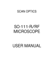
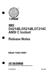
IPD Vision Appliances iLabel] Software User’s Manual 405-00011-00 Rev 1450 3 May 2007 iLabel Software User’s Manual Document Number 405-00011-00 Revision 1450; 3 May 2007 CopyrightE 2007–2006 DALSA Corporation CopyrightE 2005–2003 Coreco Imaging, Inc. All rights reserved. Printed in the United States of America. All copyrights in this manual, and the hardware and software described in it, are the exclusive property of DALSA Corporation and its licensors. Claim of copyright does not imply waiver of DALSA Corporation or its licensor’s other rights in the work. See the following Notice of Proprietary Rights. NOTICE OF PROPRIETARY RIGHTS This manual and the related hardware and software are confidential trade secrets and the property of DALSA Corporation and its licensors. Use, examination, reproduction, copying, transfer and/or disclosure to others of all or any part of this manual and the related documentation are prohibited except with the express written consent of DALSA Corporation. The information in this document is subject to change without notice. DALSA Corporation makes no representations or warranties with respect to the contents of this manual and specifically disclaims any implied warranties of merchantability or fitness for a particular purpose. DALSA Corporation assumes no responsibility for errors or omissions in this document. iLabel, iNspect, and the DALSA logo are trademarks of DALSA Corporation. All other trademarks are the property of their respective owners. DALSA IPD Email: [email protected] http://www.goipd.com IPD Headquarters 700 Technology Park Drive Billerica, MA, USA 01821 Tel 1.978.670.2002 Fax 1.978.670.2010 405-00011-00 iLabel User’s Manual PREFACE About This Manual This manual describes the iLabel software. This software is supported by the VA1x, VA2x, VA3x, VA4x Vision Appliances, and can also be installed and run, with a software license key, on a PC. This manual documents using the software on all platforms. Some features do not apply to all platforms. The vertical bars are “change bars” and mark additions or changes from the previous version of this manual. Table of Contents The iLabel Application . . . . . . . . . . . . . . . . . . . . . . . . . . . . . . . . . . . . . . . . . . . . . . . . . . . Creating an Inspection Solution . . . . . . . . . . . . . . . . . . . . . . . . . . . . . . . . . . . . . . . . Using Multiple Cameras . . . . . . . . . . . . . . . . . . . . . . . . . . . . . . . . . . . . . . . . . . Using the Exposure Control . . . . . . . . . . . . . . . . . . . . . . . . . . . . . . . . . . . . . . . Using the Internal Timer . . . . . . . . . . . . . . . . . . . . . . . . . . . . . . . . . . . . . . . . . . Using Preprocessing . . . . . . . . . . . . . . . . . . . . . . . . . . . . . . . . . . . . . . . . . . . . . Available Preprocessors . . . . . . . . . . . . . . . . . . . . . . . . . . . . . . . . . . . . . . . . . . Inspection Area and Movement Area . . . . . . . . . . . . . . . . . . . . . . . . . . . . . . . . Additional Inspection Areas . . . . . . . . . . . . . . . . . . . . . . . . . . . . . . . . . . . . . . . Inspection Grid and Ignore Areas . . . . . . . . . . . . . . . . . . . . . . . . . . . . . . . . . . . Reference Areas . . . . . . . . . . . . . . . . . . . . . . . . . . . . . . . . . . . . . . . . . . . . . . . . “Stop On” Conditions . . . . . . . . . . . . . . . . . . . . . . . . . . . . . . . . . . . . . . . . . . . . Using Decision Delay . . . . . . . . . . . . . . . . . . . . . . . . . . . . . . . . . . . . . . . . . . . . Adjusting the Decision Delay . . . . . . . . . . . . . . . . . . . . . . . . . . . . . . . . . . . . . . Create Condition . . . . . . . . . . . . . . . . . . . . . . . . . . . . . . . . . . . . . . . . . . . . . . . . Select or Define New Strings . . . . . . . . . . . . . . . . . . . . . . . . . . . . . . . . . . . . . . Select or Define New Destinations . . . . . . . . . . . . . . . . . . . . . . . . . . . . . . . . . . Create/Edit Equations . . . . . . . . . . . . . . . . . . . . . . . . . . . . . . . . . . . . . . . . . . . . Create New Function . . . . . . . . . . . . . . . . . . . . . . . . . . . . . . . . . . . . . . . . . . . . Free Edit . . . . . . . . . . . . . . . . . . . . . . . . . . . . . . . . . . . . . . . . . . . . . . . . . . . . . . Displayed Colors . . . . . . . . . . . . . . . . . . . . . . . . . . . . . . . . . . . . . . . . . . . . . . . . Review History . . . . . . . . . . . . . . . . . . . . . . . . . . . . . . . . . . . . . . . . . . . . . . . . . Performance Tips . . . . . . . . . . . . . . . . . . . . . . . . . . . . . . . . . . . . . . . . . . . . . . . . . . . . System Administration and Password Protection . . . . . . . . . . . . . . . . . . . . . . . . . . . 1 1 4 4 4 5 6 8 9 9 11 15 18 19 22 23 24 25 27 28 31 32 35 36 Rev 1450; 3 May 2007 iii iLabel User’s Manual 405-00011-00 iCollect . . . . . . . . . . . . . . . . . . . . . . . . . . . . . . . . . . . . . . . . . . . . . . . . . . . . . . . Viewing Data Output . . . . . . . . . . . . . . . . . . . . . . . . . . . . . . . . . . . . . . . . . . . . . . . . . HyperTerminal . . . . . . . . . . . . . . . . . . . . . . . . . . . . . . . . . . . . . . . . . . . . . . . . . History Log . . . . . . . . . . . . . . . . . . . . . . . . . . . . . . . . . . . . . . . . . . . . . . . . . . . . Monitoring VA15/VA20/VA30 from the Network . . . . . . . . . . . . . . . . . . . . . . . . . . Network Commands . . . . . . . . . . . . . . . . . . . . . . . . . . . . . . . . . . . . . . . . . . . . . . . . . Supported Commands . . . . . . . . . . . . . . . . . . . . . . . . . . . . . . . . . . . . . . . . . . . . Using Remote Monitor (VA21/VA31/VA4x) . . . . . . . . . . . . . . . . . . . . . . . . . . . . . . Glossary . . . . . . . . . . . . . . . . . . . . . . . . . . . . . . . . . . . . . . . . . . . . . . . . . . . . . . . . . . . . . . . 37 38 38 39 40 41 41 42 43 List of Tables VA2x & VA3x Input Reassignments . . . . . . . . . . . . . . . . . . . . . . . . . . . . . . . . . . . . . . . . VA4x Input Reassignments . . . . . . . . . . . . . . . . . . . . . . . . . . . . . . . . . . . . . . . . . . . . . . . iv 34 34 Rev 1450; 3 May 2007 405-00011-00 iLabel User’s Manual List of Figures The iLabel Application Window . . . . . . . . . . . . . . . . . . . . . . . . . . . . . . . . . . . . . . . . . . . Select Solution Panel . . . . . . . . . . . . . . . . . . . . . . . . . . . . . . . . . . . . . . . . . . . . . . . . . . . . Sensor Setup Panel . . . . . . . . . . . . . . . . . . . . . . . . . . . . . . . . . . . . . . . . . . . . . . . . . . . . . Preprocessing Setup Panel . . . . . . . . . . . . . . . . . . . . . . . . . . . . . . . . . . . . . . . . . . . . . . . . iLabel Setup Panel . . . . . . . . . . . . . . . . . . . . . . . . . . . . . . . . . . . . . . . . . . . . . . . . . . . . . . Inspection Area Setup Panel . . . . . . . . . . . . . . . . . . . . . . . . . . . . . . . . . . . . . . . . . . . . . . Inspection Areas . . . . . . . . . . . . . . . . . . . . . . . . . . . . . . . . . . . . . . . . . . . . . . . . . . . . . . . Inspection Area Settings . . . . . . . . . . . . . . . . . . . . . . . . . . . . . . . . . . . . . . . . . . . . . . . . . Reference Examples . . . . . . . . . . . . . . . . . . . . . . . . . . . . . . . . . . . . . . . . . . . . . . . . . . . . Barcode Setup Panel . . . . . . . . . . . . . . . . . . . . . . . . . . . . . . . . . . . . . . . . . . . . . . . . . . . . OCR Setup Panel . . . . . . . . . . . . . . . . . . . . . . . . . . . . . . . . . . . . . . . . . . . . . . . . . . . . . . . Learn Images Panel . . . . . . . . . . . . . . . . . . . . . . . . . . . . . . . . . . . . . . . . . . . . . . . . . . . . . Decision Panel . . . . . . . . . . . . . . . . . . . . . . . . . . . . . . . . . . . . . . . . . . . . . . . . . . . . . . . . . Outputs Panel . . . . . . . . . . . . . . . . . . . . . . . . . . . . . . . . . . . . . . . . . . . . . . . . . . . . . . . . . . Rejector Setup Panel . . . . . . . . . . . . . . . . . . . . . . . . . . . . . . . . . . . . . . . . . . . . . . . . . . . . Rejector Function . . . . . . . . . . . . . . . . . . . . . . . . . . . . . . . . . . . . . . . . . . . . . . . . . . . . . . Conditional Output Panel . . . . . . . . . . . . . . . . . . . . . . . . . . . . . . . . . . . . . . . . . . . . . . . . Create/Edit Condition Panel . . . . . . . . . . . . . . . . . . . . . . . . . . . . . . . . . . . . . . . . . . . . . . Create/Edit Output String . . . . . . . . . . . . . . . . . . . . . . . . . . . . . . . . . . . . . . . . . . . . . . . . Create/Edit Destination . . . . . . . . . . . . . . . . . . . . . . . . . . . . . . . . . . . . . . . . . . . . . . . . . . Create/Edit Equations . . . . . . . . . . . . . . . . . . . . . . . . . . . . . . . . . . . . . . . . . . . . . . . . . . . Add New Function . . . . . . . . . . . . . . . . . . . . . . . . . . . . . . . . . . . . . . . . . . . . . . . . . . . . . . Free Edit Window . . . . . . . . . . . . . . . . . . . . . . . . . . . . . . . . . . . . . . . . . . . . . . . . . . . . . . Ready to Run . . . . . . . . . . . . . . . . . . . . . . . . . . . . . . . . . . . . . . . . . . . . . . . . . . . . . . . . . . Monitor Panel . . . . . . . . . . . . . . . . . . . . . . . . . . . . . . . . . . . . . . . . . . . . . . . . . . . . . . . . . History Recall . . . . . . . . . . . . . . . . . . . . . . . . . . . . . . . . . . . . . . . . . . . . . . . . . . . . . . . . . Save or Export Solution Panel . . . . . . . . . . . . . . . . . . . . . . . . . . . . . . . . . . . . . . . . . . . . . System Administration Panel . . . . . . . . . . . . . . . . . . . . . . . . . . . . . . . . . . . . . . . . . . . . . iCollect Panel . . . . . . . . . . . . . . . . . . . . . . . . . . . . . . . . . . . . . . . . . . . . . . . . . . . . . . . . . . History Log Page . . . . . . . . . . . . . . . . . . . . . . . . . . . . . . . . . . . . . . . . . . . . . . . . . . . . . . . Monitor Window . . . . . . . . . . . . . . . . . . . . . . . . . . . . . . . . . . . . . . . . . . . . . . . . . . . . . . . Rev 1450; 3 May 2007 1 2 3 5 7 8 9 10 11 12 13 14 15 16 17 18 21 22 23 24 25 27 28 29 30 32 33 36 37 39 40 v iLabel User’s Manual vi 405-00011-00 Rev 1450; 3 May 2007 405-00011-00 iLabel User’s Manual THE ILABEL APPLICATION Creating an Inspection Solution 1. Launch iLabel If iLabel is not already running, open the Application window now. Each screen has two panels. The left panel is for Control and Navigation, with the Action Buttons. The right panel is the Work Area, and displays the camera image. These two panels are always present in the application window, but most of the following figures show only one panel. Control & Navigation Image & Work Area The iLabel Application Window The Info button at the bottom of each panel gives help information on the panel options. You can also navigate through Help using hyperlinks, the Table of Contents, Index, or Search. The Ok button at the bottom of each panel exits the panel and goes back or up one level. The Close button (first panel only) closes the iLabel application. The VA15/VA20/VA30 continues inspecting; VA21/VA31/VA4x halts inspecting. Rev 1450; 3 May 2007 1 iLabel User’s Manual 405-00011-00 2. Start a Solution a. Click on the “Select Solution” button. b. Since you are defining a new Solution, click the “Start New Solution” button. If you had an existing Solution configured, this action would overwrite it. The software will initialize, exit the screen, and go back up one level. Current Solution ID number. Start creating a new Solution (application) and overwrite any existing Solution in the Appliance memory. Initializes the software and exits this panel. Load a Solution saved in Appliance memory at the selected ID number. Solutions can be saved with ID numbers for quick change over. Disable switching while you edit a Solution. Enter an ID number to store a Solution. Solutions are loaded with index numbers, for quick change over. Number range 0–1023. Load a Solution (previously saved) from this PC or the network, into Appliance memory. Progress Bar Initialize the appliance and exit this panel. Select Solution Panel On the VA15/VA20, up to 150 Solutions are stored in the Appliance memory. On the VA30 up to 1024 Solutions. The number of Solutions depends on image size and Solution complexity. On the VA21/VA31/VA4x or a PC, Solutions are stored on the hard drive; usually in \iNspect\Solutions\iLabel. You can store more Solutions in a different directory, and import them. 3. Set up a Solution In the Setup panel, only the Sensor button is active. This step must be completed before any of the other panels can be accessed. If you had loaded a previously saved Solution, all of the buttons would be active. a. Click on the “Sensor” button to access the Setup Sensor panel. 2 Rev 1450; 3 May 2007 405-00011-00 iLabel User’s Manual 4. Set up the Sensor Here you can set up the sensor input trigger and associated image settings. If you are using a conveyer or other moving parts, set up the trigger delay, exposure and brightness with moving parts. a. Complete the Sensor Setup, then click “Ok.” With the Sensor Setup completed, a check appears next to the “Sensor” button, and the “iLabel” button is now active. Select the type or number of cameras: Single – one monochrome camera. Multiple – up to 3 monochrome cameras. Virtual – 3 images from 1 camera. Select the current or active camera (if multiple). Select what causes the Appliance to snap an image: Internal Timer – the slider sets the Appliance clock, and the time between images. Inspection Trigger – an external signal from a photosensor or a relay. Click the box to enable the slider, to set a delay between when the object is under the trigger sensor and when the object is under the camera. Define the duration (width) of a pulse and offset (delay) after a trigger input, for controlling a light. If you have a monitor connected directly to the VA15, VA20/VA30 select how often the display is updated: use Continuous for focusing, None for fastest operation. You can adjust the sensor settings to get the best image. Invert reverses black and white, or makes the image a negative. Select optional image pre-processing. Click OK when you are finished, to exit this panel. Sensor Setup Panel Once you have clicked on a slider, you can also use your keyboard’s arrow keys to step the slider up or down. The Vision Appliance supports programmable Exposure, Brightness and Contrast. Not all cameras support these features. Rev 1450; 3 May 2007 3 iLabel User’s Manual 405-00011-00 Using Multiple Cameras NOTE If you are using multiple cameras in your inspection, it is important to understand that the sensor settings are common to all 3 camera inputs. As a result, changing the exposure, for example, on camera 1, will affect cameras 2 and 3 also. Complete the Solution configuration and learning, for one camera, then return to the Setup panel to select another camera. You are directed to the Setup Sensor panel to focus the camera. The image area displays a live image when you enter the Setup Sensor panel. Focus the camera and click “Ok” and continue configuring and learning the Solution for the camera. The camera view can not be changed in every panel. The selection is grayed out in some panels. Using the Exposure Control The Exposure setting indicates the approximate exposure time. The slider range changes to match the programmable range of the camera. For fast moving parts, you must have a very low exposure, and a very bright light source. Refer to the Appliance User’s Reference Manual, Appendix B for information on motion, blur, and calculating exposure. NOTE The time between external triggers, or the internal timer setting, must be larger than the Exposure Time plus the Image Acquire Time (frame time) plus the Trigger Delay. The Exposure setting will override the internal timer setting if this condition is not met. (Trigger Rate or Internal Timer ) > (exposure + frame time + trigger delay) Using the Internal Timer If you are using the internal timer, and processing a complex application, you may need to increase the Sensor Trigger slider to avoid skipping parts. It is sometimes a good idea to start with a slow time during setup, say 100 ms, and then optimize it when the application is complete. First save your Solution with the internal timer set to the longer inspection time, then go back and try adjusting the time to a smaller interval. Notice the Parts Skipped counter on the Monitor panel. 4 Rev 1450; 3 May 2007 405-00011-00 iLabel User’s Manual Using Preprocessing Preprocessing is optional, not a requirement. Preprocessing changes the image to enhance objects; for example, edge or contrast enhancement. You can enable up to five preprocessors for each camera view. With multiple cameras, there is one common enable, but each camera has its own preprocessing setup. You can configure different preprocessors on each camera view. You can enable proprocessing for all cameras, but you do not have to select and configure preprocessors on each camera. You can leave one or more cameras with no preprocessors selected. a. Click “Ok” to exit this panel when you have finished configuring preprocessing. Shows the active camera. Go back to the Sensor Setup panel to change the camera view. Enable/Disable preprocessing on all camera views. Use the list boxes to select preprocessing operations. Click ROI to create a rectangle to appliy processing to. Click “Parameters” to display or change values. Not all preprocessors have values you can change. Clear a box to disable a single preprocessor. You do not have to delete the preprocessor and its values to temporarily disable a preprocessor. Enter coefficient values for 3x3 or 5x5 filters. Enter new values for preprocessing parameters, and click Apply to accept your changes. Exit this panel and go back one level. Preprocessing Setup Panel NOTE Preprocessing is performed as the image is acquired and transferred to memory. All images displayed or saved will show the result of preprocessing. Rev 1450; 3 May 2007 5 iLabel User’s Manual 405-00011-00 Available Preprocessors 3x3 – general 3x3 convolution. Enter 9 coefficient values. Parameter: Divisor. All 9 pixels are multiplied by the corresponding coefficients, summed, then divided by Divisor. The center pixel is replaced by the result. 5x5 – general 5x5 convolution. Enter 25 coefficient values. Parameter: Divisor. All 25 pixels are multiplied by the corresponding coefficients, summed, then divided by Divisor. The center pixel is replaced by the result. Dice – Draw a grid of lines (1 pixel thick) of value Value, spaced Dx horizontaly and Dy vertically. Parameters: Dx, Dy, Value. Dilate – Simple thickening or 3x3 dilation. Bright lines become thicker (dilated). Parameter: Execution times, number of iterations performed. Range 1 to 10. Erode – Simple thinning or 3x3 erosion. Bright lines become thinner (eroded). Parameter: Execution times, number of iterations performed. Range 1 to 10. HFlip – Mirror or flip about the horizontal axis. Parameters: none. VFlip – Mirror or flip about the vertical axis. Parameters: none. Invert – Reverse black and white, by subtracting each pixel value from 255. Parameters: none. Laplace – Edge enhancement, 3x3 filter. Parameters: none. Median – 3x3 Median filter, sorts the values of 9 neighbors and replaces with the median value. Parameters: none. Roberts – Edge enhancement, filter. Parameters: none. Sharpen – Edge enhancement, 3x3 filter. Parameters: none. Smooth – Moving average or low-pass, 3x3 filter; for removing noise or spurious values. Parameter: Execution times, number of iterations performed. Range 1 to 10. SobelX – Vertical edge enhancement, 3x3 filter. Parameters: none. Sobel XY – Horizontal and vertical edge enhancement, 3x3 filter. Parameters: none. SobelY – Horizontal edge enhancement, 3x3 filter. Parameters: none. Threshold – All pixels below Threshold are changed to Low Value. All pixels equal to or above Threshold are changed to High Value. Parameters: Threshold, Low Value, High Value. Range 0 to 255. Roughness – Intensity variability enhancement. Programmable filter size: 3x3 to 64x64, Gain range 1 to 16. 6 Rev 1450; 3 May 2007 405-00011-00 iLabel User’s Manual 5. Set up the Inspection a. Click on the “iLabel” button. b. Place a product with a good (or perfect) label in front of the camera, in the location where your inspection parts will appear, or a series of good parts moving past the camera. c. Click on “Take a Picture” and look at the still image. You will use this image to set up your inspection and tolerances. First, take a picture of the label. You want a “still” or “frozen” picture of a good label or even a “perfect” label to set up your inspection. Set up the inspection area and search area for the label. Set up the barcode reader if you need to read a product barcode. Set up the character reader if needed. Finally, you train on several good examples of your label. Exit this panel and go back one level. iLabel Setup Panel Rev 1450; 3 May 2007 7 iLabel User’s Manual 405-00011-00 6. Set up the Inspection Area a. Click on the “Inspection Area Settings” button. In the Inspection Area Setup, you tell the appliance what area to inspect, and how much the position of inspected labels vary. The more labels vary in position, the more time it takes to locate them before inspecting. If possible, minimize package movement with good fixturing. Inspection Area and Movement Area Two large boxes are displayed in the middle of the image area. The outside box is the Movement Area, or search area. The inside box is the Inspection Area, or the label area. See following page. b. Adjust the inside box (Inspection Area) to enclose the area of the label you are inspecting. During the Learning process, iLabel will identify two unique objects in Inspect Area 0 as “landmarks” (also called registration marks, or fiducials) for finding the Label position. You want some clearly focused, unique objects in Inspect Area 0. Click to add additional, smaller Inspection Areas, for sections of closer or finer inspection. Clear the check box to disable Reference Area, or leave checked to use the Reference Areas. Select Horizontal or Vertical edges for reference. Select for a Light Background and dark package edges Clear box for Dark Background and light package. Use the slider to adjust the noise threshold. Enable or disable the search area. Define how much the label is allowed to rotate, or how much rotation causes a failure. Click on the solid circle/button, and drag it around the outer circle. You can also use the arrow keys. Define how much the label is allowed to move, or how much movement causes a failure. Reject the label if the movement or offset is larger than the number of pixels entered. Exit this panel and go back one level. Inspection Area Setup Panel 8 Rev 1450; 3 May 2007 405-00011-00 iLabel User’s Manual Movement Area outside box Inspection Area inside box Reference Area 1 Reference Area 2 Inspection Areas c. Adjust the outside box (Movement Area) to enclose the area where the label is allowed to appear. The Movement Area must be at least 8 pixels wider and taller on each side of the Inspection Area. A variable speed line, or an inaccurate trigger can create a large variation in the label position. Additional Inspection Areas Additional Inspection Areas are optional. d. Click on “Add Inspection Areas” to add additional smaller inspection areas inside the Movement Area. These additional inspections may be smaller, and will use a smaller grid, or a finer inspection. The Locate or Search process is related to Inspection Area 0 only. The additional inspection areas do not add additional Locate time. Additional Inspection Areas can be deleted. Inspection Area 0 (the first area) cannot be deleted. Overlapping areas will be inspected by both Inspection Areas and both grids. Inspection Grid and Ignore Areas e. Right-click on the outline of the Inspection Area. Select “Show Grid” in the pop-up. A blue grid appears in the Inspection Area. When you “Show Grid” for one Inspection Area, all other Inspection Areas disappear temporarily. The area of blue rectangles is inspected and the area of pink rectangles is ignored during learning or training and during inspecting. You want to ignore areas that vary or change on your label, like dates, lot codes, or punch-outs. The ignored areas must be inside the Inspection Area (label). Ignored areas are not applied when searching for the label (Locate, Search or find). Rev 1450; 3 May 2007 9 iLabel User’s Manual 405-00011-00 • Left-Click on individual rectangles, or slowly drag to select multiple rectangles in a line, or a rectangle. Best results may be obtained by dragging down or right. • Double-Left-Click to select the entire grid. • Right-Click on individual rectangles or drag to de-select. • Double-Right-Click to de-select the entire grid. f. Right-click on the outline of the Inspection Area. Select “Hide Grid” in the pop-up. g. Right-click on the outline of the Inspection Area. Select “Settings”. You can change the Locator type (Auto/Manual) change the name or “tag” for the Inspection Area, change the acceptable change in pixel intensity, and change the acceptable defect area (at inspection time). Click OK to accept your changes, or click Cancel to cancel your changes. Automatic – iLabel software identifies two unique targets for finding the label in the search or movement area. Manual – you can drag the two green rectangles onto two unique targets for finding the label in the movement area. Type a new name for the Inspection Area. Define how much the pixel intensity is allowed to change between images, during training, learn, or Teach time. Add the sample to the learned images if the difference is above this value. Define how much the pixel intensity is allowed to change between images, during inspection time. Define what percent of the total Inspection Area (minus the ignored area) is allowed, or how much unrecognized area causes a failure. Accept or cancel changes to these settings. Inspection Area Settings 10 Rev 1450; 3 May 2007 405-00011-00 iLabel User’s Manual Reference Areas Setting up Reference Areas is optional. h. The Enable box is checked by default. Clear this box if you do not have two package edges in the image area, or you do not wish to use the Reference Areas. Two narrow rectangles are displayed on the right and left sides of the image area. Drag these rectangles onto the outer edges of your package (not the label) so the Appliance can track the position of your package before searching for the label and measuring the displacement or angle of the label. This method allows compensating for the movement of the package. i. Click on Vertical and drag the two rectangles to the right and left edges of your package; or click on Horizontal and drag the two rectangles to the top and bottom edges of your package. j. Change the height and width to enclose only a straight edge. Do not enclose curves, angles or tapered areas. Avoid the edges of the Label. See the examples below. k. Increase the rectangles widths out to the edges of the Image Area. l. Click “Ok” to return to the Setup iLabel panel. Vertical Edges label label label Horizontal Edges label wide package label camera or package at 90 degrees Reference Examples Rev 1450; 3 May 2007 11 iLabel User’s Manual 405-00011-00 7. Set up Barcode Readings a. Click the “Barcode Setup“ button. Click the box beside “Enable Barcode Reading”. b. Drag the box to enclose part or all of the barcode. There must be white space before and after the code, at least as wide as the thickest bar. You do not have to enclose the full height of the barcode. The barcode does not have to be inside the Inspection Area. You can use barcode reading to verify the code is always the same, and report errors only. Or, you can use barcode to read the value of changing codes, and report every read value. You can pre-select the barcode type, or let iLabel auto-detect the code type. c. Complete the barcode settings and click “Read” to test your settings. d. Click “Ok” to return to the Setup iLabel panel. Click to enable the barcode reader. Change to relaxed or advanced read algorithm. Set the time out for degraded codes. Select the background value. Select the direction of the barcode on the label. Drag the solid circle around the outer circle. Enable or disable testing a checksum for validation. Increase value to ignore artifacts or fuzzy edges. If you know the type of barcode, use the list box to select the correct type. Use Auto Detect if you know the code but not the type. This box displays the barcode type found if you used Auto Detect. Click Read to test your settings. The barcode value read is displayed below the button. Click Clear if the value was wrong, and adjust your settings. Compare to the displayed code, and fail if it does not match. Exit this panel and go back one level. Barcode Setup Panel If the barcode is applied separate from the label, you will have to enclose a larger area, to allow for movement of the code, similar to the movement area of the label. 12 Rev 1450; 3 May 2007 405-00011-00 iLabel User’s Manual 8. Set up Character Reading (OCR) a. Click on the “OCR Setup” button. b. Click “Add OCR Area” to create a rectangle in the Image Area. Drag and resize the rectangle to enclose a line of characters (horizontal or vertical). The contents appear in the Edit Window (in the OCR Setup panel). You can zoom in on this Edit Window. c. Resize the rectangle in the Edit Window to enclose a single character. Click ‘”Add Character” and enter the name or value of the character. Click “Ok” and the character and value appear in the Character Window (in the OCR Setup panel). d. Increasing sensitivity (“score”) will reject more “near” or “close” matches. e. If all characters are the same size, drag the rectangle in the Edit Window to the next character and click “Add Character” again. If the characters are different sizes, clear the box beside “Fixed size characters”, to resize and drag the rectangle in the Edit Window. f. The characters are added to the Solution file when you click “Ok” to exit this panel. Click on Add OCR Area to enable this panel. Then move the rectangle in the Image Area to enclose the characters you wish to read. Change the tag or name of the OCR area. Enter the string value if known. Fail if the string does not match this value. If no value is entered, report all values read and fail if unable to read. Adjust the tolerance for character matching. Open another image, in the Edit Window, to train on other character samples. Edit Window Resize the rectangle to contain a single character. Edit Window zoom controls. Open a file of characters. Save characters to a file. Add the character enclosed in the rectangle, and assign a tag or character value. Character Window Clear the box if the characters are different sizes. Clear the box if the character spacing is not constant or uniform. Click to select or deselect characters. Sort characters, edit value tag, delete selected or all. Number of characters trained. Add characters to the Solution file, exit this panel. OCR Setup Panel Rev 1450; 3 May 2007 13 iLabel User’s Manual 405-00011-00 9. Learn Label Images a. Click on the “Learn!” button. b. Select the “Percent of Acceptable Label Variation” and get ready to present or show several examples of good labels, or products with labels, to the Vision Appliance. c. Click on “Learn Good Parts.” iLabel first uses the still image to build a model of how it sees your label. The build process may take a couple of minutes to complete, depending upon the complexity of the label being inspected. NOTE During this learning process, the rejection mechanism should be disconnected. d. When the status changes to “Built” iLabel is ready to learn the range of acceptable labels from multiple samples. Start showing more parts to the camera. If you are triggering externally, such as from a conveyer belt, start the conveyer but disable the rejection mechanism. Small red boxes appear on the label during this process. These are differences. Add the sample to the learned images if the difference is above this value. Train on the still image, then on a series of good labels. You must present several labels so iLabel can learn the range of acceptable variations. This progress bar shows when iLabel has built the initial model of your label. The text on the right changes from “not built” to “built”. This window shows the progress of learning from multiple labels. The black wavy line should start out above the red solid line, then settle out to below the red line. Clear the Appliance memory of learned images and variations. Exit this panel and go back one level. Learn Images Panel 14 Rev 1450; 3 May 2007 405-00011-00 iLabel User’s Manual e. When the wavy black line in the “Percent of Label Variation” stops traveling above the red horizontal line, you can click on “Stop Learning” then click “Ok” to exit this panel. 10. Setup Decision Logic a. Click on the “Decision” button. In the Decision Setup panel, you define what action to take in the event that parts are skipped as a result of insufficient time allocated to the processor. Refer to page 4 “Using the Internal Timer” and page 35 “Performance Tips”. b. Click “Ok” to return to the Setup panel. Change camera view, if multiple. What to do when the target number or quota of parts are passed. What to do when a large number of images are failed. “Continuous” means one after the other, or failures “in a row”. What to do with images that are “skipped” “dropped” or “missed”. If images or labels are coming faster than it takes to Search and Inspect, some images will be missed. Assign the two VA40/VA41 Decision Outputs. Not available on the VA1x/VA2x/VA3x. Exit this panel and go back one level. Decision Panel “Stop On” Conditions The Appliance stops immediately when the Stop On count is reached. A Remote or Client display may show 1 or 2 less than the stop count because the Appliance stopped before the Client was updated. The Local or Server display (attached to the Appliance) shows the correct count. Rev 1450; 3 May 2007 15 iLabel User’s Manual 405-00011-00 11. Set Up Outputs a. Click on the “Outputs” button. In this panel, you can Enable or Disable saving images and data in the Appliance memory (History Log) or images to the hard drive (Image Log to file). You can set the pulse duration of the Pass, Recycle, and Reject signals, and you can set a delay between the end of processing and the output of these pulses. Enable “Conditional Outputs” to send data strings to the Serial Port or Ethernet. Enable or disable saving history logs to the appliance memory. for each category: Pass, Reject, Recycle. Number of records depends on image size. Enable or disable saving a number of camera images to the hard drive. Select SubFolders if you select more than one category (Pass/Recycle/Reject). Define if the output signals occur immediately, or after a signal from a sensor. Use the Rejector Setup button to adjust the delay. The button is not active if the decision output is immediate. Not supported on the VA15. Define the duration (pulse width) of the decision output signals. Use the arrows and changes take effect immediately. Or type a number and click Apply to accept your change. Enable Conditional Outputs to define and enable output to the Serial Port or Ethernet. The Setup button is not active if Disable is selected. Add an equation or an expression for communicating with a defined PLC or external logic device. Add and configure a PLC or external logic device. Exit this panel and go back one level. Outputs Panel “Image Log to file” will create a directory (if it does not exist) and will save camera images (not results or graphics) for the active or selected camera, to file names using sequential numbers (image0.bmp, image1.bmp etc.) when the solution is running. If you check “multiple” images from all cameras are saved. The image count will wrap around and start overwriting when the limit number is reached. To disable Image Log to file, you must return to this panel, clear the Enable check box under Image Log to file, and exit this panel (Ok). If you select more than one category, select “SubFolders” to separate the pass, recycle, and fail images. 16 Rev 1450; 3 May 2007 405-00011-00 iLabel User’s Manual 12. Set Up Rejector Timing If you are using the appliance to control the final movement of parts on your line, click on “Rejector Setup”. If it is not active, click beside Decision Sensor, then Click Rejector Setup. Rejector Timing does not operate if you are in Internal Timing mode. You must be using an Inspection Trigger and a Decision Sensor to use the Rejector timing. This feature is not supported on the VA15. The VA15 does not support a decision sensor input. The appliance stops processing whenever you enter this panel. Enter a number in the “Reject Rate” box. Enter 1 to reject every part, enter 2 to reject every other part, etc. The default is 0, to reject no parts (pass all parts). Click “Apply” to start the decision output. Use the slider to adjust the delay between the part in place (for rejection) sensor and the actuation of the rejector pulse. Status is stopped. No labels are inspected. No decisions are made on labels. Use the sliders to adjust the amount of delay after a signal from a sensor. The sensor would indicate the part is in place to be rejected. Enter a number, then click Apply to begin rejecting parts. Adjust the slider so the rejector activates at the correct time. The VA2x/VA3x has one slider, to set a single delay for all 3 decision outputs. VA40/VA41 has two sliders, to set delays for the two assignable Decision Outputs. Exit this panel and resume previous run state. Rejector Setup Panel If you have a “kicker” you want to make sure the kicker hits the part in the middle, and cleanly moves it off the line. If you have a flipper or track changer, you want a change at the last instant just before the product moves onto the new track, and not hit or disrupt the part. If you have a Rev 1450; 3 May 2007 17 iLabel User’s Manual 405-00011-00 marker, you want to get your mark in the middle of the label, not partially off the edge of the label. Please refer to the following discussion and instructions. Using Decision Delay The Rejector is a delay mechanism controlling the Pass, Recycle and Fail signal pulses output on the rear panel I/O. The intended purpose of the rejector is to remove defective parts from the production line at the correct point in time. The rejector can operate in two modes: “Immediate” and “Decision Sensor”. Immediate mode is intended for configurations where the outputs will be the input to another device such as a PLC (Programmable Logic Controller) that will schedule the rejection of the part. If no PLC is to be used, Decision Sensor mode allows for scheduling the rejector output to remove the defective part as shown in the following illustration. Decision Delay Timer 5 Pass Decision Table 5 Pass 6 Recycle 7 Fail 8 Pass Inspection Trigger Decision Sensor Part-inPlace Sensor Inspection Sensor Part-inPlace Sensor Inspection Trigger Delay Fail Recycle Pass Rejector Trigger Decision Tagged 10 9 4 Fail 8 Processing Time 7 6 Kicker 5 4 3 2 1 Decision Delay Rejector Function The illustration shows a typical rejector setup using the decision sensor. If immediate mode had been selected, input from the Rejector Trigger would be ignored and the outputs would activate immediately upon a decision being available. The Rejection Delay is the time it takes for the part to move from the decision sensor (Part-in-Place Sensor) to the device that will kick the part off the line. This time interval must be predictable and constant. The time value is input to iLabel from the Rejector Setup panel, accessed from the Setup Outputs panel. 18 Rev 1450; 3 May 2007 405-00011-00 iLabel User’s Manual Adjusting the Decision Delay a. Go to the “Setup Outputs” panel. b. Select the “Decision Sensor” radio button in the “Decision Output” section. c. Click the “Rejector Setup” button. This will open the Rejector Setup panel. Here you can adjust and test the “decision delay” for the Decision Outputs. There is one active slider for the VA2x/VA3x. There are two active sliders 0 and 1 for the VA4x. The decision delay is the time from the decision trigger to when the part arrives at the kicker or rejector mechanism. This is shown in the previous illustration. If “Inspection trigger” was selected (VA4x only) the delay is the time from the acquisition trigger to when the part arrives at the rejector mechanism. d. Set the Reject Rate for your rejector test. For example if you set this to 1, every part passing the rejector trigger will result in the Reject output pulse. Every part will be rejected. Entering 2 will reject every other part. Click Apply to start the decision output. Adjust the Decision Delay to a value that properly rejects the parts at the rejection frequency selected. Caution: When adjusting the Decision Delay, allow the rejector to resynchronize with the parts, by allowing at least 1 part to pass between the rejector sensor and the kicking device; this is the current (old) decision delay. Also be aware that if parts are equally spaced, it is easy to make the error of adjusting the rejector so that it is off by 1 or more parts; rejecting the wrong part. Rev 1450; 3 May 2007 19 iLabel User’s Manual 405-00011-00 e. When you select “Ok” from the rejector setup panel, the line must be reset. To do this, you must know how many parts are between the Inspection Trigger part-in-place sensor and the Decision Trigger part-in-place sensor (parts 5 through 9 in the illustration). These parts will be Passed. The reject rate is reset to “0” when you exit this panel. Caution: If this value is not correct you will reject the wrong parts. The safest method (if possible) is to stop the transport and remove all parts between the two sensors, and leave the part count in the dialog box at “0”. f. Click “Restart”. g. Reconnect the Inspection Trigger input, and restart the product transport. The “testing” and rejection stops, and the appliance goes back to processing (if it was running) or paused for programming. NOTE 20 When you click the Reset Product Line button on the Monitor panel, you again tell the Appliance how many parts there are between the Inspection Trigger and the Rejection Trigger. These parts are “Passed”. Rev 1450; 3 May 2007 405-00011-00 iLabel User’s Manual 13. Set Up Reporting If you want to output results of each inspection to another device for control, logging or analysis, you will need to set up the reporting method. a. Click the Enable radio button under Conditional Outputs, and then click “Setup”. Here you select or define strings that are output by the Vision Appliance, conditions that cause strings to be output, and where (which port) the strings are output. When the Appliance is running and inspecting labels, if your condition is True, a string is sent (output). If you always want data output, enter any positive integer (1, 2, 3) in the “If Condition” field (always true). If your Condition is True, a string is sent. Click Create/Edit to edit a condition or to define your own Condition statement. Enter an integer if you always want output. The strings are referenced by names. Select a pre-defined string, or click Add/Edit to edit a string or define your own string. Select a pre-defined destination, or click Add/Edit to edit a destination or define your own destination. Click Add and Delete to change the list of Conditions, strings, and destinations in use. Port 5020 is the default output. see note below Exit this panel and go back one level. Conditional Output Panel NOTE Port 5020 is the default, with a pre-defined data format. Ports numbers 1024 and below, 5005, 5010, 5015, 5021, and 5022 are reserved and cannot be used. You may prefer to use Ports 5050 through 5099. NOTE To view data, you can set up a HyperTerminal session. This is described later in this manual. Refer to “Viewing Data Output” on page 38. Rev 1450; 3 May 2007 21 iLabel User’s Manual 405-00011-00 Create Condition b. In the Conditional Output panel, click on the “Create/Edit” button to edit the current condition, or create a new condition statement. You can type text in the Condition field, insert variables, constants and operators. The Result variable takes the integer values: 1=Pass, 2=Recycle, 3=Reject. Result makes a good condition. The Failed Area, Label Angle and Package Angle take floating-point numbers. c. Click “Ok” to return to the Conditional Output panel. Change camera view, if multiple. Click on a variable name, then click on Insert Variable to add it to the Condition statement. Click on the boolean and arithmetic operators to add them to your Condition statement. Type in a Constant (number) and click Insert to add it to the Condition statement. Your Condition Statement appears here. You can also type in this field. Click on Clear to empty the Condition statement field. Click on Evaluate Condition to see the current value of your condition to the right of this button. 0=False, 1=True. The decision outputs are pulsed. The General Purpose Outputs are held true or false. Exit this panel and go back one level. Create/Edit Condition Panel GPI refers to the General Purpose Inputs. If there is no Solution ID Switch connected to the VA4x I/O connector, the Change Solution input and Solution ID bits 0–4 may be used for general purpose inputs, GPI1 and GPI3–GPI7, in the conditional outputs and equations assignments. The VA15/VA2x/VA3x has four general purpose inputs, IN0–IN3. GPO refers to the General Purpose Outputs. The VA15/VA2x/VA3x has 4 outputs OUT0–OUT3. GPO3 is the “Ready” status output. There are 4 unused outputs available on the VA4x I/O Connector: GPO4–GPO7. 22 Rev 1450; 3 May 2007 405-00011-00 iLabel User’s Manual Insert a GPI or GPO, then change the index to the input or output you desire: for example, change GPO[0] to GPO[4]. Select or Define New Strings d. Click on the “Add/Edit” button that appears beside “Then Send” to define new strings, or use the drop-list to select a pre-defined string. Here you can select pre-defined strings or define your own strings. Strings are called by their String Names. Click “Add”, then use the Variables and Special Characters to create your string. The Format field defines how variables will appear in your output string. e. Click “Ok” to return to the Conditional Output panel. Change camera view, if multiple. Click Add to create a new string, or use the drop-list to select an existing string. Click on a variable name, then click on Format to change how the output value appears, then click “Insert Selected Variable” to add the variable to your string. Click on a special character and click “Insert” to add it to your string. The defined content of a string appears here. You can type commas and spaces in this field, to separate variables. The value of the variables will be substituted in your output string. The evaluated string value appears here. The number values are substituted for the variables you inserted in your string. Exit this panel and go back one level. Create/Edit Output String NOTE The list of application variables is empty if you have not run the inspection. The list is automatically populated for trained camera views. Variables for non-configured or not learned camera views, take zero values. Rev 1450; 3 May 2007 23 iLabel User’s Manual 405-00011-00 Select or Define New Destinations f. Click on the “Add/Edit” button that appears beside “to Destination” to define new destinations, or use the drop-list to select a pre-defined destination. You can select a pre-defined destination, or define your own destination. • Serial is the serial output port on the Vision Appliance. There is only one valid serial port. • TCP/IP is for the Ethernet Port. You define the role of the Vision Appliance as a Client or Server. Client means the appliance sends data to a network server. You must enter the IP Address of your server. Server means the appliance is a server, and computers request data from the appliance. Requests for data do not impact the inspection speed. Port 5020 is assigned by default. Port numbers 1024 and below, 5005, 5010, 5015, 5021 and 5022 are reserved. g. Click “Ok” to return to the Conditional Outputs panel. h. Click “Ok” to return to the Setup Outputs panel. Set the port settings for communications on the serial port. Click Apply or Restore Defaults. Define output on the Ethernet connection. If you choose Client, enter an IP Address destination. If you choose Server, your requesting devices should use the port number shown or one you enter. Click Add to add your new destination to the list. You can delete a destination by clicking on the destination and then clicking Delete. Exit this panel and go back one level. Create/Edit Destination 24 Rev 1450; 3 May 2007 405-00011-00 iLabel User’s Manual Create/Edit Equations i. Click the “Add/Del” button under “Variable Assignment Equations”. j. Click “Ok” to return to the Setup Outputs panel. Click “Ok” to return to the Setup panel. Equations allow you to communicate with PLC devices. You define a PLC device, then assign variables names to the register locations. You use Equations to read and write to the variable names and manipulate values. Variables created here can be used for Conditional Outputs. Change camera view, if multiple. Click on a variable name, then click on Insert Left or Insert Right to add the variable to the equation. Or, Click in a field then double-click on a variable. A deleted variable takes a zero value if referenced. Click on the boolean and arithmetic operators to add them to the right side of your equation. Type in a Constant (number) and click Insert to add it to the right side of your equation. Select a predefined function to use in your equation. Your IF condition appears in the first field Your THEN equation appears in the next 2 fields. Click to clear the IF condition. Click Evaluate to display the current value of the equation or assignment. 1 = TRUE, 0=FALSE. Click to clear the right side of the equation. Click to add the equation to the list below. Click on New Name, or type a new name. Select a function to edit. Create a new function. Your equations are evaluated in the order they appear in this list. Click on an equation, and use the up and down arrows to change its position. Click on an equation, then click Edit, or Del to delete. Open an editing window. Save equations to a text file, open a saved file. Exit this panel and go back one level. Create/Edit Equations You can also use Equations to calculate additional values from Application Variables (measured results). You can create equations that override the Decision Table, by using “PASS”, “RECYCLE”, and “FAIL” (must be all capitals). This would change the output signals (for Pass, Recycle and Reject) at the I/O Connector, but the Monitor panel is still driven by the Decision table. Rev 1450; 3 May 2007 25 iLabel User’s Manual 405-00011-00 You can delete Application Variables, or assign new values to the same names, in this panel. Once you delete an Application Variable (Failed Area, Angle Offset, Result) you cannot un-delete it. This affects this panel, Conditional Outputs, and the output signals, but does not affect the Decision Table and Monitor panel. A group of predefined mathematical functions and string functions are available for you to insert into your equations. First, click in one of the three equation fields, to select the field you want to add a function into. Then use the Function drop list to select the desired predefined function. Inputs and Outputs Expand the list, if available, or insert a GPI or GPO, then change the index to the input or output you desire: for example, change GPO[0] to GPO[4]. The Pass, Recycle, and Fail or Decision outputs are pulsed. The GPO are not pulsed. They are driven high or low. If { }Then GPO(4) = [Camera03.Result] !=1 makes GPO4 low when Camera 3 Passes, high when Camera 3 Recycles or Fails. NOTE: “If” field is blank, “GPO(4)” is in the left field. Click on “Result” under “Camera03” and click “Insert Right” then click “!=” and then type 1. GPO3 is defined as a “Ready” or “Running” status output. This may be reassigned in the equation editor. Inputs may also be reassigned to Solution ID bits by the “Maximum Number of Hardware Switchable Solutions” in the Save/Export Solution panel. Not supported by the VA15. The reassigned inputs will disappear from the Application Variables (AppVar) list. Result – the result of all measurements and all camera views. This result is sent to the decision I/O and other communications. Result has three values: 1=PASS, 2=RECYCLE, 3=REJECT. Result0 – the value of Result, before it is output. This allows equations to evaluate the result, before outputing a pass/recycle/fail result to the various mechanisms. SOLUTION – load the Solution ID equal to SOLUTION at the end of the current equation evaluation. For example, if SOLUTION=6, Solution 06 is loaded when the equation/statement is evaluated (if the condition is true). Global.FrameCount – number of frames acquired since the Solution was loaded or since the Statistics were reset. Global.SolutionPollRate – (Hz) If this variable is set to a non-zero value, The Solution ID bits are polled at a rate equal to the value of Global.SolutionPollRate, in Hertz. For example, if Global.SolutionPollRate = 5, the inputs are polled at 5 Hz or 200 ms. Global.SolutionIndex – a value added to the Solution ID input bits, when a change solution occurs. For example, if Global.SolutionIndex = 5 and the SLN(0–2) = 3, or SID=3, when a Solution change is triggered (by ACC or SolutionPollRate) Solution 08 is loaded. 26 Rev 1450; 3 May 2007 405-00011-00 iLabel User’s Manual Create New Function In the drop list under Manage Execution Order, there are two predefined functions: • Solution Initialize – executes right after a Solution loads. • Post Image Process – executes after inspection but before a decision output. You can also create three different types of new functions: • Periodic – executes at fixed time interval. • User defined – executes when called by another function or statement. Allows you to pass 1, 2 or 3 parameters. You cannot rename the parameters. • Delayed Event – called a defined interval after (a) image is acquired, or (b) end of processing. • Input State Change – executes when a GPI changes. Click the “New” button beside the Function drop list under Manage Execution Order, to open the New Function window. When finished defining a function, click “Add” to add your function to the drop list. The “Del” button beside “New” will delete your function and all the statements it contains. Add New Function Rev 1450; 3 May 2007 27 iLabel User’s Manual 405-00011-00 Free Edit The “Edit” button under Manage Execution Order loads the highlighted statement or equation into the 3 statement fields (condition, name assignment, equation) for editing. Click the “Free Edit” button to open a text edit window. All statements under the current function appear in this window. • Right-click in the window to get cut, copy, paste, and insert (functions, variables, operators). Your New Functions or User Functions will appear at the bottom of the list. You can also use right-click in the 3 statement fields. • Click “Cancel” to discard any changes you made in this window. Free Edit Window 28 Rev 1450; 3 May 2007 405-00011-00 iLabel User’s Manual 14. Ready to Start Processing a. Click on “Ready to Run Hit to Start” to start inspecting parts. The Appliance begins inspecting parts immediately and the button text changes. Also notice that the top of the panel turns Green, meaning the Appliance is processing or inspecting. Any other color means the Appliance is in a stop or pause state. b. Click “Ok” to return to the first panel. Change camera view, if multiple. The text on this button changes with the state of the Appliance and Solution. Ready to Run Rev 1450; 3 May 2007 29 iLabel User’s Manual 405-00011-00 15. Monitor Inspection Results a. Click on the “Monitor” button to see the results of inspecting. The counters should be changing. You can reset the counts at any time. You may not see the counts go to zero, but you will see them go to a smaller number. There is a small delay between clicking on the “Reset Statistics” button and the change in numbers. Resetting Statistics does not clear the History Log. In some cases, updating the display with images may affect the total inspection time. The Appliance may run faster if you disable the Image update by selecting “Data Only” or “Nothing” under Display in this panel. An Exclaimation Point may appear if there is a problem, for example with the rejector sensor. Click on this to display a message. Select camera view for Monitor and History Recall. Not visible if only one camera is configured/trained. Inspect Time (displayed) + 20 ms + client/network overhead = Total Inspection Time. Current measured values. If you are using a rejector sensor, this button is active, and allows you to pause the Appliance and tell it how many parts are on the line. Reset the counters on this panel. View the History Records for inspected labels. This button is not active if History Log was disabled in the Setup Outputs panel. Halt inspecting, processing, decisions and all outputs. Run the inspection once, or manually trigger. Define the contents of the Client Display: Image and Data, Data Only, or no display update.** Exit this panel and go back one level. Monitor Panel ** A display category may be inactive if you enabled “Image Log to file” in the Outputs panel. 30 Rev 1450; 3 May 2007 405-00011-00 NOTE iLabel User’s Manual When you click the Reset Product Line button on the Monitor panel, you must tell the Appliance how many parts there are between the Inspection Trigger and the Rejection Trigger. These parts are “Passed”. The Pass/Recycle/Reject lights (front panel of the Appliance) are latched after a decision, and stay latched until the next decision is available. Resetting the Statistics, or Resetting the Product Line, does not clear the History Log. There are 2 ways to clear the History: 1) go to Setup and make a change, 2) load a Solution. You can save the current Solution, go to Select Solution, and reload the current Solution. Displayed Colors In the Image Display area, the largest (aqua) box shows the search area, and a blue cross-hair shows the position of the center of of the original trained model image. The Green cross-hair shows the displaced center of the current label, and the blue box(es) is (are) the inspect area(s). The two green boxes represent unique areas identified by iLabel when building its model (landmark, registration, fiducial). These are used to find the displacement and angle. Small red boxes inside the inspection area indicate defective areas in the label. A yellow box is the Barcode reader area. An orange box is the OCR reader area. Rev 1450; 3 May 2007 31 iLabel User’s Manual 405-00011-00 Review History b. Click on the “History Recall” button if it is active. This button is not active if the History Log was disabled in the Setup Outputs panel. We recommend disabling the history log during actual inspection. The Camera view is selected in the Monitor panel. The History Recall displays (in the Monitor panel) the measured values or data. The Work Area displays the image for each part that was recorded. c. Click on “Back to Monitor” and note the “Inspect Time”. d. Click on “Ok” to return to the first panel. The Camera view is not available if only one camera has been trained or configured. The values for each inspected label. Select a category: Pass, Recycle, or Reject. Drag the small circle to select a Record Number to view. Records are stored in Appliance memory. Exit this panel and go back to the Monitor panel. Do Not switch the Solution ID using an external hardware switch when displaying the History Recall panel. Exit this panel and go back one level. History Recall NOTE: When you are viewing the History records, the Conditional Outputs and History Log are locked. No new images or data are added to the History Log and the Conditional Outputs. Processing does continue and Pass/Recycle/Reject outputs are still available (unless driven by equations). Conditional Output will repeat the last values before the History was locked. 32 Rev 1450; 3 May 2007 405-00011-00 iLabel User’s Manual 16. Save and/or Export your Solution a. Click on the “Save/Export Solution” button. b. Enter a Solution ID number, and enter a short description. c. Click on the “Save Solution” button. You should save your Solution before you try optimizing the inspection time settings. Solution ID 00 automatically runs each time you open iLabel, unless an external ID switch is connected. You may want to return to the Setup Sensor panel to adjust the Internal Timer. If the time is set too low, parts may be skipped (skipped parts follow the action defined in the Decision panel). Current Solution ID number Change the number of Solution ID input bits. Not supported on the VA15. Assign an ID number to the Solution: 0–1023. Solutions are saved with an index ID number, for quick change over. 0–7 on the VA15. Enter a Description that you will recognize. Save your solution to Appliance memory, at the selected Solution ID number. Select the current running solution, any one Solution, or all Solutions saved on this Appliance, to Delete. Select the current running solution, any one Solution, or all Solutions saved on this Appliance, to Export. Save your solution to your PC or a network device. You must save your solution to the Appliance index first, before you can export. On VA4x, Do not export to \iNspect\Solutions. This is the Appliance index, and these files are deleted when you select Delete Saved Solutions. Progress bars Exit this panel and go back one level. Save or Export Solution Panel On the VA15/VA20, up to 150 Solutions are stored in Appliance memory, depending on image size and Solution complexity. On the VA30 up to 1024 Solutions. On the VA21/ VA31/VA4x or a PC, Solutions are stored on the hard drive; usually in \iNspect\Solutions\iLabel. You can store more Solutions in a different directory. Rev 1450; 3 May 2007 33 iLabel User’s Manual 405-00011-00 You can Export (save) your Solution to your PC or to a network device. Exporting a Solution allows you to distribute it across multiple Appliances. “Current Solution” matches the Solution ID number displayed under the iLabel logo. The index number range is 0–1023. Increasing the Number of Hardware Switchable Solutions reassigns General Purpose Inputs to be used as Solution ID input bits. The inputs will disappear from the Application Variable (AppVar) list in the Conditional Outputs and Equations panels. Not supported on the VA15. The VA15 uses 3 Solution ID bits SLN(2–0) to select up to 8 Solutions (0 through 7). Default assignment operation IN0/Decision trigger IN3 IN2 IN1 SLN2 SLN1 SLN0 ACC/Change solution TRIG/Sensor trigger NOTE Reassigning inputs to support 128 Solutions compromises the Decision Trigger. Default assignment operation GPI2/Decision trigger GPI7/SLN4 GPI6/SLN3 GPI5/SLN2 GPI4SLN1 GPI3SLN0 GPI1/Change solution GPI0/Sensor trigger NOTE VA2x & VA3x Input Reassignments Max # Hardware Reassignment operation Pin number Switchable Solutions 128 SLN6 4 64 SLN5 5 32 SLN4 7 16 SLN3 8 8 SLN2 12 8 SLN1 11 8 SLN0 10 13 2 VA4x Input Reassignments Max # Hardware Reassignment operation Pin number Switchable Solutions 64 SLN5 3 32 SLN4 18 32 SLN3 5 32 SLN2 17 32 SLN1 4 32 SLN0 16 15 2 Reassigning inputs to support 64 Solutions compromises the Decision Trigger. 17. Close the Application Window If you are satisfied with your Solution and have saved it, you can return to the first panel and Click on Close to exit the iLabel application window. The VA15/VA20/VA30 Appliance continues inspecting when you close the remote or Client window (Network connection). The VA21/VA31/ VA4x Appliance stops inspecting parts when you close the application window from a keyboard and mouse attached to the VA21/VA31/VA4x Appliance, unless the Remote Server is running. 34 Rev 1450; 3 May 2007 405-00011-00 iLabel User’s Manual Performance Tips Your Vision Appliance is optimized for performance, but for very high-speed applications, it may be necessary to minimize inspection overheads, to prevent “part skipping”. This can happen if the inspection queue is full when a new part to inspect is detected. In most cases, this would not be a problem given that the Vision Appliance can capture new images as it processes and renders a result on a previous image. However, in the event that a part does get skipped, the Vision Appliance will track it and render a result based on user criteria. General guidelines for performance optimization 1. Fixture parts and orientation whenever possible. 2. Keep the Movement Area as small as possible. 3. Reduce the amount of information to be processed. Complex objects may require more processing time. 4. Turn off history recording when your inspection criteria is well defined. 5. Turn off image data to the local display if it is not needed (Monitor panel, Display options). In many applications it is a good idea to display failed images only. 6. If the internal timer setting, or the time between parts on the line, is less than the total inspection time, images may be dropped (resulting in missed inspections). The Total Inspection Time is: Inspect Time; plus (approximately) 20 ms for VA21/VA31/VA4x or 40 ms for VA15/VA20/VA30; plus client or network overhead. The Inspect Time is displayed on the Monitor panel. Rev 1450; 3 May 2007 35 iLabel User’s Manual 405-00011-00 System Administration and Password Protection To prevent others from changing your Solution, you can enter a password for your Appliance. Without the password, others can only access the Monitor screen, to view the Run screen only. The password limit is 6 to 15 characters. In the Setup panel, click on the “System Administration” button. Log in as the Administrator to make changes. You should change the default Administrator password. Click the “Enable” checkbox if you wish to enable user accounts, and requre a password each time Internet Explorer tries to access the Appliance. Clear the checkbox if you do not want to require logins. Anyone can view the Monitor panel with out logging in. Enter the Administrator password and click “Log In”. The button changes to “Log Out”. Automatically log out administrator if idle for this long. Click this checkbox if you wish to enable user accounts and logging in. Clear the check box to disable. Create a new User Account. Delete the selected User Account. Change a user account password. Import User Accounts information. Export User Accounts information. Select or Clear options for the selected User. Collect a log of system events. Not supported on the VA15. Exit this panel and go back one level. Does not log you out. System Administration Panel User name is limited to 31 characters maximum. Full Name is limited to 63 characters maximum. Passwords are limited to 6 characters minimum and 15 characters maximum. 36 Rev 1450; 3 May 2007 405-00011-00 NOTE iLabel User’s Manual The default password for the Administrator account is “ipdadmin”. It is your responsibility to change the Administrator password. This is an Application password for the iNspect and iLabel applications, not for Windows or the Vision System. iCollect The iCollect application creates a log of system events, and IP Addresses, on all appliances connected and enabled for iCollect. One host PC must be running the iCollect application. Not supported on the VA15. System events collected are: successful and failed log-in to iNspect or iLabel, Log out, Save Solution, Load Solution, Stop inspecting and Start inspecting. Enable logging system events. Enter the Network Name or IP Address of the system that will collect the Log Events. Default is the Appliance network name. Exit this panel and go back one level. iCollect Panel If the network connection is lost between the host and Appliance, the log will be stored locally until the connection is reestablished. The Appliance will synchronize the local log with the host when the connection is reestablished. Rev 1450; 3 May 2007 37 iLabel User’s Manual 405-00011-00 Viewing Data Output If you enabled Conditional Output, there are several ways to view data output. This section will describe using HyperTeminal, and using the History Log page. HyperTerminal If you enabled conditional output, and the Appliance is a Server, you can use HyperTerminal. You can use HyperTerminal for either Ethernet or Serial Port communication. a. Open a new HyperTerminal session, enter your area code, and click “Ok”. b. In “Connection Description” enter a name for the session, for example, “iLabel1”. c. For Ethernet: Enter the IP Address of the Appliance in the “Host Address” and enter the port number (appliance default is 5020). Select “TCP/IP(Winsock)” for the “Connect using”. For Serial Port: Select COM1 or COM2 (your PC serial port) for the “Connect using”. Change the Port Settings to match the values you set in the Add/Edit Destinations panel. Note: In some versions of HyperTerminal, you can enter all information in the “Connect To” menu. In some versions, you can only set the “Connect using” field and you will have to open the File–Properties menu for the IP Address and Port Number settings. d. Click “Ok”, and the data should immediately start scrolling in the HyperTerminal window. If not, double-check your port settings in HyperTerminal. If there is still no data, verify that a Solution is active and running, and conditional output is enabled in the Setup Outputs panel. 38 Rev 1450; 3 May 2007 405-00011-00 iLabel User’s Manual History Log If you enabled conditional output, and the Appliance is a Server, you can use: • the History Log link on the Appliance Home page (VA15/VA20/VA30). • the iOutputLog application (VA21/VA31/VA4x) a. On the Appliance home page, click on “History Log”, or double-click on “iOutputLog.exe”. b. On the History Log page, click the “Connect” button, then click the “Start Logging” button. c. Before you close or leave this page, click the “Stop Logging” button, then click the “Disconnect” button. History Log Page Rev 1450; 3 May 2007 39 iLabel User’s Manual 405-00011-00 Monitoring VA15/VA20/VA30 from the Network a. On the Vision Appliance Home Page (in Internet Explorer) click on “Monitor”. Only one person can access the Appliance at a time, whether the session is Monitor or full access. The Monitor Window is not password protected. Viewing History or resetting the production line is not available from the Monitor window. b. When finished, click on the “x” button in the top right corner to close the Monitor window. Close Internet Explorer to ensure access to the Appliance is released. This display shows “Data Only” in the image area. Monitor Window NOTE 40 The first time a PC opens this Monitor page, you will get a warning message about certificates and signatures. Click “Ok”. The Appliance is writing its OCX and support files into your System directory. A few seconds after the hourglass disappears, the iLabel Application Window will open. Rev 1450; 3 May 2007 405-00011-00 iLabel User’s Manual Network Commands You can issue commands to the Appliance over the TCP/IP network, to select or change the running Solution, or temporarily change the trigger mode. A Solution must be running. a. Open a new HyperTerminal session, enter your area code, and click “OK”. b. In “Connection Description” enter a name for the session, for example, “iLabelCMD”. c. In “Connect To” enter the IP Address of the Appliance in the “Host Address” and enter the port number 5021. Select “TCP/IP(Winsock)” for the “Connect using”. d. Type “help” (followed by Enter or Return) to display a list of the available commands. Supported Commands ss ## change the running Solution ID. The new solution must already be stored on the appliance. The running Solution will not change if the new ID is not a valid Solution. The displayed ID number changes in the Monitor panel, and other panels, but does not change on the Monitor Window (opened from the Appliance home page), until youclose and reopen the Monitor Window. ns get the number of solutions. sl get a list of the solution ID numbers in use (separated by commas). sdl get a list of descriptions for Solutions (separated by commas). sd ## get a description for the Solution ID number given. tm # changes the trigger mode. This is a manual or temporary change. The saved Solution setting is not changed, and if you navigate to the Sensor page, the trigger setting will revert to the original Solution’s setting. tm 2 = Internal Timer, tm 3 = External Sensor Trigger, tm 4 = Software Trigger. Note: In Software trigger mode, the Appliance frame grabber responds to both the external trigger and software trigger. If you do not have an external trigger, the acquisition will wait for your software trigger. If there is an external trigger present, the acquisition will respond to the trigger, and not wait for your software trigger. gen generate a software trigger. This is used after setting the temporary trigger mode to tm 4. eval “statement” evaluate a statement once. This can change values of arguments defined in the Equation Assignments panel, or create new arguments. Format [ON|OFF] enable or disable pre-formatted output on port 5022. A Solution must be running. start start or restart the inspection. stop stop or halt inspecting. reset # reset the production line with a specific number of parts between the two sensors. reset Statistics reset the counters for Pass/Recycle/Reject. Rev 1450; 3 May 2007 41 iLabel User’s Manual 405-00011-00 Using Remote Monitor (VA21/VA31/VA4x) Using remote monitor requires a separate PC, with the ipd iLabel software installed (either the Demo or the full version). The VA21/VA31/VA4x must be running the remote server connection software. You can view a window similar to the Monitor Panel, with most buttons disabled. You can change the data/image display options. Requirements a) Vision Appliance (VA21/VA31/VA4x) with latest version of ipd iLabel software (v1236 or later), b) one or more Solutions saved to the Appliance, c) a PC on the same network, with either Demo or full version of the iLabel software (v1236 or later). The Appliances and PC must use the same version. On the Vision Apppliance 1) Close the iNspect or iLabel application, if running. 2) Start the remote server software: Start – ipd iLabel – Remote Connection Server. iServer opens, running Solution 00 (iNspect or iLabel) that was last run on the Vision Appliance. 3) You can select a different Solution ID and click Change. You can enable local image display, and change the camera view. On the remote PC 4) Open Windows Explorer, and navigate to the iNspect/iLabel software directory, either: D:\IPD iL:abel, or D:\IPD iLabelDemo. 5) Double-click on iMonitor.bat. (or iOutputLog.exe) 6) In the “connect to” pop-up window, enter the IP address of your Vision Appliance. The iMonitor (or the Output Log) window opens, displaying the Solution running on your Vision Appliance. In the Output Log window, click on Connect, then click on Start Logging. To close, click on Stop Logging, then click on Disconnect. 7) Make sure you close the iMonitor or Output Log window on the PC, before closing the iServer window on the Vision Appliance. 42 Rev 1450; 3 May 2007 405-00011-00 iLabel User’s Manual GLOSSARY Camera – The camera contains a sensor that converts the pattern of light from the part into electrical signals that are sent to the Vision Appliance. The signals are digitized into an array of values called pixels and processed to perform the inspection. Current Solution – The saved solution that matches the Solution ID displayed under the iLabel logo in the Control panel. Decision Delay – Please see Rejection Delay. Field of View – The area that is seen by the camera. Hirose – The name of a company that manufactures connectors. A round 4-pin, 6-pin, or 12-pin connector used on many cameras. Inspection Trigger Delay – the time between when an object is in front of the presence detector, part-in-place sensor, or trigger pickup finding the object, and when the object is in front of the camera. Detector Camera direction of motion Inspection Trigger Delay Time LED – A “Light Emitting Diode” lights up when current passes through it. LEDs are often used as indicator lights (power on, etc.) or as a light source for inspection. Lens – The lens gathers the light from the part being inspected, and forms an image on the camera’s sensor. The proper lens allows you to see the field-of-view you want and to place the camera at a convenient working distance from the part. Lighting – In most cases you will need special lighting that ‘amplifies’ the elements of the part that you want to inspect and ‘attenuates’ elements that you don’t want to inspect. Proper lighting makes inspection faster and more accurate. Poor or inappropriate lighting is a major cause of failure in machine vision inspection systems. Rev 1450; 3 May 2007 43 iLabel User’s Manual 405-00011-00 Light Ring – a ring or circle of Light Emitting Diodes or other light sources in a circle. A light ring is usually placed around the camera lens, to light up the camera’s field of view. Pixel – abbreviation for “picture element”, a single “point” in a digitized image. Progressive Scan – a non-interlaced or single field camera that usually has an image size similar to the RS170 and CCIR standard. Lines are scanned sequentially, instead of the interlaced lines in the even/odd field method of broadcast standard RS170 and CCIR cameras Rejection Delay – The time between when an object is in front of the presence detector, part-inplace sensor, or trigger pickup finding the object, and when the object is in front of the rejector or “kicker”. Also called Decision Delay. Detector Kicker direction of motion Rejection Delay Time or Decision Delay Time ROI – “Region-Of-Interest” or a smaller area inside the image area. Staging – Staging holds the part to be inspected at a precise location in front of the Appliance’s camera so it can ‘see’ the part. Putting the part in a set and known location allows the Appliance to quickly find and inspect the part. You may need a Part-in-Place sensor that tells the Appliance when the part is in its place in front of the camera. Strobe – A light that gives an extremely short extremely bright flash. Strobe Lights were first developed to freeze fast moving objects for still photography on film. Photo-electric Sensor – A light-sensitive device that responds to a change in light, usually reflected light but sometimes direct light. These can be visible light or infrared light. 44 Rev 1450; 3 May 2007