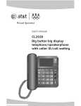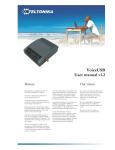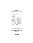
1
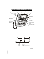
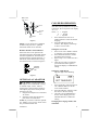
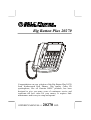
Big Button Plus 20270
CALLER ID SPEAKERPHONE
Congratulations on your selection of the Big Button Plus 20270
from Northwestern Bell Phones. This quality Caller ID
speakerphone, like all Genuine BELL® products, has been
designed to give you many years of continuous service and
represents the best value for your money. It requires little
maintenance and is easy to setup and operate.
OWNER’S MANUAL #
20270 ver.
IMPORTANT SERVICE INFORMATION
Read this manual before attempting to setup or use this instrument. It contains important
information regarding safe installation and use. Keep this manual for future reference.
Also save the carton, packing and proof of purchase to simplify and accelerate any needed
action.
WARNING
To prevent fire or shock hazard, do not expose this product to rain or any type of excess
moisture. If accidentally dropped into water, the AC adaptor should immediately be
unplugged from the wall along with the telephone line cord.
THIS SYMBOL IS INTENDED TO ALERT THE USER OF
THE PRESENCE OF IMPORTANT OPERATING AND
MAINTENANCE (SERVICING) INSTRUCTIONS IN THE
OWNER'S MANUAL.
Big Button Plus® 20270
CARTON CONTENTS
• Handset and Base Unit
• Handset Cord
• Long Telephone Line Cord
• Short Telephone Line Cord
• User’s Manual
• Warranty Card
1
010508A-1
SAVE THESE INSTRUCTION
IMPORTANT
SAFETY
INSTRUCTIONS
When using your telephone equipment, basic
safety precautions should always be
followed to reduce the risk of fire, electric
shock, and injury to persons, including the
following:
1. Read and understand all instructions.
2. Follow all warnings and instructions
marked on the product.
3. Unplug this product from the wall outlet
before cleaning. Do not use liquid
cleaners or aerosol cleaners. Use a
damp cloth for cleaning.
4. Do not use this product near water, for
example, near a bathtub, wash bowl,
kitchen sink, or laundry tub, in a wet
basement or near a swimming pool.
5. Do not place this product on an unstable
cart, stand, or table. The product may
fall, causing serious damage to the
product.
6. Slots and opening in the cabinet and the
back or bottom are provided for
ventilation, to protect it from
overheating. These openings should
never be blocked or covered. The
openings should never be blocked by
placing the product on the bed, sofa, rug,
or other similar surface. This product
should never be placed near or over a
radiator or heat register. This product
should not be placed in a built-in
installation unless proper ventilation is
provided.
7. This product should be operated only
from the type of power source indicated
on the marking label. If you are not
sure of the type of power supply to your
home, consult your dealer or local
power company.
8. Do not allow anything to rest on the
power cord. Do not locate this product
where the cord will be abused by
persons walking on it.
9. Do not overload wall outlets and
extension cords as this can result in the
risk of fire or electric shock.
010508A-1
10. Never push objects of any kind into this
product through cabinet slots as they
may touch dangerous voltage points or
short out parts that could result in a risk
of fire or electric shock. Never spill
liquid of any kind on the product.
11. To reduce the risk of electric shock, do
not disassemble this product, but take it
to a qualified service contractor when
some service or repair work is required.
Opening or removing covers may
expose you to dangerous voltages or
other risks. Incorrect reassembly can
cause electric shock when the appliance
is subsequently used.
12. Unplug this product from the wall outlet
and refer servicing to qualified service
personnel under the following
conditions:
A. When the power supply cord or
plug is damaged or frayed.
B. If liquid has been spilled into the
product.
C. If the product has been exposed to
rain or water.
D. If the product does not operate
normally by following the
operating instructions. Adjust
only those controls that are
covered by the operating
instructions. Improper
adjustments of other controls may
result in damage and will often
require extensive work by a
qualified technician to restore the
product to normal operation.
E. If the product has been dropped or
the cabinet has been damaged.
F. If the product exhibits a
distinctive change in performance.
13. Avoid using a telephone (other than a
cordless type) during an electrical storm.
There may be a remote risk of electric
shock from lightning.
14. Do not use the telephone to report a gas
leak in the vicinity of the leak.
SAVE THESE INSTRUCTIONS
MAINTENANCE
1.
Use a damp cloth to clean the plastic
cabinet. A mild soap will help to
remove grease or oil. Never use polish,
solvents, abrasives or strong detergents
2
2.
since these can damage the finish.
Your phone should be situated away
from heat sources such as radiators,
heaters, stoves or any other appliance
that produces heat.
INSTALLATION
PRECAUTIONS
1.
2.
3.
4.
Never install telephone wiring during a
lightning storm.
Never install telephone jacks in wet
locations unless the jack is specifically
designed for wet locations.
Never touch uninsulated telephone
wires or terminals unless the telephone
line has been disconnected at the
network interface.
Use caution when installing or
modifying telephone lines.
CAUTION
To reduce the risk of fire or injury to persons,
read and follow these instructions:
1.
2.
3.
4.
5.
6.
7.
3
Use only the battery(ies) specified in
this manual.
Do not dispose of the battery(ies) in a
fire. The cell may explode. Check with
local codes for possible special disposal
instructions.
Do not open or mutilate the battery(ies).
Released electrolyte is corrosive and
may cause damage to the eyes or skin.
It may be toxic if swallowed.
Exercise care in handling the battery(ies)
in order not to short the battery with
conducting material such as rings,
bracelets and keys. The battery or
conductor may overheat and cause
burns.
Do not attempt to recharge the
battery(ies) provided with or identified
for use with this product. The
battery(ies) may leak corrosive
electrolyte or explode.
Do not attempt to rejuvenate the
battery(ies) provided with or identified
for use with this product by heating
them. Sudden release of the battery
electrolyte may occur causing burns or
irritation to eyes or skin.
When replacing the batteries, all the
batteries should be replaced at the same
time. Mixing fresh and discharged
batteries could increase internal cell
pressure and rupture the discharged
batteries.
8. When inserting the battery(ies) into this
product, the proper polarity or direction
must be observed. Reverse insertion of
batteries can cause charging, and that
may result in leakage or explosion.
9. Remove the battery(ies) from this
product if the product will not be used
for a long period of time (several
months or more) since during this time
they could leak in the product.
10. Discard the “dead” battery (ies) as soon
as possible since “dead” batteries are
more likely to leak in a product.
11. Do not store this product, or the battery
(ies) provided with or identified for use
with this product, in high-temperature
areas. Batteries that are stored in a
freezer or refrigerator for the purpose of
extending shelf life should be stabilized
at room temperature prior to use after
cold storage.
12. Disconnect telephone lines before
installing batteries.
INDUSTRY CANADA
CERTIFIED
RINGER EQUIVALENCE NUMBER
NOTICE: The Ringer equivalence number
(REN) assigned to each terminal device
provides an indication of maximum number
of terminals allowed to be connected to a
telephone interface. The termination on an
interface may consist of any combination of
devices subject only to the requirement that
the sum of the ringer equivalence numbers of
all the devices does not exceed 5.
INDUSTRY CANADA NOTICE
NOTICE: The Industry Canada label
identifies certified equipment. This
certification means that the equipment
meets certain telecommunication
network protective, operational and
safety requirements. The Department
010508A-1
does not guarantee the equipment will
operate to the user’s satisfaction.
Before installing this equipment, users
should ensure that it is permissible to be
connected to the facilities of the local
telecommunications company.
The equipment must also be installed using
an approved method of connection. The
customer should be aware that compliance
with the above conditions may not prevent
degradation of service in some situations.
Repairs to certified equipment should be
made by an authorized Canadian
maintenance facility designated by the
supplier. Any repairs or alterations made by
the user to this equipment, or equipment
malfunctions, may give the
telecommunications company cause to
request the user to disconnect the equipment.
User should ensure for their own protection
that the electrical ground connections of the
power utility, telephone lines and internal
metallic water pipe system, if present, are
connected together. This precaution may be
particularly in rural areas.
CAUTION: User should not attempt to
make such connections themselves, but
should contact the appropriate electric
inspection authority, or electrician, as
appropriate.
010508A-1
4
Big Button Plus 20270 CONTROLS DIAGRAM
MEMO STORE
Button Button
DELETE
Button
OPTION
Button
C.BACK Visual Ring
Button
Indicator
REVIEW
DOWN Button
REVIEW
UP Button
CALLER ID SPEAKERPHONE
NEW CALL/MSG
LED Indicator
FLASH Button
Ringer ON/OFF
Switch
RE/PA Button
Emergency
Buttons
(Fire,Medial
&Police)
Tone/Pulse
Switch
Nor/Hi Receiver
Switch
SPEAKER Button
Speaker Phone
Volume Control
Base Unit
(Rear View)
LINE
LINE
JACK
DC
6V
DC 6V
JACK
DESCRIPTIONS
CALLER ID DISPLAY:
5
010508A-1
Alphanumeric Caller ID LCD panel A three-line LCD panel that displays:
• Real Time Clock
• Name /Phone Number of Caller
• Time /Date of Call
• New Call Indication
• Call Timer
• Repeat Call Indication
•
•
•
•
•
•
•
•
Off-Hook Indication
Blocked Call
Out of Area
Line Error
Call Back Function
Battery Low Indication
Message Waiting (if provided by
your local phone company)
Three Selectable Languages
(English, French, Spanish)
Call Back Button - Can automatically
call back the phone number of a person
which is selected from the caller ID
display.
Option - Allows you to change the
format of display of the phone number.
DELETE Button – Used to program or
deleting Caller ID records .
MESSAGE / New Call LED
Indicator - This LED flashes when you
have new message(s) from Message
Waiting (an optional service provided
by your local phone company) or when
there are new Caller ID call records
stored in memory. This LED turns off
when you have either retrieved your
message from Message Waiting, or if
you have reviewed your call records on
the Big Button Plus 20270.
Real time Clock Display -
010508A-1
The LCD panel will automatically set
and display the real time and day when
the first Caller ID call is received.
Review UP / Review DOWN Buttons Allows you to view the call history list
in either direction.
TELEPHONE UNIT:
FLASH Button - Momentarily hangs
up the phone to access custom calling
features such as Call Waiting or ThreeWay Calling provided by your local
phone company.
LCD BACKLIGHT AND LIGHTED
KEY PAD – The LCD and keypad
illuminates making for easy dialing even
in a darkened room.
Handset Retainer Tab - If you decide
to have the unit placed in the wall
mount position, the handset retainer tab
can be pulled out and turned around so
that it allows the handset to hang onto
the base unit.
RINGER ON/OFF Switch - Used to
turn the ringer volume ON or OFF.
HANDSET Receiver Volume Nor/Hi
Switch - Allows you to select the
handset receiver either Normal or High
volume.
Hook switch - A switch on the handset
cradle of the base unit, which is used to
hang up or get a dial tone.
Off -Hook Indication The LCD panel will display the OffHook icon “ ” on the first line of the
LCD panel to indicate that the handset is
Off-Hook .
One-Touch Memory Buttons - The
Big Button Plus 20270 can store up to 3
emergency telephone numbers into
memory (up to 16 digits each), and you
6
can then dial any of the stored phone
numbers by just pressing one of the
emergency buttons located above the
LCD panel.
the base unit. Carefully remove the
battery cover and follow the markings in
the compartment as shown below:
RE(REDIAL)/PA(PAUSE) Button This button allows you to automatically
dials the last phone number dialed up to
32 digits. Pressing the RE/PA button in
the dialing sequence will inserts a 4
seconds pause between dialed numbers.
(for use in PABX or long distance
services)
PULSE/TONE SWITCH - Located on
the rear of the base unit. It allows you
to switch the dialing mode to either
pulse or touch tone dialing.
TONE * Button - Used to temporarily
change the dialing mode from Pulse to
Tone when dialing in the Pulse mode.
Provides tone function to access special
services such as phone banking services.
SPEAKERPHONE Button - Allows
you to place and receive calls without
having to use the handset.
STORE Button - Used to store 10
phone numbers (up to 16 digits each) or
dial any of the stored phone numbers in
the 10 memory locations.
VOLUME Control - Used to adjust the
volume of the speaker when using the
speakerphone.
Wall
Mounting
Slots
Battery
Compartment
(Figure 1)
INSTALLATION
Desktop Use
1. Set the unit on the selected desktop
and connect the telephone line cord
to the telephone line jack on the rear
of the base unit.
2. Connect the opposite end of
telephone line cord to the
telephone modular wall jack.
3. Connect one end of the coiled
handset cord to the handset jack of
the base unit (located on the left
hand side of the base) and the other
end to the handset jack of the
handset.
Wall Use
(with a standard AT&T or GTE modular wall jack)
1.
Visual Ring Indicator - flashes to alert
a person who has trouble hearing that
the phone is ringing.
2.
BATTERY
INSTALLATION
3.
Your unit requires 4 “AA” batteries (not
included). alkaline batteries are
recommended. The battery
compartment is located in the bottom of
7
Connect the short telephone line
cord to the telephone line jack on
rear of the base unit.
Connect the opposite end of the
short telephone line cord to the
telephone modular wall jack.
Align the wall mounting slots with
the studs located on the modular
wall plate and slide the base down
to lock in place. See figure 1.
Telephone
Modular Wall
Jack
010508A-1
Base Unit
(Side View)
CALLER ID OPERATION
Studs
Modular
Wall
Plate
Wall Mount
slots
(Figure 1)
NOTE: If you do not have a standard
modular wall jack, have a qualified
technician mount one on the wall.
Handset Retainer Tab Installation
If the base unit is to be placed in the
wall mount position, the handset retainer
tab must be pulled out, turned around
and placed in the opposite direction, so
that the tab allows the handset to hang
onto the base unit, as shown in figure 2
Handset
Retainer
Tab
Setting the Language Mode
After the battery installation and power
connection, the LCD panel will display
“E F S”
where, E = English
F = French
S = Spanish
1. Press either the Review UP or
DOWN button to select the desired
language.
2. Press the DELETE button to
confirm , then display will change
to show “set area code.”
Setting the Area Code
1. Press review UP or DOWN button
to select the correct digit number.
2. Press DELETE button to confirm
and shift to the next digit.
3. Repeat steps 1-2 to set the next two
digits.
4. After the area code is completed,
press DELETE button again to
change the display to TIME/DATE
setting.
Setting the TIME/DATE
The first digit will be blinking
(Figure 2)
OPTIONAL AC ADAPTOR
CAUTION: Use only with Class 2
AC Adaptor (not included)with a rating
of 120VAC input, DC6V, 100 mA
output with a center tip that is negative.
The adaptor plug must correctly fit the
machine’s DC jack.
1. Plug the AC Adaptor into a standard
AC outlet.
2. Insert the small plug into the DC
jack on the rear of the base.
NOTE: If you wish to order the optional
AC Adaptor, an Accessory Order Form
has provided with this unit.
010508A-1
SET
TIME/DATE
SET TIME/DATE
1.
2.
3.
Press repeatedly either the Review
UP or DOWN button to set the
correct time and date.
Press the DELETE button to shift
the cursor to the next setting.
Once the correct TIME/DATE is
shown on the display, press the
DELETE button to confirm the
setting.
Changing the Language Mode, and
Time/Date
8
1.
2.
Press and hold the “DELETE”
button, then press the UP button.
The display will show “E F S".
Follow steps described in section
of Setting the Language Mode,
Area Code and TIME/DATE (Initial
Use).
Automatic Time/Date Stamping
Your Caller ID automatically sets the
Time & Date when a call is received
Receiving Caller ID Information
All incoming phone calls are stored in
the order in which they are received.
Make sure that the Call Identifier
Delivery (CID) service is being
provided on your telephone line by your
local phone company. When CID data
is sent, the Big Button Plus 20270 will
automatically capture and display the
information from the phone company.
NOTE: If you answer the telephone
before the second ring, the LCD panel
will not show Caller ID information.
• If the caller’s name and phone
number is available, the LCD panel
will display the information in the
format as shown :
•
•
•
•
9
If only the caller’s phone number is
available, the caller’s phone
number will be shown and the third
line of the LCD panel will show
“-----”.
If the caller’s name or phone
number is blocked by the sender,
the LCD panel will display
“BLOCKED CALL” on the third
line of the panel.
If the call is Out of Area, the LCD
panel will display “OUT OF
AREA” on the third line of the
panel.
•
When the Caller ID receives the
message waiting signal from your
local phone company, the
“MESSAGE WAITING” will be
displayed on the LCD panel for a
short time. “MSG” icon will flash
on the top line of the LCD and the
new call LED indicator will be
blinking.
• If the number received does not
have the same area code stored in
the Big Button Plus 20270, the
phone number will automatically
add “1” along with the area code &
phone number.
NOTE: The Message Waiting feature is
an optional service provided by your
local phone company. For more details
regarding definitions of terms, refer to
the Glossary section.
Clear Message Waiting Indicator
Press and hold the DELETE button,
followed by the review DOWN button
to clear the message waiting.
Reviewing Call Records
If you have received new calls, the New
Call LED indicator will blink and the
LCD panel will display the total number
of calls stored. A new call Counter is
located on the upper right hand corner of
the LCD panel to indicate the number of
new calls received.
Using the Review UP and Review
DOWN buttons
• Press the Review UP or Review
DOWN buttons to browse through
the call records. The most recent
call is displayed first on the LCD
panel.
NOTE: The LCD display will display
“END OF LIST” on the third line of the
LCD display indicating the ending of the
call history list is reached while using
the Review UP or DOWN button.
010508A-1
Automatic Call Back
Allows you to automatically dial the
number of the person who has called
previously, provided that Caller ID
information has been recorded.
1. Select the caller you want to call
back by pressing the Review UP or
Review DOWN button.
2. When the call record is displayed
during review lift the handset or
press the SPEAKERPHONE button.
Press the call back button. The
phone number displayed on the
LCD will be dialed automatically.
The LCD panel will show the IN
” and the talking
USE icon "
timer starts to count in 5 seconds.
NOTES:
• The Call Back feature will not dial
the phone number if the selected
Call Record phone number is
blocked or if it is not available.
OPTION Button
Each press of this button will change the
format of display as follow.
7 – digit --- 7digit phone number
10 – digit – 3 digit area code + 7 digit
phone number
11 – digit – long distance code “1” + 3
digit area code + 7 digit
phone number.
Erasing A Single Call Record
1. Press either the Review UP or
DOWN button to display the call
record to be erased.
2. Press quickly the DELETE button
twice. The display will show the
next caller ID record, after you have
deleted the call record.
NOTE: A call record cannot be
retrieved once it has been deleted.
Erasing All Call Records
1. Press either the Review UP or
DOWN button once to enter the call
010508A-1
2.
history list and to review all call
records.
While the last call record is
displayed. Press and hold the
DELETE button for at least five (5)
seconds until the LCD display
shows “NO CALL”.
LCD Panel Display Messages
Different messages are displayed on the
LCD panel to indicate the status of the
Caller ID.
TOTAL XX NEW XX
• While the caller ID is in standby
mode, it shows the count for the
total number of calls and new calls
received.
BLOCKED CALL
• In some areas, caller may be able to
block their name and phone number
from appearing on the Caller ID of
the receiving party. The LCD panel
will display “BLOCKED CALL”
on the last line of the LCD panel.
OUT OF AREA
• This is a call from an area where
Caller ID service is not yet offered
or an area that is not yet providing
Caller ID delivery via the long
distance network. The LCD panel
will display the “OUT OF AREA”
on the last line of the panel.
NEW CALL INDICATION
• If you have new calls to be
reviewed, the MESSAGE/New Call
LED Indicator on the unit will blink
and “NEW” will momentarily
appear on the upper right hand
corner of the panel. Once you have
reviewed all new call records and
message waiting messages,
MESSAGE/NEW CALL LED
indicator will turn off and the new
call counter will reset to "00".
$$TOLL ICON
• Appears on the upper left side of the
LCD screen when the incoming call
10
is a long distance call and the
service is provided by your local
phone company.
END OF LIST
• Indicates that the end of the call
history list is reached while using
the review UP and DOWN buttons.
REAL TIME CLOCK DISPLAY
• If the unit is in standby mode, the
display will show the current real
time clock, date, count for total
number of calls and new calls
received.
CALL TIMER
• If the unit is in OFF-HOOK state,
the display will show the IN
USE icon “ ” and start to count
the talking time about 5 seconds
later. The conversation time counts
up to 59 minutes and 59 seconds
when activated. The call timer stays
on approximately 3 seconds after
the conversation by pressing the
Hook Switch or returning the
handset to the base cradle.
LOW BATTERY WARNING
• The LCD panel will display the
Low Battery icon
“
” on the
LOW
first line of the LCD panel to
indicate that the AAA batteries are
below operating voltage.
• It is recommended to review all call
records before removing batteries.
REPEAT CALL INDICATION
• If an incoming call message has
been recorded previously, the LCD
panel will show “REPEAT”.
Only the most recent call record is
recorded in memory.
MESSAGE WAITING OR MSG
• If you have Message Waiting
messages stored in the mailbox
(provided by your local phone
company). Upon receiving the
Message Waiting message, the
“MSG WAITING” will be
displayed on the LCD panel for a
11
short time and the NEW CALL
LED Indicator will start to blink.
And “MSG” icon will display flash
on top of the LCD screen. Once you
have retrieved the messages, the
“MSG” icon will disappear from the
panel and the NEW CALL LED
indicator will turn off after all new
call messages have been reviewed.
Message Waiting Indication is not
yet supported in all areas.
LINE ERROR
On rare occasions, the Caller ID
information sent by the telephone
company may have an error in the
transmission. This is not the fault of
your Caller ID unit. It can only
capture and store the data that was
received.
• If a line error is detected in the
transmission, the LCD panel will
display “LINE ERROR ”.
TELEPHONE OPERATION
Dialing Mode (PULSE/TONE Switch)
• If your home is equipped with
touch-tone dialing service, set the
PULSE/TONE switch to TONE
position.
• If you have a pulse (rotary) dialing
service, set the PULSE/TONE
switch to PULSE position.
Pulse>Tone (Mixed Mode) Dialing
If you only have pulse (rotary dialing)
service in your area and want to access
tone dialing services, set the
TONE/PULSE switch to the PULSE
position. Dial the desired number and
when tone signals are required press the
TONE button once. Subsequent digits
will be dialed in tone mode. Dialing
will be reset to Pulse mode when
handset is returned on-hook.
Adjusting Speaker Volume
You can adjust the speaker volume
during conversation with the caller or
010508A-1
when you place a call, press the
SPEAKERPHONE button and listen for
a dial tone. Adjust the speaker volume
to a comfortable listening level.
Handset Volume Nor/Hi
Allows you to adjust handset receiver
audio level. Set the switch to Nor for
Normal or set Hi for High Volume.
Placing a Call
Lift the handset or press the
SPEAKERPHONE button and listen
for a dial tone. Dial the desired phone
number.
NOTE: If you do not hear a dial tone
after pressing the SPEAKERPHONE
button, adjust the VOLUME control
located on the right hand side of the Big
Button Plus 20270.
Receiving a Call
When the phone rings, lift the handset or
press the SPEAKERPHONE button, and
start conversation with the caller.
NOTE: If you cannot hear the caller,
adjust the VOLUME control to a desired
listening level. If the callers cannot hear
you, speak closer to the base unit.
Ending a Call
Upon completion of a call, you can hang
up the Big Button Plus 20270 by
returning the handset back into the
handset cradle on the base, or by
pressing the SPEAKERPHONE button
( if the speakerphone mode was initiated)
Last Number Redial
The last number redial feature may be
used to dial the last number called (up to
32 digits).
1. Pick up the handset or press the
SPEAKERPHONE button and listen
for a dial tone.
010508A-1
2. Depress the REDIAL button. The
phone number dialed last will be
dialed out automatically.
Flash
Pressing this button momentarily hangs
up the phone to access custom calling
features such as Call Waiting or ThreeWay Calling provided by your local
phone company. For other Custom
Calling features, refer to the instructions
provided by your local phone company.
Redial/Pause
When the line is busy hang up the
phone, then lift the handset press , press
this button will automatically dial the
last number called. Press this button to
insert a 4-second delay between dialed
numbers in PABX systems or long
distance services.
Using Memory Dial
You can store up to 13 frequently called
telephone numers(each up to 16 digits)
with your Big Button Plus 20270. Three
emergency numbers can be dialed at the
touch of a button and ten additional
numbers which can be accessed by using
the MEMO button.
NOTE: Telephone numbers can be
stored in the TONE or PULSE mode.
3.
4.
To Program the 3 Emergency
Numbers
1. Lift the handset and listen for a dial
tone.
2. Press and release STORE
BUTTON.
3. Enter the number to be stored. (The
telephone number will not dial out.)
4. Press and release the STORE
BUTTON.
5. Press the corresponding emergency
buttons for each of the emergency
numbers you wish to store:
12
telephone number will be dialed out
automatically.
(Fire)
(Hospital)
(Police)
6. Replace the handset to the base.
NOTE: If the line power is lost for a
few hours, phone numbers stored in
MEMORY are not lost. The Big Button
Plus 20270 will retain the programmed
numbers.
IMPORTANT: When programming
emergency numbers and/or making test
calls to emergency numbers:
1.
Remain on the line and briefly explain
to the dispatcher the reason for the call
before hanging up.
2.
Perform such activities during offpeak hours such as early morning or
late evening.
To Dial an Emergency Number
1. Lift the handset and listen for a dial
tone.
2. Press the desired button. The
number stored in that button's
memory location will be dialed.
To program 10 frequently called
phone numbers
1. Pick up the handset (or activate the
speakerphone).
2. Press and release the store button.
3. Enter the phone number (up to 16
digits).
4. Press and release the store button.
5. Press location number (0-9) where
you want to stored
6. To store more phone numbers or
modify existing numbers in memory,
repeat steps 1-5 .
Recalling Stored Numbers From Two
Touch Memory
1. Pick up the handset and listen for a
dial tone.
2. Press the MEMO button.
3. Press the corresponding memory
location key (0 - 9). The stored
13
Transfer and Store Phone Numbers
from an In-Coming Call (70 Calls) to
Memory Locations (01-10).
1. On-Hook state.
2. Press the Review UP or DOWN
button to select the desired call.
3. Press the STORE button.
4. Press the desired emergency button
or 10 two-touch memory locations.
5. To transfer and store more phone
numbers in memory, repeat steps
1-4.
NOTE: Number stored previously in
the selected location will be replaced by
the one recently stored. To prevent
number from being deleted accidentally.
You are advised to view the memory
location (01-10) record before storing
the number.
Viewing the Stored Number (onetouch)
1. On-Hook State.
2. Press the desired three emergency
numbers button.
3. The pre-stored phone number and
location number will display. If no
number was previously stored, the
display shows only the location
number.
Viewing the Stored Number (twotouch)
1. On-Hook State.
2. Press the MEMO button.
3. Press the desired location number
button (0-9).
4. The pre-stored phone number and
location number will display. If no
number was previously stored, the
display shows only the location
number.
GLOSSARY OF TERMS
010508A-1
Blocked Name/Number - In some areas,
callers may be able to block their name
and phone number from appearing on
the Caller ID LCD panel of the
receiving party.
Call Memory - A memory location
which holds the Caller ID call records.
The Big Button Plus 20270 can store up
to 70 Caller ID call records. If there are
more than 70 calls, only the 70 most
recent calls are recorded in memory.
Call Record - Caller ID information on
a single caller which is stored in the
Caller ID’s call memory.
Caller ID - A device that identifies the
calling party before you answer a call.
This device can be used to screen
unwanted calls and eliminate harassment
from annoying calls.
Message Waiting - An optional service
provided by your local telephone
company. This service allows the
calling party to leave messages without
requiring the user to have an answering
machine. Please check with your local
phone company regarding availability
and additional information regarding
Message Waiting service.
Out of Area Call - This is a call from
an area where Caller ID service is not
offered or an area that is not yet
providing CID delivery to your area via
the long distance network.
Ringer Equivalence Number (REN) A number located underneath the base
of your phone(s) or phone-related device.
The REN is used to determine how
many phones can be connected to the
same telephone line while still having all
those devices ring when you receive a
call. In most areas, but not all areas, the
REN total of all devices should not
exceed five (5). Call your local phone
company to determine the maximum
REN for your calling area.
Single Data Message Format (SDMF)
This Caller ID message format includes
the Caller’s Phone number, Date of call
and Time of call.
Multiple Data Message Format
(MDMF) - This Caller ID message
format includes the Caller’s Phone
number, Caller’s Name, Date of call and
Time of call.
TROUBLESHOOTING
010508A-1
14
CALLER ID UNIT TROUBLESHOOTING TABLE
SOLUTION
• Check the batteries for proper installation.
• If the batteries are weak or dead, replace with new batteries
The Caller ID
(alkaline batteries are recommended). Please refer to the
LCD panel is
“Battery Installation” section of the user’s manual for more
blank
details.
• Check the connection of the AC adaptor.
• The Caller ID unit will not function until you have Caller ID
service provided by your local phone company. Call your
local phone company to have Caller ID installed on your
telephone line.
• Check your telephone line connections. Refer to the section
“INSTALLATION” of the manual for details.
The Caller ID
• If you picked up the phone before the second ring, the caller
LCD panel does
information will not be correctly received. If you have a
not show the
telephone answering device (TAD) connected with the unit, set
caller’s name
the TAD to answer after two rings or more.
and/or phone
• If it is a blocked call or an out-of-area call, the caller’s name
number
and/or phone number will not appear on the display. Please
refer to the “Receiving Caller ID Information” section of the
user’s manual for more details.
• If only the caller’s phone number appears on the display, it
may
be a Single Data Message Format (SDMF) call, as opposed to a
Multiple Data Message Format (MDMF) call. Please refer to
the Glossary section of the user’s manual for definitions.
• On rare occasions, the Caller ID information sent by the
“LINE
telephone company may have an error in the transmission.
ERROR”
This is not the fault of your Caller ID unit. It can only capture
and store the data that was received.
• The DELETE button must be pressed twice briefly to delete a
Cannot delete
single call record. To delete all call records, press and hold the
call records in
DELETE button for as least 5 seconds. Please refer to the
memory
“ERASING A CALL/ALL CALLS” section of the manual for
more details.
• On rare occasions, Caller ID information sent by the telephone
company may be too weak to be detected by the Caller ID.
This is not the fault of the Caller ID unit; it can only capture
No Data Sent
and store the digital data that was received.
• This message also appears when the Caller’s local phone
company does not have Caller ID service available.
SYMPTOM
TELEPHONE UNIT TROUBLESHOOTING TABLE
15
010508A-1
SYMPTOM
•
No dial tone
•
•
•
•
•
Will not ring
•
•
Static
•
•
•
•
Cannot dial out
010508A-1
SOLUTION
The handset cord or telephone line cord may be loose at the
connections. Push in firmly at both ends to establish good
contacts.
Test the phone at a different telephone wall jack and listen for a
dial tone.
Test a different phone in the wall jack and listen for a dial tone.
Check the RINGER ON/OFF switch. It may be in the OFF
position.
The phone or another phone connected to the same line may be
in the off-hook (in-use) position. Place the phone in the onhook (hung-up) position to receive incoming calls.
Try a different phone; if the problem still exists, the fault is not
with the unit.
Look for the Ringer Equivalence Number (REN) number
Printed underneath your phone(s). Sum up the total REN
numbers for all the phones or answering machines connected to
your telephone line. Your phone(s) may not ring if the REN
total exceeds five (5). Please call your local company to
determine the maximum REN for your calling area.
Try a different phone; if the problem still exists, the fault is not
with the unit.
Some atmospheric conditions such as very low humidity can
cause static build-up.
Are you in a rotary only area? Move the PULSE / TONE
Switch to PULSE.
Try a different phone in the jack. If the problem persists, the
fault is not in the Big Button Plus 20270.
Is the phone connected to an answering machine? Disconnect
the answering machine and try to have the phone plugged into
the jack alone. If it works alone, there is a compatibility
problem. Purchase a 2 for 1 adaptor at any phone or electrical
supply store. Plug the 2 for 1 adaptor into the modular wall
jack, then plug the phone into one side and the answering
machine on the other side of the adaptor.
16
20270/010508A-1
17
010508A-1