1
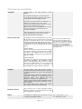
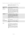
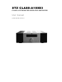
XTZ CLASS-A100D3
CLASS A INTEGRATED HIGH-END AMPLIFIER
User manual
© 2008 XTZ AB , www.xtz.se
Page: 1 / 14
Table of contents
Page:
Contents
3
About XTZ
4
Technical presentation
5
Preparations
6
Practice of sound / Installation and placement tips
7
Mounting
9
Functional reference
10
Technical specifications
13
Service & Support
14
Page: 2 / 14
Contents
Contents
Congratulations of your purchase of the CLASS
A100 D3.
CLASS A100D3 provides many possibilities, in
order to utilize this product in the best way, please
read the manual carefully before using Room
Analyzer. It takes patience to optimize a hifi
system. If you lack experience from this kind of
measurements or have any questions, please
contact our “free of charge” support.
(Support info on the last page of the user manual)
Read the manual before using the product and use
all possibilities carefully.
Page: 3 / 14
About XTZ
Philosophy
Our reference and starting point is to recreate a
natural sound, taking into account that acoustics
always is a matter of taste.
XTZ Goal
Our main goal is to provide the best value
for money.
Our concept:
- Cut down the numbers of middlemen
- Put more money into product quality
and less on advertising.
- Manufacture cost-effective in large volume
- Provide perfect technical solutions
Contakt
Website: www.xtz.se
E-mail: [email protected]
Page: 4 / 14
Technical presentation
Amplifier
CLASS A100D3 is the third generation of this
amplifier.
The amplifier is designed to provide maximum
sound quality. All inputs and speaker connections
are gold plated and of the highest quality.
A powerful ring-coil transformer contributes to an
effective power supply. Four power output
transistors per channel makes it possible to handle
high currents. The switching between
inputs/sources is done by gold plated relays, which
gives a low distortion and a short signal way
through the amplifier.
The third generation is now built by modules (for
future development) and has got a lot of new
components with improved quality.
Class A/Class AB
The amplifier can be switched between class A and
AB. This means you do not always have to use class
A mode if not feasible. There is also an auto mode
available; if the heat sink temperature exceeds 55 C
the amplifier selects class AB automatically. Class A
or AB mode can also be selected with the remote
control.
Class A mode uses a higher nominal
quiescent current through the output
stage, which in turn produces more heat
dissipation. The output transistors heat
the cooling sink, and the temperature is
measured by a sensor, feeding the
information back to the output stage, thus
regulating the bias.
CLASS A MODE
Class A mode increases the bias current through
the output transistors to achieve the best possible
performance. The amplifier draws a lot of power
even when idling, creating lots of heat dissipation
making it very hot.
CLASS AB MODE
Class AB is the standard operating mode among
conventional amplifiers. The maximum output
power is radically higher than in Class A mode.
This mode is suitable when you want to play loud
for long periods. The risk of overheating is
considerably lower than with class A operation.
Cabinet
The new cabinet, with softer corners, is almost
completely made from solid aluminium, enhancing
the quality impression as well as the mechanical
stiffness.
Outer interference is effectively shielded, and the
aluminium contributes to spreading the heat
generated inside. This improves the heat
dissipation, cooling for the amplifier better.
I high precision volume control maintains a perfect
balance between the channels, regardless of what
level is selected.
The volume knob, input selector and remote
control unit are all made from aluminium.
Remote control
Class A100 D3 has a newly developed remote
control, to adapt it to newer functions and make
then handling easier and better.
RIAA
Preamplifier for MM/MC pick-up. There is a switch MM = moving magnet ~2-5mV
MC = Moving coil ~0.5mV
to change between MM and MC.
Page: 5 / 14
Preparations
Unpacking
Carefully unpack the product, and pay attention so
you don't break anything. If possible, save the
packing box for future transportations. Should
there be any damage on the product, please contact
your retailer.
Check that the mains voltage marking on the back
panel matches your local mains voltage.
If the product is cold, wait to connect the power
cord until it reaches room temperature. If you don’t
do this you may cause damage of the product.
Accessories
Main power cord
Remote control
User manual
Page: 6 / 14
Practice of sound / Installation and placement tips
This chapter contains common information on
loudspeaker placement and installation.
These are general rules, so there are exceptions.
In which room do
you achieve the best
sound?
No matter how good the equipment is, in the wrong
listening environment it will inevitably sound bad.
There are some basic rules concerning a proper
loudspeaker installation:
Reflections
Carpets, curtains and soft furniture absorb mid
range and high frequency sounds, and this is
normally preferable. Big empty areas, on the
contrary, reflect it and produce hard reflections
that may lead to a blurry dialogue. Apart from
colouring the sound, also the perspective of the
sound will deteriorate. Reflections in the room can
roughly be compared to the reflections that cause
ghost pictures on a TV screen.
Amplification of bass A loudspeaker that is placed near a wall, ceiling or
floor will amplify lower frequencies in a sometimes
frequencies
not desirable way (since it may lead to an indistinct
sound reproduction). This amplification becomes
even more obvious if the loudspeaker is placed near
a corner. Thus, for a sound as clear as possible, the
loudspeaker should be placed at least 30 cm (about
12 inch) away from the wall.
Some constructions are designed to be placed close
to a wall.
Furniture
Be aware that furniture may vibrate creating bad
sound at loud bass levels.
Room dimension
Quadratic rooms or rooms where the length is
exactly twice as long as the width should be
avoided, since they may create unwanted
resonances.
Cables
Try to keep them as short as possible. By its
electrical parameters, a long conductor will have a
bigger influence on the sound than a short one. It
may also work as an antenna picking up various
signals that may become a constant noise in an
active subwoofer.
Make sure that all connections are clean and not
oxidized. All connections should be mechanically
stable, both power, signal and loudspeaker cables.
Signal cables should be separated from other
cables.
Page: 7 / 14
Front speakers
To achieve the best results the front speakers
should be placed symmetrically in front of the
listener. The distance between the front speakers
should be about 80% of the distance to the listener.
In other words, the recommended angle between
the front speakers is 45°.
Finally
Please remember that good sound is a matter of
taste, so you have to experiment to obtain your
favourite one. We wish you best of luck!
Page: 8 / 14
Mounting
Connect with the
correct phase
Always connect using the correct phase, from the If you by accident connect the other way,
+-pole on the amplifier to the +-pole on the there is no risk of damage. However, the
loudspeaker and respectively for the minus (-) pole phase of the signal will be not correct,
resulting in improper sound.
Overload
With high power load under long time there is risk If you play extremely loud for a long time
there is a risk that you destroy the
of overloading the driver and/or the amplifier.
product.
The initial playing
time
Amplifiers do not generally need any “playing in” Class A mode uses a higher nominal
time. Class A amplifiers need a few minutes in quiescent current through the output
stage, which in turn produces more heat
order to stabilize the operating temperature.
dissipation. The output transistors heat
the cooling sink, and the temperature is
measured by a sensor, feeding the
information back to the output stage, thus
regulating the bias.
The regulation takes a few minutes before
it becomes completely stable. During this
time high listening volumes should be
avoided.
Page: 9 / 14
Functional reference
8
1.
STANDBY
13. DIGITAL Inputs
2.
CD
14. SUB OUT
3.
DVD
15. REC OUT
4.
AUX
16. PRE OUT
5.
PHONO
17. AMP IN
6.
DIGITAL
18. PHONO MM/MC
7.
VOLYM
19. PHONO IN
8. IR
20. CD
9.
21. DVD
DISPLAY
10. POWER ON/OFF
22. AUX
11. AC INPUT
23. SPEAKER TERMINALS
12. VOLTAGE
24. SPEAKER TERMINALS
Page: 10 / 14
Remote control
25. STANDYBY
26. DIM
27. MUTE
28. OPERATION MODE
29. INPUTS
30. VOLUME
1 STANDBY
To set the product in standby mode, without
turning it off
2 CD
CD as source
3 DVD
DVD as source
4 AUX
Aux as source
Normally used to connect a TV or decoder
5 PHONO
Phono as source
For connecting your LP player
6 DIGITAL
Choosing the digital inputs
Push it once to change to next digital
input
7 VOLUME
Adjusting the volume on the amplifier
8 IR
Infra red eye
9 DISPLAY
All information is shown here
10 ON/OFF
The main power on/off
11 AC INPUT
For connection the power cord
12 VOLTAGE
The input voltage that is used
13 DIGITALINGÅNG
Digital input, change input by pushing the button Push it once to change to next digital
input
one more time.
Do not put anything in the way of the IReye
Should be set to OFF when going away for
a longer time
Page: 11 / 14
EU ~220-240V & USA ~110-130V
14 SUB OUT
For connecting active subwoofers
15 REC OUT
Non volume controlled output. For TAPE/MD
recording
16 PRE OUT
Volume controlled output, from the preamp.
Normally connected to AMP IN. Can be used for
connecting other power amps
17 AMP IN
Input to the power amp. Is normally connected to
the PRE OUT
18 PHONO
Switch between MM and MC.
Remember to connect the ground screw
from the LP player
19 PHONO IN
LP Player as source
Check what pick-up type is used, and set
the amplifier accordingly
Remote control
20 STANDBY
To set the product in standby mode, without
turning it off
21 DIM
Lower the backlight in the display
22 MUTE
Sets the volume to zero
”MUTE” in the display.
23 OPERATION
MODE
Press CLASS A, CLASS AB or AUTO to put the
amplifier into the corresponding operating mode.
The display will show your selection. In AUTO
mode
the
built-in
microcomputer
will
automatically set the most suitable mode.
Class A mode uses a higher nominal
quiescent current through the output
stage, which in turn produces more heat
dissipation. The output transistors heat
the cooling sink, and the temperature is
measured by a sensor, feeding the
information back to the output stage, thus
regulating the bias.
The regulation takes a few minutes before
it becomes completely stable. During this
time high listening volumes should be
avoided.
24 INPUT
Choose source
25 VOLUME
Volume control
Page: 12 / 14
Technical specifications
Construction type
Integrated amplifier
Dimensions
158 x 445 x 468 mm (HxWxD)
Inc Feet & Terminals
Weight
22 kg
27kg including cardboard box
Frequency response
5 Hz- 50kHz (non-flatness < 0.5dB)
SNR Ratio
>100dB (A Weighted, 100W, 8ohm)
Impedance (input)
20 kOhms
Voltage gain
42dB
Damping factor
>100
AC Power supply
~220-240V & ~110-130V
POWER
2x50W
2x110W
2x180W
2x300W
Connections
Gold plated RCA, XLR
Speaker output: Banana /Pole screw
Volume handling
Crystal chip CS3310 for volume control in 0,5dB
steg
DAC
Analog Devices AD1955
8 Ohm (Class A)
8 Ohm
4 Ohm
2 Ohm
Page: 13 / 14
Service & support
Precautions
If the unit becomes unusually hot, you should
immediately change the operation mode to CLASS
AB by pushing the corresponding button on the
remote control.
This amplifier has a protection against overload
and short-circuit. When PROTECT is shown on the
display, you should immediately turn the unit off.
When the reason for the PROTECT warning is
found and has been taken care of, you may turn the
amplifier on again.
Also, when used under normal condition the unit
becomes hot, so you should not cover it or place it
in a location with reduced ventilation, i.e closed
boxes or narrow areas. Do not place any other
equipment on the top of the amplifier. Neither
should it be placed near other sources of heat.
Safety
Read the manual and these precautions before
taking the unit in operation.
Do not expose the unit to high temperatures.
Avoid placing the unit in closed racks, boxes etc.
Avoid moisture, liquids and dust.
Do not open the cabinet while the AC power cord is
connected.
Do not turn on and off the amplifier repeatedly in a
short period of time.
Make sure that no objects (coins, needles etc.) fall
into the unit.
If you plan to leave the unit unused for a longer
time (when on a journey for instance), make sure
the AC power cord is not connected.
When connecting:
Make all the necessary connections before turning
the unit on. Never connect loudspeaker- or signal
cables while the amplifier is turned on.
Service
If you need service contact your local dealer.
You are always welcome to contact us if you have
problems
with
product
by
e-mail:
[email protected]
Webpage: www.xtz.se
Support
Please contact our “free-of-charge” support if you
need installation advice, or if any problems occur
during the installation.
Contact us by e-mail [email protected] and include
your phone number if you require help, and we will
ring you back.
Guarantee
This product is supplied with a ONE year guarantee
against manufacturing faults or defects that might
alter the performance of the unit. Refer to your
supplier for full sales and guarantee terms.
Page: 14 / 14
ALWAYS pack the product / part very
carefully. Unfortunately damages during
transportation are very common. If the
package is weak, the transporting
company does not compensate damages.
Always enclose a copy of the receipt and a
description of the defect.