1
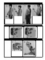
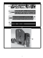
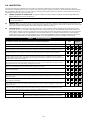
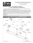
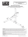
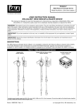
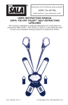
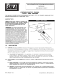
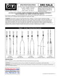
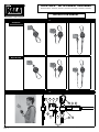
Rope-Safe™ with energy absorber
Model Numbers: 8700570, 8700571, 8700572, 8700620, 8700621, 8700643,
INSTRUCTION MANUAL
The Ultimate in Fall Protection
1
Industrial
8700570 0.3m (1 ft)
8700571
Rope Access
8700620 0.3m (1 ft)
8700643 0.6m (2 ft)
8700572
0.6m (2 ft)
0.9m (3 ft)
8700621 0.9m (3 ft)
2
A
B
C
D
H
I
K
L
J
E
F
G
Figure 1 – Form no: 5903793
Rev: A
© Copyright 2015, DB Industries, Inc.
3
4
H
G
A
B
B
C
D
I
C
5
F
A
B
C
D
A
E
F
E
J
6
A
B
C
D
E
F
2
G
7
C
B
A
D
8
B
A
9
A
B
3
10
A
B
11
A
B
12
A
J
K
E
ANSI & OSHA
Ø11 - 13mm
ASNZS & EN
Ø10.5 - 13mm
B
C
H
F
G
I
4
D
13
K
L
M
N
14
A
B
5
WARNING: This product is part of a personal fall arrest or restraint system. The user must follow the manufacturer’s instructions for
each component of the system. These instructions must be provided to the user of this equipment. The user must read and understand
these instructions before using this equipment. Manufacturer’s instructions must be followed for proper use and maintenance of this
equipment. Alterations or misuse of this product or failure to follow instructions may result in serious injury or death.
IMPORTANT: If you have questions on the use, care, or suitability of this equipment for your application, contact Capital Safety.
IMPORTANT: Before using this equipment, record the product identification information (see Figure 2) in Table 2 - Inspection and
Maintenance Log at the back of this manual.
1.0APPLICATIONS
PURPOSE: The Rope-Safe™ with Energy Absorber (Figure 1) is designed to be used as an automatic or manual rope grab
1.1
as part of a fall arrest and/or restraint system for a single user working at heights. The Rope-Safe with Energy Absorber
provides a portable connection point on a rope lifeline and includes an integral energy absorbing lanyard. The Rope-Safe
operates as a “follower” while in automatic mode. Manual mode allows the user to “park” the Rope-Safe in position on the lifeline
for work positioning or restraint. When “parked” the Rope-Safe can be moved up the lifeline towards the lifeline anchor but will
lock in position on the lifeline if pulled down the lifeline by hand or by the energy absorbing lanyard. Models 8700620, 8700621,
and 8700643 and can be towed in manual mode using the integral Tow Cord.
Figure 2 illustrates key components of the Rope-Safe with Energy Absorber:
A - UP Arrow Marking
D - Operation Switch
G - Swivel
J - Instruction Labels
B - Rope-Safe Housing
E - Cover Button
H - Carabiner
K - Shock Absorbing Lanyard
C - Cam Assist (Friction Cam)
F - Tow Cord (if equipped)
I - iSafe Product Label
L - Shock Pack (Energy Absorber)
1.2Standards: The Rope-Safe with Energy Absorber is approved for use under the following standards:
Standard
User Max Weight*
Application
Users
Standard
User Max Weight*
Application
Users
ANSI Z359.1
141kg (310lb)
Fall Arrest
1
EN 12841
141kg (310lb)
Fall Arrest
1
ANSI A10.32
141kg (310lb)
Fall Arrest
1
EN 12841
200kg (440lb)
Rescue
2
OSHA 1926.500
190kg (420lb)
Fall Arrest
1
AS/NZS 1891.3
160kg (353lb)
Fall Arrest
1
EN 353-2
141kg (310lb)
Fall Arrest
1
* Maximum combined weight of user(s), clothes, tools, etc.
1.3
REscue Plan: When using this equipment the employer must have a rescue plan and the means at hand to implement and
communicate that plan to users, authorized persons, and rescuers.
1.4Training: This equipment is intended to be used by persons trained in its correct application and use. It is the responsibility of
the user to assure they are familiar with these instructions and are trained in the correct care and use of this equipment. Users
must also be aware of the operating characteristics, application limits, and the consequences of improper use. Consideration
should be given to the user’s age, fitness and physical or mental limitations that could have a detrimental affect on the safe use of
this equipment.
important: Training must be conducted without exposing the trainee to a fall hazard or must be used with backup fall
protection. Training should be repeated on a periodic basis.
1.5
Inspection Frequency: See Section 5 of this manual for inspection frequency and procedures.
2.0 equipment Limitations & Requirements
Always consider the following limitations and requirements when installing or using this equipment.
2.1
Rope type: The Rope-Safe with Energy Absorber is designed for use with synthetic kernmantle ropes (nylon, polyester or
blends of both materials).
Certified Rope Lifelines:
Part Numbers for Rope Lengths
15m (50 ft)
30m (100 ft)
60m (200 ft)
Material Description
11mm Rope Lifeline
8705115
8705116
8705117
13mm Rope Lifeline
8705122
8705123
8705124
Kernmantle Rope with
polyester cover and
nylon core.
AS/NZS and EN: 10.5mm to 13mm (27/64 in. to 1/2 in.)
Contact Capital Safety for
other available rope lengths.
ANSI and OSHA: 11 to 13mm (7/16 in. to 1/2 in.)
warning: Use of incompatible rope (construction and/or size) mar result in serious injury or death when operating
the Rope-Safe. Contact Capital Safety for other approved lifeline constructions.
2.2
free fall: Personal fall arrest systems must be rigged to limit a free fall to 1.8m (6.0 feet) or less when using the Rope-Safe
with Energy Absorber. Restraint systems must be rigged so that vertical free fall is not possible.
2.3
FALL CLEARANCE: There must be sufficient clearance below the user to arrest a fall before the user strikes the ground or other
obstruction. The clearance required depends on several factors:
• Deployment distance
• Free fall distance
• Energy absorbing lanyard length
• Elevation of anchorage
• Movement of harness attachment element
• Worker height
• Lifeline elongation
It is the user’s responsibility to calculate clearance based upon location, regional legislation, standards and situation.
6
Figure 3 illustrates Fall Clearance Parameters.
A: Rope-Safe
Connector Length
0.3m (1 ft)
A: Rope-Safe
Connector Length
0.6m (2 ft)
A: Rope-Safe
Connector Length
0.9m (3 ft)
B: Lifeline
Lengtha
C: Fall
Distance
D: Lifeline
Elongationb
E: Safety
Factor
F: Required
Fall Clearance
10m (33 ft)
1.8m (6.0 ft)
1m (3.3 ft)
1m (3.3 ft)
3.8m (12.5 ft)
25m (82 ft)
1.8m (6.0 ft)
2.5m (8.2 ft)
1m (3.3 ft)
5.3m (17.4 ft)
50m (164 ft)
1.8m (6.0 ft)
5m (16.4 ft)
1m (3.3 ft)
7.8m (25.6 ft)
100m (330 ft)
1.8m (6.0 ft)
10m (33 ft)
1m (3.3 ft)
12.8m (42.0 ft)
B: Lifeline
Lengtha
C: Fall
Distance
D: Lifeline
Elongationb
E: Safety
Factor
F: Required
Fall Clearance
10m (33 ft)
3.6m (11.9 ft)
1m (3.3 ft)
1m (3.3 ft)
5.6m (18.5 ft)
25m (82 ft)
3.6m (11.9 ft)
2.5m (8.2 ft)
1m (3.3 ft)
7.1m (23.4 ft)
50m (164 ft)
3.6m (11.9 ft)
5m (16.4 ft)
1m (3.3 ft)
9.6m (31.6 ft)
100m (330 ft)
3.6m (11.9 ft)
10m (33 ft)
1m (3.3 ft)
14.6m (48.2 ft)
B: Lifeline
Lengtha
C: Fall
Distance
D: Lifeline
Elongationb
E: Safety
Factor
F: Required
Fall Clearance
10m (33 ft)
4.5m (15 ft)
1m (3.3 ft)
1m (3.3 ft)
6.5m (21.6 ft)
25m (82 ft)
4.5m (15 ft)
2.5m (8.2 ft)
1m (3.3 ft)
8.0m (26.5 ft)
50m (164 ft)
4.5m (15 ft)
5m (16.4 ft)
1m (3.3 ft)
10.5m (34.7 ft)
100m (330 ft)
4.5m (15 ft)
10m (33 ft)
1m (3.3 ft)
15.5m (51.3 ft)
G: Anchor Point
H: Rope Lifeline
I: Working Level
J: Nearest Obstruction
Example: If a user
with the 0.6m (2 ft)
Rope-Safe has a lifeline
length of 15m (49 ft)
above the Rope-Safe,
the user will have a
required fall clearance
of 7.1m (23.4 ft).
Required Clearance (F) = Fall Distance (C) + Lifeline Elongation (D) + Safety Factors (E)
a
Lifeline Length = Distance from Anchor Point to Fall Arrestor
b
Lifeline Stretch = 10% of Lifeline Length. Static Kernmantle rope will have a specific amount of stretch under the load
of a fall as specified by the rope manufacturer and the standards body which it is manufactured under. Always take
into consideration the stretch from the anchor point to the worker when calculating clearance.
2.4
SWING FALLS: Swing falls occur when the anchorage point is not directly above the point where a fall occurs. The force of striking
an object in a swing fall may cause serious injury. In a swing fall, the total vertical fall distance will be greater than if the user had
fallen directly below the anchorage point, thus increasing the fall clearance required to safely arrest the user. Minimize swing falls by
working as directly below the anchorage point as possible. Never permit a swing fall if injury could occur.
2.5HAZARDS: Use of this equipment in areas with surrounding hazards exist may require additional precautions to reduce the
possibility of injury to the user or damage to the equipment. Hazards may include, but are not limited to high heat, caustic
chemicals, corrosive environments, high voltage power lines, explosive or toxic gases, sharp edges, moving machinery, or
overhead materials that may fall and contact the user or fall arrest system. Avoid working where your lifeline may cross or
tangle with that of another worker. Avoid working where an object may fall and strike the lifeline, resulting in a loss of balance or
damage to the lifeline. Do not allow the lifeline to pass under arms or between legs.
Warning: When working with tools, materials, or in high temperature environments, ensure that associated fall protection
equipment can withstand high temperatures, or provide protection for those items.
2.6
COMPATIBILITY OF COMPONENTS: Capital Safety equipment is designed for use with Capital Safety approved components
and subsystems only. Substitutions or replacements made with non-approved components or subsystems may jeopardize
compatibility of equipment and may effect the safety and reliability of the complete system.
2.7
COMPATIBILITY OF CONNECTORS: Connectors are considered to be compatible with connecting elements when they have
been designed to work together in such a way that their sizes and shapes do not cause their gate mechanisms to inadvertently
open regardless of how they become oriented. Contact Capital Safety if you have any questions about compatibility.
Connectors (hooks, carabiners, and D-rings) must be capable of supporting at least 22.2 kN (5,000 lbs.). Connectors must be
compatible with the anchorage or other system components. Do not use equipment that is not compatible. Non-compatible
connectors may unintentionally disengage (see Figure 4). Connectors must be compatible in size, shape, and strength. Selflocking snap hooks and carabiners are required. Use only the supplied carabiner and energy absorber. Do not remove the energy
absorber or connector or add any other components in line.
Warning: Use only supplied carabiner and energy absorber. Do not remove the energy absorber or connector or add any
other components in line.
2.8
Making Connections: Use only connectors that are suitable to each application. Ensure all connections are compatible in
size, shape and hook strength. Do not use equipment that is not compatible. Ensure all connectors are fully closed and locked.
Capital Safety connectors (snap hooks and carabiners) are designed to be used only as specified in each product’s user’s
instructions. See Figure 5 for inappropriate connections. Capital Safety snap hooks and carabiners should not be connected:
A.
To a D-ring to which another connector is attached.
B.
In a manner that would result in a load on the gate.
Caution: Large throat snap hooks should not be connected to standard size D-rings or similar objects which will result
in a load on the gate if the hook or D-ring twists or rotates.
C.
In a false engagement, where features that protrude from the snap hook or carabiner catch on the anchor, and
without visual confirmation seems to be fully engaged to the anchor point.
7
D.
To each other.
E.
Directly to webbing or rope lanyard or tie-back (unless the manufacturer’s instructions for both the lanyard and
connector specifically allows such a connection).
F. To any object which is shaped or dimensioned such that the snap hook or carabiner will not close and lock, or that
roll-out could occur.
G.
In a manner that does not allow the connector to align properly while under load.
2.9
ANCHORAGE STRENGTH: Anchorages selected must have a strength capable of sustaining static loads applied in the
directions permitted by the system of at least:
ANSI
Application
Non-Certified Anchorage
Fall Arrest
22.2kN (5,000 lbs)
Two times the maximum arresting force
Certified Anchorage
Restraint
4.5kN (1,000 lbs)
Two times the foreseeable force for certified anchorages
Work Positioning
13.3kN (3,000 lbs)
Two times the foreseeable force for certified anchorages
Rescue
13.3kN (3,000 lbs)
Five times the foreseeable force for certified anchorages
AS/NZS
Anchorage
Fall Arrest, 1 user
15kN (3,400 lbs)
Restraint, 1 user
12kN (2,700 lbs)
Rescue, 2 users
21kN (3,400 lbs)
Certified Anchorage: An anchorage for fall arrest, positioning, or rescue systems that a qualified person certifies to be
capable of supporting the potential fall forces that could be incurred during a fall or that meet the criteria for certified anchorage
prescribed by the associated standard(s).
Multiple Systems: When more than system is attached to the anchorage, the strengths set forth shall be multiplied by the
number of systems attached to the anchorage.
From OSHA 1926.500 and 1910.66: Anchorages used for attachment of personal fall arrest systems shall be independent of any
anchorage being used to support or suspend platforms, and capable of supporting at least 5,000 lbs. per user attached, or be designed,
installed, and used as part of a complete personal fall arrest systems which maintains a safety factor of at least two, and is under the
supervision of a qualified person. In Canada, refer to local regulations where applicable.
IMPORTANT: Extreme working conditions (harsh environments, prolonged use, etc.) may require increasing the frequency
of inspections.
3.0installation and use
warning: Do not alter or intentionally misuse this equipment. Consult Capital Safety when using this equipment in
combination with components or subsystems other than those described in this manual. Some subsystem and component
combinations may interfere with the operation of this equipment. Use caution when using this equipment around moving
machinery, electrical hazards, chemical hazards, sharp edges, or overhead materials that may fall onto the lifeline. Failure to
heed this warning may result in equipment malfunction, serious injury, or death.
WARNING: Consult your doctor if there is reason to doubt your fitness to safely absorb the shock from a fall arrest. Age and
fitness seriously affect a worker’s ability to withstand falls. Pregnant women or minors must not use the fall arrester.
3.1Planning: Plan your fall protection or restraint system before starting your work. Account for all factors that may affect your
safety before, during, and after a fall. Consider all requirements and limitations defined in this manual.
3.2
Inspection before use: See Section 5 of this manual for inspection frequency and procedures.
3.3 Connect rope lifeline to anchorage. Select a rigid anchorage point that is capable of supporting the required loads.
See section 2.9 for list of required anchorage strengths per region. The anchorage location must be carefully selected to reduce
possible free fall and swing fall hazards and to avoid striking an object during a fall. For restraint systems the anchorage must
be located such that no vertical free fall is possible. The rope lifeline must meet requirements of section 2.1 and be free of
knots,cuts, burns, severely abraded areas and excessive wear. The rope lifeline must be protected from contact with sharp or
abrasive edges and surfaces.
3.4
CONNECT THE Rope-Safe with energy absorber to a rope lifeline: Never connect more than one personal fall
arrest or restraint system to a single lifeline.
The Rope-Safe uses a pivoting cover and locking internal cam to secure the Rope-Safe to the rope. (See Figure 6)
A. Switch the Rope-Safe to automatic mode. (See Section 3.6 for Automatic and Manual Mode instructions,)
B. Open the pivoting cover. Hold the Rope-Safe with the cover toward the user. Depress the cover button (grey button on rope
side of the Rope-Safe.
C. Swing the cover down to open.
D. Continue to swing the cover down until the friction cam is completely exposed.
E. Insert the rope lifeline between the friction cam and the Rope-Safe wall.
F. With the rope lifeline completely within the Rope-Safe, pivot the cover closed until the cover button re-engages the cover.
Never use a Rope-Safe with the cover in the open position or unlocked.
G. Confirm that the Rope-Safe locks on the rope by pulling down on the swivel connector. Always confirm that the Rope-Safe is
attached to the lifeline with the arrow pointing towards the anchor.
8
WARNING: Placing side loads on the Rope-Safe such as on a leading edge may result in damage to the unit, failure of the
Rope-Safe to operate properly or cause the Rope-Safe to unlock on the lifeline, any of which could cause injury or death.
3.5
CONNECT THE Rope-Safe with energy absorber to the user’s harness:
The Rope-Safe with Energy Absorber connects to the user’s harness with the energy absorbing lanyard and ANSI rated connector.
The locking gate on the connector is a triple action lock that requires the user to lift, turn and then open the gate’s barrel. The
gate automatically closes and locks. After allowing the gate to close, squeeze the gate of the carabiner to confirm that the lock
has engaged. Consult the harness manufacturer’s instructions regarding connections and safe operation. Except under rescue
conditions, never connect more than one person to a single Rope-Safe Fall Arrester. Harness connection point recommended for
Rope-Safe with Energy Absorber models (See Figure 7):
Rope-Safe Model
Length
Tow Cord
8700570
0.3M (1 ft)
No Tow Cord
8700620
0.3M (1 ft)
Tow Cord
8700571
0.6m (2 ft)
No Tow Cord
8700643
0.6m (2 ft)
Tow Cord
8700572
0.9m (3 ft)
No Tow Cord
8700621
0.9m (3 ft)
Tow Cord
Recommended Harness
Connection Point
Front D-Ring
Dorsal D-Ring
Mode of Operation
Shown in Figure 7
A
Automatic Mode
B
Manual Mode
C
Automatic Mode
D
Manual Mode
3. 6
Rope-Safe with Energy Absorber Use
Automatic and Manual Operation Modes: The Rope-Safe with Energy Absorber can be converted from automatic (follower) to
manual (towable) mode.
Automatic mode operation allows the Rope-Safe to be free to move on the rope lifeline. In automatic mode, the Rope-Safe will follow
the user while the user is ascending and lead the user when the user is descending. Movement on the lifeline is allowed because the
arresting cam is prevented from making direct contact with the lifeline (Figure 8 A). The cam will grip the lifeline (lock on the lifeline)
when the swivel connector engages the cam (in the event of a fall) and contact is made with the lifeline (Figure 8 B).
WARNING: Use of the Rope-Safe with Energy Absorber in automatic mode while working on porous or unstable granular surfaces,
such as sand or grains, is not recommended. In the event of surface instability, the user might sink slowly and not gain enough
momentum to cause the Rope-Safe to lock on the lifeline. The user could be enveloped, causing serious injury or death.
In manual mode operation, the Rope-Safe can be used for fall arrest and/or restraint. The Rope-Safe can move on the rope lifeline
in an upwards direction (toward the anchor) but remains locked when pulled downward (away from the anchor) by hand or by the
Energy Absorber.
Automatic and Manual Mode Selection.
Switch from Automatic to Manual Mode: (See Figure 9)
A. To switch from automatic mode to manual mode, depress the operation switch in the middle of the Rope-Safe.
(Figure 9 A) The cam assist will lock on the rope.
B. While in manual mode, pull down on the Rope-Safe with Energy Absorber to lock the Rope-Safe on the rope lifeline. (Figure 9
B)
Switch from Manual to Automatic Mode when the Rope-Safe is locked on the rope lifeline: (See Figure 10):
A. Reach into the top of the Rope-Safe with a single finger. (Figure 10 A)
B. Push the cam assist forward toward the rope lifeline until it clicks into place, engaging the operation switch.
(Figure 10 B) Once engaged, the cam assist will not contact the lifeline and the Rope-Safe can move freely on the lifeline.
3. 7Tow Cord Use (if equipped) in Manual Mode: (See Figure 11)
Some Rope-Safe with Energy Absorber models include a tow cord. The tow cord can be used for lowering the Rope-Safe during
manual operation. Gently pull on the tow cord to cause the Rope-Safe to begin to move lower on the lifeline. Figure 11 A shows
the Rope-Safe being towed. Figure 11 B shows the Rope-Safe being towed with a descent device.
If the user pulls too hard (as in a fall) the Rope-Safe will lock off and the tow cord will release at the breakaway fuse connection
to the Rope-Safe. The Rope-Safe will then lock on the rope lifeline to prevent the user from descending. If the tow cord releases,
the user can reconnect the tow cord by snapping the cylindrical connectors back together. Do no modify the tow cord in any way
and do not attempt to bypass the breakaway fuse connection.
Warning: Placing side loads on the Rope-Safe such as on a leading edge may result in damage to the unit, failure of the
Rope-Safe to operate properly or cause the Rope-Safe to unlock on the lifeline, any of which could cause injury or death.
3. 8
after a fall: Any equipment which has been subjected to the forces of arresting a fall or exhibits damage consistent with the
effect of fall arrest forces as described in Section 5 must be must be taken out of service immediately and destroyed to prevent
further use.
4.0Training
4.1
It is the responsibility of all users of the Rope-Safe with Energy Absorber to understand these instructions and to be trained in the
correct installation, use, and maintenance of the device. These users must be aware of the consequences of improper installation
or use of this equipment. This user manual is not a substitute for a comprehensive training program. Training must be provided on
a periodic basis to ensure proficiency of the users.
Important: Training must be conducted without exposing the trainee to a fall hazard or must be used with backup fall
protection. Training should be repeated on a periodic basis.
9
5.0Inspection
The Rope-Safe with Energy Absorber must be visually and manually inspected by the user before and after each use. It must be
inspected by a competent person every 6 months to verify that the device is operating correctly. If the Rope-Safe with Energy Absorber
fails an inspection, has been used in an actual rescue (not training) and/or has seen the force of a fall, it must be taken out of service
immediately and destroyed to prevent further use.
5.1
Unsafe or Defective conditions: If inspection reveals an unsafe or defective condition, remove the Rope-Safe with
Energy Absorber from service and destroy it.
IMPORTANT: The Rope-Safe with Energy Absorber is not repairable. Do not alter or attempt to repair the Rope-Safe
with Energy Absorber.
5.2
Product Life: The functional life of the Rope-Safe with Energy Absorber is affected by work conditions and maintenance. As
long as the product passes the inspection criteria described in Section 5 of this manual it may remain in service for a period of ten
years from the date of manufacture, after which it must be removed from service.
5.3i-safe rfid tag: The Rope-Safe with Energy Absorber ID Label includes an i-Safe™ Radio Frequency Identification (RFID)
tag (Figure 12, item K). The i-Safe™ RFID tag can be used in conjunction with the i-Safe handheld reading device and the web
based portal to simplify inspection and inventory control and provide records for fall protection equipment. If you are a first-time
user, contact a Customer Service representative in the US at 800-328-6146, in Australia at 1800 245 002 or in New Zealand
at 0800 212 505. If you have already registered, go to: http://www.capitalsafety.com/en-us/Pages/i-Safe.aspx. Follow the
instructions provided with the i-Safe handheld reader or on the web portal to transfer your data to the web log.
Table 1 – Inspection Checklist
See Figure 2 for Rope-Safe with Energy Absorber component identification.
User
Pass
Fail
Competent
Person
Pass
Fail
Confirm there are no cracks, corrosion or deformation to the housing or any other part of the Rope-Safe.
All labels and markings must be present and legible. Inspect markings and labels on all components of the
device including the device body and the label pack attached to the energy absorber. (See Figures 12 and 13.)
Confirm that the carabiner is not bent, rusted/corroded or deformed, the gate opens and automatically closes
and locks and that it is not gouged or nicked in a way that could damage the attached energy absorber.
Confirm there is no corrosion, debris or other substances which could hamper the operation of the Rope-Safe.
Closely examine the cam assist, cover button, operation switch and swivel to confirm that all are operating
smoothly. Where debris or other substances have accumulated and affect the operation of the Rope-Safe, clean
the Rope-Safe as described in Section 6.
Operate the cover, confirming that it opens and closes smoothly. Confirm that the cover locks into place and only
opens when the cover button is depressed. When closing the cover, invert the Rope-Safe and confirm that the
gravity latch stops the cover from closing. (See Figure 14, item A)
Open the cover and invert the Rope-Safe and confirm that the inertial cam flips down. Inspect the inertial cam to
confirm it is not damaged and that it rotates freely.(See figure 14, item B)
Attach the Rope-Safe to the rope lifeline and confirm that the Rope-Safe will lock on the lifeline when activated
by the swivel connector.
Depress the operation switch to confirm that it locks on the rope lifeline in manual mode.
If equipped with a tow cord: with the Rope-Safe in manual mode, operate the Rope-Safe by pulling it down the
rope lifeline using the tow cord. Switch the Rope-Safe back to automatic and confirm that it will follow the user
without restriction.
Confirm that there are no cuts, burns or damage to the lanyard material and that the energy absorber has not
been deployed or damaged.
After the rope lifeline is threaded into the Rope-Safe and prior to descending, put weight on the Rope-Safe to
confirm that it locks onto the rope. While in manual mode, pull on the tow cord (if equipped) to confirm that
descent can occur.
The device includes an integrated energy absorbing lanyard and ANSI rated connector. If any component of the system is missing or replaced
with a non-factory supplied component, the Rope-Safe with Energy Absorber must be removed from service.
Record inspection dates and results in Table 2 - Inspection and Maintenance Log.
Full Body Harness
Inspect the Full Body Harness according to the manufacturer’s instructions.
Rope Lifeline
Inspect the Rope for knots, cuts, burns,severely abraded areas and excessive
wear. Inspect the rope lifeline according to the manufacturers instructions.
10
6.0 Cleaning, Maintenance, and STORAGE
6.1
The Rope-Safe should be cleaned in clean lukewarm water and allowed to dry away from direct sunlight. Cleaning and drying
should be carried out immediately after every use in a marine environment. Keep the Energy Absorber dry.
Examine the Rope-Safe cam and cam assist to ensure any grit is removed and they are moving smoothly. A light cleaning agent
such as WD-40 or equivalent may be used to remove grit, dirt and grime that may cause stiffness in the operation of the cam.
When a cleaning agent is used, ensure that all remnants are washed off the Rope-Safe.
Store in a clean, dry environment. Avoid temperature extremes, corrosive fumes or chemical substances. If the Rope-Safe with
Energy Absorber comes into contact with chemicals refer to chemical data sheets and/or the manufacturer. When not in use or in
transport, the Rope-Safe with Energy Absorber should be properly protected from the elements and whenever possible kept in a
protective bag, dry and out of direct sunlight.
When the Rope-Safe with Energy Absorber is used in extremely cold weather, be aware if there is a possibility of water/ice coming
into contact with the moving parts of the Rope-Safe. Confirm that all Rope-Safe with Energy Absorber components are free of ice.
Rope lifelines should not be stored in direct sunlight or where they may be affected by any heat source. Storage area humidity should
be 60% and temperature should be approximately 75°F (24°C). Ropes should not come into contact with any chemicals and should be
removed from service if they come into contact with chemicals outside the PH range of 5.5 – 8.5.
6.2
Clean and store all other system components according to the manufacturers’ instructions.
7.0specifications
8.0markings and labels
Model
Length
Weight
Tow Cord
See Figure 12
8700570
0.3m (1 ft)
0.8kg (1.9 lb)
No
A
Manufacturer’s name/Mark.
G
User must read instructions.
8700571
0.6m (2 ft)
0.9kg (2.0 lb)
No
B
Part number/model.
H
Certifying agency.
8700572
0.9m (3 ft)
1.0kg (2.2 lb)
No
C
Date of manufacture MM/YY.
I
Maximum rated load.
D
Serial number.
J
Do not remove energy absorber.
Do not use without energy absorber.
E
Range of rope sizes and construction
suitable for the Rope-Safe.
K
i-safe RFID tag is imbedded in the
ID label.
F
Number and year of standard.
8700620
0.3m (1 ft)
0.8kg (1.9 lb)
Yes
8700643
0.6m (2 ft)
0.9kg (2.0 lb)
Yes
8700621
0.9m (3 ft)
1.0kg (2.2 lb)
Yes
See Figure 13
K
Read user instructions.
M
Warnings (French)
L
Warnings
N
Inspection Log / User Information.
Table 2 – Inspection and Maintenance Log
SERIAL NUMBER:
MODEL NUMBER:
DATE PURCHASED:
INSPECTION DATE
DATE OF FIRST USE:
INSPECTION ITEMS NOTED
CORRECTIVE ACTION
Approved By:
Approved By:
Approved By:
Approved By:
Approved By:
Approved By:
Approved By:
Approved By:
Approved By:
11
MAINTENANCE PERFORMED
LIMITED LIFETIME WARRANTY
Warranty to End User: CAPITAL SAFETY warrants to the original end user (“End User”) that its products are free from defects in materials and workmanship under normal
use and service. This warranty extends for the lifetime of the product from the date the product is purchased by the End User, in new and unused condition, from a CAPITAL
SAFETY authorised distributor. CAPITAL SAFETY’S entire liability to End User and End User’s exclusive remedy under this warranty is limited to the repair or replacement
in kind of any defective product within its lifetime (as CAPITAL SAFETY in its sole discretion determines and deems appropriate). No oral or written information or advice
given by CAPITAL SAFETY, its distributors, directors, officers, agents or employees shall create any different or additional warranties or in any way increase the scope of this
warranty. CAPITAL SAFETY will not accept liability for defects that are the result of product abuse, misuse, alteration or modification, or for defects that are due to a failure to
install, maintain, or use the product in accordance with the manufacturer’s instructions. THIS WARRANTY IS THE ONLY WARRANTY APPLICABLE TO OUR PRODUCTS AND IS IN
LIEU OF ALL OTHER WARRANTIES AND LIABILITIES, EXPRESSED OR IMPLIED.
LIMITED LIFETIME WARRANTY - AUSTRALIA
Warranty to End User: Capital Safety Group (Australia) Pty Ltd (“Capital Safety”) warrants to the original end user (“End User”) that its products are free from defects in
materials and workmanship under normal use and service. This warranty extends for the lifetime of the product from the date the product is purchased by the End User, in
new and unused condition, from a Capital Safety authorized distributor. This warranty is provided in addition to other rights and remedies available to the End User under law.
No oral or written information or advice given by Capital Safety, its distributors, directors, officers, agents or employees shall create any different or additional warranties or
in any way increase the scope of this warranty. This warranty will not apply to and Capital Safety will not accept liability for defects that result from product abuse, misuse,
alteration or modification, or for defects that are due to a failure to install, maintain or use the product according to the manufacturer’s instructions.
Capital Safety’s warranty applies only to the End User. To obtain the benefit of this warranty, the End User must register the purchased product at capitalsafety.com.au under
“Warranty Registration” tab, or retain their original receipt as proof of purchase.
To claim under this warranty, the End User should return the product with an explanation of the product issue, along with the original proof of purchase, to:
CAPITAL SAFETY AUSTRALIA
95 Derby Street, Silverwater, NSW 2128
Phone: 02 8753 7600/Toll free: 1800 245 002
Email: [email protected]
The End User must pay the cost of packaging and returning the product to Capital Safety.
Limitation of Warranty: The warranties stated in this document are exclusive and are made in place of any and all conditions, warranties or representations as to the
merchantability, performance, quality or fitness for a particular purpose of the product that may be implied by law, and in place of any industry practice or custom or trade
usage.
The product comes with guarantees that cannot be excluded under Australian Consumer Law. The End User is entitled to a replacement or refund for a major failure and
to compensation for any other reasonably foreseeable loss or damage. The End User is also entitled to have the product repaired or replaced if the product fails to be of
acceptable quality and the failure does not amount to a major failure.
Limitation of Liability: To the extent permitted by law:
(a) Capital Safety’s maximum liability to the End User for failure to comply with a consumer guarantee in respect of the supply of the product not of a kind ordinarily acquired
for personal, domestic or household use or consumption is limited, at Capital Safety’s sole discretion, to repair or replacement of the product; and
(b) Capital Safety will not be liable for any direct, indirect, special, or consequential damages of any kind, including loss of profits, revenue or business, death, personal
injury or damage to property resulting from or in any way related to Capital Safety’s products.
Australia & New Zealand
95 Derby Street
Silverwater
Sydney NSW 2128
Australia
Phone: +(61) 2 8753 7600
Toll-Free : 1800 245 002 (AUS)
Toll-Free : 0800 212 505 (NZ)
Brazil
EMEA (Europe, Middle East, Africa) Fax: +(61) 2 8753 7603
Rua Anne Frank, 2621
EMEA Headquarters:
[email protected]
Boqueirão Curitiba PR
5a Merse Road
Asia
81650-020
North Moons Moat
Singapore:
Brazil
Redditch, Worcestershire
69, Ubi Road 1, #05-20
Phone: 0800-942-2300
B98 9HL UK
[email protected]
Phone: + 44 (0)1527 548 000
Oxley Bizhub
Singapore 408731
Fax: + 44 (0)1527 591 000
Mexico
Phone: +65 - 65587758
[email protected]
Calle Norte 35, 895-E
Fax: +65 - 65587058
Col. Industrial Vallejo
[email protected]
France:
C.P. 02300 Azcapotzalco
Le Broc Center
Mexico D.F.
Shanghai:
Z.I. 1re Avenue - BP15
Phone: (55) 57194820
06511 Carros Le Broc Cedex
Rm 1406, China Venturetech Plaza
[email protected]
819 Nan Jing Xi Rd,
France
Shanghai 200041, P R China
Phone: + 33 04 97 10 00 10
Colombia
Phone: +86 21 62539050
Compañía Latinoamericana de Seguridad S.A.S. Fax: + 33 04 93 08 79 70
Fax: +86 21 62539060
Carrera 106 #15-25 Interior 105 Manzana 15 [email protected]
[email protected]
Zona Franca - Bogotá, Colombia
USA
3833 SALA Way
Red Wing, MN 55066-5005
Toll Free: 800.328.6146
Phone: 651.388.8282
Fax: 651.388.5065
[email protected]
Canada
260 Export Boulevard
Mississauga, ON L5S 1Y9
Phone: 905.795.9333
Toll-Free: 800.387.7484
Fax: 888.387.7484
[email protected]
Phone: 57 1 6014777
[email protected]
www.capitalsafety.com
I S O
9001