1
ALBERTA INFRASTRUCTURE
GUIDELINE
FOR
HIGH PERFORMANCE MODULAR CLASSROOM CONTROLS
2013
Capital Projects
Technical Services Branch
Alberta Infrastructure Guideline for High Performance Modular Classroom Controls
Table of Contents
1.
GENERAL ......................................................................................................................... 2
1.1
1.2
1.3
2.
GENERAL
BUILDING OPERATING MODES
DEFINITIONS, SETUP PARAMETRS AND SYSTEM VARIABLES
BASIC DATA GATHERING
DETERMINATION OF OCCUPANCY
PACKAGED HVAC UNIT CONTROL - DETAILS
LIGHTING CONTROL
EMERGENCY CONTROL
CO2 MONITORING AND CONTROL
ALARM PROGRAMS
6
9
10
13
14
16
20
21
22
23
CONTROLS O&M MANUAL, O&M DISK AND SYSTEM BACKUP
TEACHER’S GUIDE
EMERGENCY PROCEDURES SHEET
24
26
27
CONTROLLER HARDWARE AND SOFTWARE ................................................... 27
5.1
5.2
6.
3
4
4
DOCUMENTATION...................................................................................................... 24
4.1
4.2
4.3
5.
GENERAL
BASIC OPERATIONAL OBJECTS:
ENGINEERING / MAINTENANCE RELATED OBJECTS:
CONTROL SEQUENCES ............................................................................................... 6
3.1
3.2
3.3
3.4
3.5
3.6
3.7
3.8
3.9
3.10
4.
2
2
2
STANDARD FUNCTIONAL PROFILE ........................................................................ 3
2.1
2.2
2.3
3.
INTENT
ABBREVIATIONS
BASIC MECHANICAL & ELECTRICAL REQUIREMENTS
PROGRAMMABLE CONTROL UNIT (PCU) & INTELLIGENT THERMOSTAT
PROGRAMMING/CONFIGURATION TOOL AND MANUALS
27
28
EXECUTION .................................................................................................................. 30
6.1
6.2
6.3
6.4
6.5
6.6
6.7
OCCUPANCY AND LIGHT SENSORS / DEVICES
WIRING AND INSTALLATION
IDENTIFICATION
GROUNDING
SCHOOL INTERFACE CABINET AND TERMINAL STRIP
TRAINING OF OPERATORS
MISCELLANEOUS
30
30
31
32
32
33
33
1
Alberta Infrastructure Guideline for High Performance Modular Classroom Controls
1.
General
1.1
INTENT
.1
The intent of this document is to provide guidance regarding the scope, installation,
configuration and programming of the system that will be used to control the
mechanical equipment and lighting in a high performance modular classroom. It will
also cover backups and documentation for operations staff as well as a user guide for
teaching staff.
.2
A major aim of the AI High performance modular classroom Program is to provide
students and teachers with classroom units that have a level of indoor air quality and
comfort comparable to that of any regular classroom. AI has also embraced the
concept of Green design and the high performance modular classrooms are being
designed and constructed with these initiatives in mind. The guideline will deal with
the desired control sequences to be used to provide this comfortable environment in
an energy efficient manner. These will integrate mechanical system control,
occupancy sensing, equipment scheduling as well as lighting override/control.
.3
Additional operational features such as tie-ins for a school security system and dialout mechanical alarm will also be detailed.
.4
A major component of the guideline is to provide a common interface “profile”
based upon BACnet objects to facilitate interfacing various classrooms from
differing vendors into a school’s EMCS network in a standardized fashion.
1.2
ABBREVIATIONS
.1
.2
.3
.4
.5
.6
1.3
BACnet:
Protocol
CCS:
EMCS:
PCS
PCU:
PID:
ASHRAE Standard Building Automation & Control Network
Central Control Station
Energy Management Control Systems
Portable Control Station
Programmable Control Unit
Proportional Integral Derivative
BASIC MECHANICAL & ELECTRICAL REQUIREMENTS
.1
The mechanical system is to include:
.1
an exhaust fan to ensure positive entry of 212 L/s of fresh air
.2
heating with minimum 4-1 turndown, 2-1 if heat reclaim is provided
.3
humidifier
.4
small sump and sump pump, c/w high level alarm
.5
100% outside air free cooling capability
2
Alberta Infrastructure Guideline for High Performance Modular Classroom Controls
.6
.7
mixing dampers for non-displacement systems
heat reclaim and CO2 sensor
.2
System must be designed and component sizing selected such that temperature swing
during any form of cycling operation under any heating, cooling or ventilation mode
is less than 5 degC.
.3
Include room for DX cooling and all necessary controls and programming for this
function whether or not classroom is being equipped with cooling.
.4
System must be designed such that there are no marked changes in classroom
pressurization under any combination of supply fan speed, damper position or
exhaust fan operating status.
.5
A contactor is required for overall control of the lighting. If daylight harvesting is
being employed, then additional controls or control interfaces will be required.
Ensure these are compatible with the PCU.
.6
Program start ballasts are required to preserve lamp life under frequent switching.
.7
Mechanical and electrical requirements must be coordinated with the mechanical and
electrical disciplines.
2.
Standard Functional Profile
2.1
GENERAL
.1
The ultimate purpose of a high performance modular classroom is to allow it to be
moved from one site to another with little difficulty. Since it is expected that
classrooms will be sourced from a variety of manufacturers and will be supplied with
different mechanical systems, it is necessary to ensure that the controls appear the
same from one classroom to another, in as much as this is possible. Without such
standardization, significant unnecessary expense is added to a move.
.2
BACnet has been chosen as the interface standard mainly because all previous high
performance modular classrooms have included native BACnet compliant hardware.
However, a major benefit of BACnet is that it allows auto-discovery of connected
hardware and exposed “objects”. Integration of a high performance modular
classroom to a school’s EMCS is greatly facilitated if the exposed objects follow a
common naming convention and offer identical functionality. Consistency of
common features is mandatory.
.3
For the purposes of this guideline, these objects will be broken down into three types:
3
Alberta Infrastructure Guideline for High Performance Modular Classroom Controls
.1
.2
.3
.4
2.2
Basic operational objects required for day to day operation/interaction with
the mechanical system. These are not specific to actual equipment, but are
generic in nature. These include scheduling, occupancy, setpoints, failure
alarms etc.
Engineering objects required to setup features or tune the generic control
sequences. These include system status, setpoint offsets, control loop
parameters etc.
Product specific objects/options not included above.
In the following profile descriptions, the ## refers to the classroom number. It is
expected this portion of the name will need to be changed every time a classroom is
relocated and incorporated into a new network. Italicized names refer to variables or
virtual points.
BASIC OPERATIONAL OBJECTS:
Note: R=read, W=write, T=trend, O=override, C=Calibrate, A=alarm&limits
* = Objects that are required only if related options have been included
2.3
Name
Description and (units)
Interaction
RC##OAT
RC##ST
RC##RH
RC##CO2
RC##LL
RC##L
Outside Air Temperature AI (degC)
Space (classroom) Temperature AI (degC)
Space Relative Humidity AI (%RH)
CO2 AI (PPM)
Light Level AI (Lux)
Lighting Contactor DO (On/Off)
RTC
RTCA
RTCA
*RTC
*RT
RWTO
RC##OCCUPIED
RC##ST_USP
RC##LL_SP
RC##ST_24max
RC##ST_24min
RC##OAT_24max
RC##OAT_24min
RC##ST_24max
RC##ST_24min
RC##RH_24max
RC##RH_24min
RC##CO2_24max
RC##CO2_24min
Occupied Mode flag (Yes/No)
User Space Temp Setpoint (degC)
Light Level Setpoint (Lux)
Max space temp over last 24 hrs (degC)
Min space temp over last 24 hrs (degC)
Max OAT over last 24 hrs (degC)
Min OAT over last 24 hrs (degC)
Max space temp over last 24 hrs (degC)
Min space temp over last 24 hrs (degC)
Max RH value over last 24 hrs (%RH)
Min RH value over last 24 hrs (%RH)
Max CO2 value over last 24 hrs (PPM)
Min CO2 value over last 24 hrs (PPM)
RWTO
RWTO
*RWTO
RT
RT
RT
RT
RT
RT
RT
RT
*R
*R
ENGINEERING / MAINTENANCE RELATED OBJECTS:
4
Alberta Infrastructure Guideline for High Performance Modular Classroom Controls
Note: R=read, W=write, T=trend, O=override, C=Calibrate, A=alarm&limits
* = Objects that are required only if related options have been included
Name
Description and (units)
RC##SAT
RC##MAT
RC##OCCS
RC##TC
RC##OCCMOR
RC##FAULT
RC##SUMP_HI
Supply Air Temperature AI (degC)
RTCA
Mixed Air Temperature AI (degC)
RTCA
Occupancy Sensor DI (On/Off)
RT
Time Clock DI (Occupied/Unoccupied)
RT
Man Occup Override Button DI (On/Off) RWO
Mech fault DI, flamefail etc (Alarm/Normal) RTA
High Sump level Alarm DI (Alarm/Normal) RTA
RC##SF
RC##EF
RC##H
RC##HTG_E
RC##CLG
RC##CLG_E
RC##MALM
RC##MAD
RC##HTG_R
Supply Fan continuous run DO (On/Off)
Exhaust Fan DO (On/Off)
Humidifier control DO (On/Off)
Heating Enable DO (enabled/disabled)
Cooling element (DX coil) DO (On/Off)
Cooling Enable DO (Enabled/Disabled)
Mechanical Alarm DO (Alarm/Normal)
Mixed Air Damper AO (%)
Heating Reset AO (%)
RC##OCCsched
Occupancy Schedule Option (Yes/No)
RC##OCCtclk
Occupancy TimeClock Option (Yes/No)
RC##OCCesave
Occupancy EnergySave Option (Yes/No)
RC##OCCco2
CO2 Control Option (Yes/No)
RC##CLG_INSTALLED Cooling Available option (Yes/No)
RC##OCC_MORT Occupancy Manual Override Time (min)
RC##OCC_TMR
Manual occupancy count down timer (min)
RC##OCC_WS
Occupied Mode Weekly Schedule
All schedule setup parameters
Interaction
RWTO
RWTO
RWTO
*RWTO
RWTO
*RWTO
RTA
RWTO
*RWTO
RWO
RWO
RWO
RWO
RWO
RWO
R
RWTO
RW
5
Alberta Infrastructure Guideline for High Performance Modular Classroom Controls
RC##OCC_AS
Occupied Mode Annual Schedule
All schedule setup parameters
RC##OCC_PROB Occupancy Probability (%)
RC##ST_SP
Operating Space Temp Setpoint (degC)
RC##ST_SPmax
Max allowed SpaceTemp setpt (degC)
RC##ST_SPmin
Min allowed SpaceTemp setpt (degC)
RC##ST_NSP
Night setback space temp setpoint (degC)
RC##ST_CO
Space Temp Controller Output Value (%)
All control loop setup parameters
RC##ST_PG
ST Loop Proportional Gain ( )
RC##ST_IG
ST Loop Integral Gain ( )
RC##RH_SP
RH Setpoint (%)
RC##SAT_SP
SAT Setpoint (degC)
RC##MAT_SP
MAT Setpoint (degC)
RC##MAT_CO
Mix Air Temp Controller Output Value (%)
All control loop setup parameters
RC##MAT_PG
MAT Loop Proportional Gain ( )
RC##MAT_IG
MAT Loop Integral Gain ( )
RC##MAD_MIN
Mixed Air Damper Min Posn. (%)
RC##HTG
Heating element output value (%)
Note: multi stage firing value would also
be shown in % of fire i.e. 50%, 100%
RC##HR_DFRST Heat Reclaim in Defrost mode (Yes/No)
RC##HR_DFRSTdur Defrost cycle duration (minutes)
RC##HR_DFRSTper Defrost cycle period (hours)
RC##L_INTMR
Lighting Interupt Timer (On/Off)
RC##CO2_SP
CO2 Setpoint (PPM)
RC##CO2_HIALM CO2 High Alarm (Alarm/Normal)
RC##CO2_FAULT CO2 sensor fault (Alarm/Normal)
RC##DTIME
Decimal 24hr Time (Hrs)
3.
Control Sequences
3.1
GENERAL
.1
RWTO
RW
RWTO
RWTOA
RW
RW
RWTO
RWTO
RW
RWO
RWO
RWTO
RWTO
RWTO
RWTO
RW
RWO
RWO
RWTO
RT
*RWTO
*RWTO
*RWTO
RWTO
*RWTO
*RTA
*RWTOA
RT
In many ways, the older standalone portables were somewhat less problematic
because these mechanical systems were very simple in nature and the typical
thermostat interface was generally straight forward in nature and well understood by
most people. Unfortunately, the older mechanical systems did not provide good
comfort conditions, were not energy efficient and could not be counted-on to provide
the required amount of outside air for proper ventilation.
6
Alberta Infrastructure Guideline for High Performance Modular Classroom Controls
.2
In response to indoor air quality concerns and energy efficiency, the current high
performance modular classrooms have mechanical and control systems that are much
more complex. Heating is now modulated or at least staged, mixing dampers
modulate in response to space demands, mechanical cooling may be available and
heat reclaim is now standard. Occupancy can be scheduled or sensed and lighting
controls can be simple overrides or include daylight harvesting. Resulting control
sequences are not only lengthy but more highly integrated.
.3
Programming style should be of a form that enables the control strategies to be easily
followed. Clarity, simplicity and elegance are more important than program size.
Extensive inclusion of comments is mandatory. Hundreds of classrooms will be
constructed, a little extra time spent in preparation and documentation will have huge
paybacks during warrantee and beyond.
.4
Text based programs must be modular in nature and as structured as the language
will permit. Unconditional branching should be used sparingly. All jumps from the
body of a module should target the end of that module. Similarly, jumps from the
body of a sub-module should target the end of that sub-module.
.5
Graphic style programming must be nested/broken into easily manageable modules
that can be clearly shown on letter sized sheets. Each to be well annotated with text
descriptions of the function of each such graphic page. Large function blocks should
have all parameters listed on accompanying pages.
.6
The control sequences need to accommodate the following scenarios:
.1
Controls completely self contained with occupancy determined by classroom
occupancy sensor only. When occupancy is sensed, lights are enabled and the
mechanical system operates in daytime occupied mode. When occupancy is
no longer being sensed, the outside air is slowly decreased to zero, after a
time delay, lights are turned off and the mechanical system is shut down and
operated in night setback mode.
.2
Controls completely self contained with occupancy determined by internal
weekly and annual schedules. Mechanical systems and lights operate during
occupied hours regardless of occupancy sensor readings. During unoccupied
hours, the occupancy sensor only enables lighting, the mechanical system
remains in night setback mode.
.3
Controls completely self contained, similar to 2) above, but occupancy sensor
is also used in occupied mode to save extra energy by decreasing outside air
intake and turning out the lights when no occupancy is sensed. This is the
default mode of operation.
.4
Controls interfaced to simple time-clock. Similar to 2) above, but external
contact input is used instead of internal schedules.
7
Alberta Infrastructure Guideline for High Performance Modular Classroom Controls
.5
Controls interfaced to simple time-clock similar to 4) above, but occupancy
sensor is used in occupied mode to save extra energy by decreasing outside
air intake and turning out the lights when no occupancy is sensed.
.6
Controls interfaced to school EMCS. Similar to 4) or 5) above but school’s
EMCS can be programmed to override classroom’s internal occupancy
schedules, energy savings option flag as well as the various setpoints. If
necessary, it would also be possible to perform these as well as other
functions manually from offsite.
.7
Manual activation of override timer forces mechanical system into normal
occupied operating mode for a predetermined interval, irrespective of any of
the above settings.
.7
The mechanical system may use a modulating or multistage gas valve or even some
other form of heating. The system will also use some form of heat recovery. This
may be in the form of a heat wheel, heat pipe or air-to-air heat exchanger with built
in exhaust fan. The programming must be written such that these differences are
hidden from the basic operational profile. As an example, heating is to be a value
between 0-100%. This can directly represent a modulating gas valve or electric
heating coil. Multistage firing rates would show as stepped values (i.e. 4 stages
would be 25%, 50%, 75%, 100%). Special, vender specific, setup parameters could
be made available via additional product specific objects/options.
.8
Although mechanical cooling may not be installed when a high performance modular
classroom is constructed, many boards add cooling soon after delivery. Direct DX
cooling control point RC##CLG and/or cooling system enable point RC##CLG_E
must be provided as well as all related control strategies. Parameter
RC##CLG_INSTALLED units "Yes/No" is used to enable/disable control of
cooling.
.9
It is not necessary to create programming exactly as shown in the following articles.
The sample programming uses various techniques and mixed mode mathematics that
are not available to all systems. Such details should be treated as a guideline as to
how the sequences are to operate. It is not the intent of this guideline to limit the
vendor to specific methods of programming or diminish their responsibility for
producing a reliable product. More efficient strategies and techniques are welcome
as long as the functionality described in this guideline is incorporated and comfort
and energy efficiency are not compromised.
8
Alberta Infrastructure Guideline for High Performance Modular Classroom Controls
.10
3.2
Controls programming MUST take into account the possibility of improper user
input. Humans are fallible and make entry and judgment errors. Setpoints and other
input should be checked for reasonableness etc. There should be no way the unit
could be placed into an operating mode that would lead to premature equipment
failure, no matter how long the unit operates under these conditions. Error messages
should help guide the user to the correct action without implying a negative context.
For example, it would be better to say “Occupied setpoint must be within comfort
range 21 to 24 degC” rather than simply “Illegal entry” without any indication of
what was entered or what is the allowed range.
BUILDING OPERATING MODES
.1
Three fundamental modes of operation are defined:
.1
Occupied: Normal operation, space at normal occupied setpoint, main fan
continuous operation, exhaust fan and mixing dampers set to provide required
outside air with free cooling capability and heating/cooling are enabled.
Pressing the thermostat’s occupancy button will put the space into occupied
mode operation for the number of minutes contained in variable
RC##OCC_MORT. The transition into occupied mode is also to incorporate
warm-up and purge functions as follows:
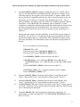
.1
Warm-up: This function is active whenever the space temperature is
noticeably below setpoint as would occur during startup after a night
setback period or with an equipment failure. During this mode, the
amount of fresh air is smoothly decreased to allow for greater heating
capacity and quicker recovery as follows:
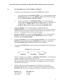
Temp. below setpt
3 degC
0.5 degC
programming
Max allowed mixing damper position
0 % (fully closed)
100% or as desired by normal
Mixing damper position
Less than ½ of RC##MAD_MIN
Greater or equal to RC##MAD_MIN
.2
Exhaust Fan
OFF
ON
Purge: This function simply disables mechanical DX cooling during
the first 20 minutes of occupancy.
9
Alberta Infrastructure Guideline for High Performance Modular Classroom Controls
3.3
.2
Occupied with Energy Savings Active: This is similar to the regular occupied
mode but includes features to conserve energy if no actual occupancy is being
sensed. As the probability of occupancy drops below 20%, the lights are
pulsed off for one second, mixing dampers slowly close over 5 minutes and
the exhaust fan goes off once the dampers have closed to less than ½ of their
minimum ventilation position. The one second lighting interruption notifies
any occupants that there has been insufficient activity to indicate occupancy
and all that is required is a single activation of the occupancy sensor to
reinstate normal occupied mode control.
.3
Unoccupied: Space at night setback temperature, supply fan off except as
required to intermittently heat the space, exhaust fan off and dampers fully
closed to outside air. This mode is entered directly if an external time-clock
or network override indicates that occupancy has ended. However, if
occupancy is being determined using the sensors, then the stepped response
used with the energy savings option precedes final system shutdown.
DEFINITIONS, SETUP PARAMETRS AND SYSTEM VARIABLES
.1
In the following control sequence descriptions, PHYSICAL POINTS are shown in
bold and capitalized and VIRTUAL POINTS are shown in bold and capitalized
italics.
.2
All parameters listed below must be able to be setup via an attached portable
computer or network connection to a central control station or, directly at the keypad
of the smart thermostat keypad.
NOTE: Keypad access to these settings must be protected with a pass code or similar
means.
.3
Parameter RC##CLG_INSTALLED: Cooling installed, units “Yes/No”, default
value “No”. Set this parameter to “Yes” if DX Cooling has been installed and is
available.
.4
Parameter RC##MAD_MIN: Minimum mixed air damper position, units “%”,
default value as required to ensure about 212 L/s of outside air will be provided
while the exhaust fan is running (i.e. typically somewhere between 30% and 40%).
.5
Parameter RC##OCCschd: Internal schedule option, units “Yes/No”, default value
“Yes”. Occupancy is determined via the internal weekly schedule RC##OCC_WS
and annual schedule RC##OCC_AS. If set to “No” then occupancy is assumed to be
determined via the occupancy sensors. Initially set up weekly scheduled occupied
hours between 7:30AM and 6:00PM, Monday through Friday. Set up annual holiday
schedule for the major holidays and summer vacation from mid July through to mid
August. School operator/custodian will need to make final adjustments on receipt of
classroom.
10
Alberta Infrastructure Guideline for High Performance Modular Classroom Controls
NOTE: If connected to school’s EMCS set the schedule option to yes and download
schedules from EMCS. As an alternative, set this option to yes and create a program
in the EMCS to override the status of the internal weekly and annual schedule based
upon the status of he EMCS’s schedules.
.6
Parameter RC##OCCtclk: Hardwired time clock option, units “Yes/No”, default
value “No”. Set parameter to “Yes” to indicate that occupancy is to be determined
via the external time clock input RC##TC. This takes precedence over the internal
weekly and annual schedules. Ideally, setting RC##OCCtclk to “Yes” would
automatically reset RC##OCCschd to “No”. As an alternative, it should not be
possible to set RC##OCCtclk to “Yes” if RC##OCCschd is already “Yes”.
.7
Parameter RC##OCCesave: Energy savings option, units “Yes/No”, default value
“Yes”. When enabled, the occupancy sensor is used to save extra energy when no
occupancy is sensed during occupied conditions by turning out the lights as well as
decreasing outside air intake during cold or extremely hot weather.
NOTE: This option makes no difference in manual occupancy override mode. It is
assumed someone wants everything up an running, no matter what the actual
occupancy.
.8
Parameter RC##OCCco2: CO2 control option, units “Yes/No”, default value “No”.
If available, the CO2 sensor is used to save extra energy by decreasing outside air
quantities requirements during occupied conditions during cold or extremely hot
weather.
.9
Variable RC##OCC_MORT: Occupancy Manual Override Time, units “Minutes”,
default value 60, entry limited to values between 30 and 240. This is the duration
that the system will be put into occupied mode whenever the intelligent thermostat’s
occupancy manual override button RC##OCCMOR is momentarily depressed.
.10
Variable RC##OCC_TMR: Manual Occupancy Count Down Timer, units
“Minutes”, default value 0. This timer indicates the number of minutes remaining in
occupied mode since the momentary closing of the intelligent thermostat’s
occupancy manual override button. The timer automatically counts down to zero and
is set to the manual override time value RC##OCC_MORT whenever button
RC##OCCMOR is depressed.
11
Alberta Infrastructure Guideline for High Performance Modular Classroom Controls
.11
Variable RC##OCC_PROB: Occupancy Probability, units of %, default value 0.
This is a value that indicates the likelihood that the classroom is occupied. In the
following sequence, the occupancy sensor must produce 3 captures within a short
time to provide 99% probability and since the value is always being decreased, one
activation every 6.6 minutes is required to keep probability above zero. This so
called probability of occupancy goes from 100 to zero if nothing has been sensed in
20 minutes. As an added feature, the probability value is limited to 33 when
schedules are enabled but indicating unoccupied OR a hardwired time clock is being
used but is also indicating an unoccupied period. This allows for a much faster
timeout should someone just pop in for a few moments to pick something up, or
whatever.
During manual occupancy override, probability is not valid because all systems are
forced ON. Just set value to 33% while in manual mode so probability is already
limited when counter times out. Should there still be significant occupancy in the
space, the probability will climb and the systems will remain in occupied mode as
desired.
Every 3 seconds do all of the following:
If RC##OCCS is “ON”
Then increase the value of RC##OCC_PROB by 33
Else decrease the value of RC##OCC_PROB by 0.25
Limit RC##OCC_PROB to values between 0 and 100%
If RC##OCCtclk is “Yes” AND input RC##TC shows unoccupied
OR RC##OCCschd is “Yes” AND schedules are showing an unoccupied
state
Then limit RC##OCC_PROB to values between 0 and 33%
If RC##OCC_TMR > 0 (i.e. occupancy manual override is active)
Then set RC##OCC_PROB to 33%
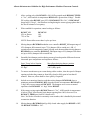
.12
Parameter RC##ST_SPmax: Maximum allowed Space Temp SetPoint, units
“DegC”, default value of 25.0, entry limited to values between 23 and 32.
.13
Parameter RC##ST_SPmin: Minimum allowed Space Temp SetPoint, units
“DegC”, default value of 21.0, entry limited to values between 17 and 22.
Variable RC##ST_USP: Space Temp User SetPoint, units “DegC”, default value of
22.5 DegC. This is the value of space temperature setpoint entered or adjusted by the
user via the intelligent stat keypad.
.14
.15
Controller RC##ST_CO: Space temperature control loop, output units “%”
Output Range: 0-100%, but limited to 0-75% if RC##CLG_INSTALLED is “No”
Bias: Set at 45%
12
Alberta Infrastructure Guideline for High Performance Modular Classroom Controls
Controlled variable: Space temperature RC##ST
Setpoint: RC##ST_SP
Parameter RC##ST_PG: Proportional gain, default value equivalent to 25%/degC
error
Parameter RC##ST_IG: Integral gain, default value equivalent to 5%/degC
error/hour
Miscellaneous: integral windup to be limited
.16
Controller RC##MAT_CO: Mixed air temp. control loop, output units “%”
Output Range: 0-100% (0% is for dampers at full return air)
Bias: Set at 0%
Controlled variable: Space temperature RC##MAT
Setpoint: RC##MAT_SP
Parameter RC##MAT_PG: Proportional gain, default value equiv to 25%/degC error
Parameter RC##MAT_IG: Integral gain, default value equivalent to 5%/degC
error/hour
Miscellaneous: integral windup to be limited
.17
Parameter RC##HR_DFRSTdur: Heat reclaim defrost cycle duration, units
“Minutes”, default value of 10 minutes.
.18
Parameter RC##HR_DFRSTper: Heat Reclaim defrost cycle period, units “Hours”,
default value of 8 hours.
.19
Variable RC##HR_DFRST: Heat reclaim in defrost mode, units “Yes/No”, default
value of “No”.
.20
Interrupt timer RC##L_INTMR: Lighting Interrupt Timer, units “On/Off”, default
value is Off. This timer is to turn “On” for one second every time probability
RC##OCC_PROB drops below 20%. It resets after the one second activation and
waits until the probability value once again goes above 20% then activates again
whenever the probability value passes down through 20%.
.21
Variable RC##DTIME: Decimal Time, units “Hours”. This is the value of PCU
time in decimal hours in 24 hour format. It can be used to check PCU clock
synchronization, communications issues etc.
BASIC DATA GATHERING
.1
Create routines that provide the following maximum and minimum values over a
sliding window period of the last 24 hours (hourly data is sufficient):
3.4
.1
.2
.3
.4
.5
RC##OAT_24max: Maximum outside air temperature
RC##OAT_24min: Minimum outside air temperature
RC##ST_24max: Maximum classroom space temperature
RC##ST_24min: Minimum classroom space temperature
RC##RH_24max: Maximum classroom relative humidity
13
Alberta Infrastructure Guideline for High Performance Modular Classroom Controls
.6
.7
.8
3.5
RC##RH_24min: Minimum classroom relative humidity
RC##CO2_24max: Maximum classroom CO2 level
RC##CO2_24min: Minimum classroom CO2 level
DETERMINATION OF OCCUPANCY
.1
Occupancy sensors are to be dual technology (IR/UV, IR/Ultrasonic, etc). Select
devices specifically designed for this application. The output contact should turn ON
when either one of the sensor technologies is activated, but should turn OFF only
when both technologies are indicating off (not just one of the two).
.2
Determination of occupancy is simple when time schedules or a time clock are
available. However, in self contained mode or whenever the energy savings option is
active, occupancy can only be determined via motion sensors mounted near the
windows and sensing into the room.
.3
In practice it has been difficult to find a balance between responsiveness and
nuisance activations. One wishes to avoid going into fully occupied mode should
someone just look into the room, but it should not require there to be 10 people
moving about the room either. The first indication of occupancy must enable the
lights, but more activations should be required to bring on the mechanical systems.
.4
The strategy should cover the possibility of a couple of students working quietly and
also provide a somewhat faster response for a larger active group. The programming
must even handle the situation where a group has been working very quietly, sensed
occupancy is about to expire and the lights have just been pulsed off to indicate they
will be going fully off in the next 5 minutes. Any activity within the remaining time
should markedly delay the onset of unoccupied mode.
.5
It also seems reasonable to limit automatic activation to hours between 6:00AM and
10:00PM. The manual override button can be used outside these hours.
.6
Since there are multiple occupancy inputs, response must be based upon their
priority. Occupancy manual override has highest priority and the time clock has
precedence over the schedules, sensed occupancy has the lowest priority.
.7
RC##OCC_PROB already provides much of the required functionality for sensing
occupancy. It ramps up far too quickly, but can still be used with a suitable delay
mechanism. The complete sequence can be summarized as follows:
If RC##OCC_TMR > 0 {i.e. occupancy manual override is active}
OR (RC##OCCtclk is “Yes”, AND input RC##TC shows occupied)
OR (RC##OCCtclk is “No”, AND RC##OCCschd is “Yes”,
AND schedules are showing an occupied state)
OR (RC##OCCtclk is “No”, AND RC##OCCschd is “No”,
14
Alberta Infrastructure Guideline for High Performance Modular Classroom Controls
AND RC##OCC_PROB has been continuously above 33 for 10 minutes
AND the time is between 6:00AM and 9:00PM )
Then set RC##OCCUPIED to “Yes”
Else If RC##OCC_TMR = 0 {i.e. occupancy manual override is not active}
OR (RC##OCCtclk is “Yes”, AND input RC##TC shows unoccupied)
OR (RC##OCCtclk is “No”, AND RC##OCCschd is “Yes”,
AND schedules are showing an unoccupied state)
OR (RC##OCCtclk is “No”, AND RC##OCCschd is “No”,
AND (RC##OCC_PROB < 1,
OR the time is NOT between 6:00AM and 9:00PM ))
Then set RC##OCCUPIED to “No”
i.e. The classroom goes into occupied mode if the manual override timer is active,
OR the time clock option is enabled and the time clock contact is made, OR the time
clock option is not enabled but the internal schedules are active and showing an
occupied state, OR occupancy is being determined solely via the occupancy sensors
and these have been indicating at least some occupancy over 10 minutes and the time
of day is reasonable. Otherwise, the classroom goes into unoccupied mode if the
manual override timer is not active, OR the time clock option is enabled but the time
clock contact is open, OR the time clock option is not enabled but the internal
schedules are active and showing an unoccupied state, OR occupancy is being
determined solely via the occupancy sensors and these have not seen anything for
many minutes, or the time is outside serviced hours.
15
Alberta Infrastructure Guideline for High Performance Modular Classroom Controls
3.6
PACKAGED HVAC UNIT CONTROL - DETAILS
.1
.2
.3
Calculate the space temperature setpoint value RC##ST_SP as follows:
.1
In occupied mode when RC##OCCUPIED is “Yes” let the operating setpoint
RC##ST_SP be the user set value RC##ST_USP which is limited to a range
between RC##ST_SPmin and RC##ST_SPmax.
.2
In unoccupied mode, when RC##OCCUPIED is “No” let the operating
setpoint equal the night setpoint RC##ST_NSP but limited to values between
15 and 20 degC. RC##ST_NSP is to have a default value of 17 degC.
RC##ST_NSP must not be allowed to be higher than RC##ST_USP.
Supply fan RC##SF, is to run continuously in occupied mode when
RC##OCCUPIED is “Yes”. In unoccupied mode the fan is only to run as necessary
to maintain space at the setback setpoint. No more than 6 cycles per hour are to be
allowed. i.e. minimum off time is to be about 10 minutes.
Exhaust fan RC##EF is to run while RC##OCCUPIED is “Yes”, AND supply fan
RC##SF is running, AND mixing dampers RC##MAD are greater or equal to
minimum position RC##MAD_MIN.
.4
Exhaust fan RC##EF is to be OFF while RC##OCCUPIED is “No”, OR supply fan
RC##SF is OFF, OR mixing dampers RC##MAD are less than ½ of minimum
position RC##MAD_MIN. Minimum off time is to be 10 minutes.
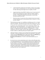
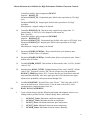
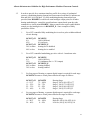
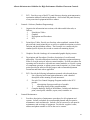
.5
Use controller RC##ST_CO to sequence heating, mixing dampers and cooling stages
as follows:
RC##ST_CO controller output
|------------------------|-------------------------|----------------|
0%
45%
75%
100%
RC##HTG
RC##MAD
RC##CLG
NOTE: If cooling is not available (i.e. RC##CLG_INSTALLED is “No”) then limit
control loop output to values between 0% and 75%.
NOTE: Controller response must be tuned so as to ensure slow smooth operation.
The output must not cause the cooling (DX) or heating (gas) valves to cycle more
than about 6 times per hour.
.6
Separate control over mixed air temperature is often desired. This can be
incorporated into the above scheme by resetting mixed air temperature setpoint
RC##MAT_SP with respect to supply air temperature controller position as follows:
RC##ST_CO
75% or greater
45% or less
RC##MAT_SP
13 degC
23 degC
16
Alberta Infrastructure Guideline for High Performance Modular Classroom Controls
.7
Allow cooling only while RC##SF is ON, AND occupied mode RC##OCCUPIED
is “Yes”, AND outside air temperature RC##OAT is greater than 18 degC. Disable
DX cooling when RC##SF goes OFF, OR RC##OCCUP is “No”, OR RC##OAT
drops below 15 degC. Also disallow cooling during the warm-up/purge phase that is
the first 20 minutes of occupancy.
.8
When enabled for operation, control cooling as follows:
RC##ST_CO
95% or greater
75% or less
RC##CLG
ON
OFF
NOTE: Do not allow more than 6 cycles per hour.
.9
Mixing dampers RC##MAD modulate over controller RC##ST_CO output range of
45% (dampers full return air) up to 75% (dampers full to outside air). OR, if
separate mixed air temperature control is being used, then modulate mixing dampers
RC##MAD over controller RC##MAT_CO output range of 0% (dampers full return
air) up to 100% (dampers full to outside air)
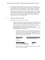
.10
Smoothly limit damper position during warm-up based upon the difference between
classroom space temperature and setpoint as follows:
Space Temp. below Setpoint
3 degC
0.5 degC
Max allowed mixing damper position
0 % (fully closed)
100% (fully open)
.11
To ensure smooth start-up or restart during colder weather, slow the speed of damper
opening such that they cannot go from fully closed to fully open in less than 10
minutes. However, allow them to close quickly if required.
.12
Include an economizer function such that mixing dampers RC##MAD close to
minimum position RC##MAD_MIN when the outside air temperature RC##OAT is
2 degC above space temperature RC##ST. The dampers are to revert to normal
operation when RC##OAT is 1 degC below RC##ST.
.13
If the energy savings option RC##OCCesave is “Yes”, AND outside air temperature
is below 0 degC, then linearly limit damper opening from 100% down to 0% as
RC##OCC_PROB goes from 20% down to 0%.
Note: No need to override in extremely warm weather, this is handled by the normal
economizer function.
.14
Mixing dampers RC##MAD shall go fully closed when supply fan RC##SF is OFF,
OR RC##OCCUPIED is “No”.
17
Alberta Infrastructure Guideline for High Performance Modular Classroom Controls
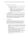
.15
In order to provide for a consistent interface profile for a variety of mechanical
systems, a modulating heating element has been assumed such that 0% indicates no
heat and 100% is for full heat. If a fully modulating heating element has been
provided, then RC##HTG would be an actual analogue output point, for all other
heating methodologies, control the actual hardware outputs based upon the value
contained in a virtual point RC##HTG. Many scenarios also require enable/disable
control over the heating device via RC##HTG_E. Some examples of likely
possibilities follow:
.1
For a PCU controlled fully modulating device such as pulse width modulated
electric heating:
RC##ST_CO
0%
45%
RC##ST_CO
50% or more
40% or less
.2
For a PCU controlled modulating gas valve with a 4-1 turn down ratio:
RC##ST_CO
0%
35%
RC##ST_CO
40% or more
30% or less
.3
RC##HTG
100% (full fire)
0% (minimum fire i.e. 25% output)
RC##HTG_E
heating disabled
heating enabled
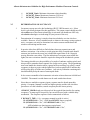
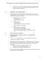
For four stages of heating, a separate digital output is required for each stage.
RC##HTG becomes a virtual point related to the stages as follows:
RC##ST_CO
0 – 11%
11 – 22%
22 – 33%
33 – 44%
.4
RC##HTG
100% (full heat)
0% (no heat)
RC##HTG_E
heating device disabled
heating device enabled
RC##HTG
75 – 100%
50 – 75%
25 – 50%
0 – 25%
Heating Stage
Stage 4, ON @ 98, OFF @ 77
Stage 3, ON @ 73, OFF @ 52
Stage 2, ON @ 48, OFF @ 27
Stage 1, ON @ 23, OFF @ 2
For two stages of heating, a separate digital output is required for each stage.
RC##HTG becomes a virtual point related to the stages as follows:
RC##ST_CO
0 – 20%
20 – 40%
RC##HTG
50 – 100%
0 – 50%
Heating Stage
High fire, ON @ 90, OFF @ 60
Low fire, ON @ 40, OFF @ 10
18
Alberta Infrastructure Guideline for High Performance Modular Classroom Controls
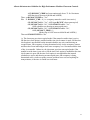
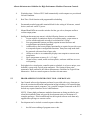
.5
Some heating devices cannot be controlled directly by the PCU. These
generally have self contained controls that maintain the supply air
temperature at some setpoint value RC##SAT_SP. The PCU can be
interfaced to these types of controllers with enable RC##HTG_E and reset
RC##HTG_R. RC##HTG again becomes a virtual point and is used to reset
the supply air temperature setpoint. The values shown in the tables are
included as an examples only. Actual numbers should reflect the needs of the
supplied mechanical equipment.
For a heating device with a high turn down ratio:
RC##ST_CO RC##HTG
RC##HTG_R
0%
100% (full heat)
As required for SAT setpoint of 55
degC
45%
0% (no heat)
As required for SAT setpoint of 22
degC
RC##ST_CO RC##HTG_E
50% or more
heating disabled
35% or less
heating enabled
For a heating device with a 4 -1 turn down ratio:
RC##ST_CO RC##HTG
RC##HTG_R
0%
100% (full heat)
As required for SAT setpoint of 55
degC
35%
0% (minimum heat) As required for SAT setpoint of 30
degC
RC##ST_CO RC##HTG_E
45% or more
heating disabled
30% or less
heating enabled
.16
Ensure heating equipment does not cycle excessively. Typically do not allow more
than about 6 on/off cycles per hour.
.17
An electric coil may be controlled with a solid state relay that is pulse width modulated
under software control.
19
Alberta Infrastructure Guideline for High Performance Modular Classroom Controls
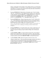
.18
Space relative humidity setpoint RC##RH_SP is calculated as a reset function with
respect to outside air temperature as follows:
RC##RH_SP
15%
30%
RC##OAT
-35 degC or lower
0 degC or higher
.19
Enable humidification device RC##H if the space relative humidity RC##RH is at
least 5%RH below setpoint RC##RH_SP, AND supply fan RC##SF is “On”, AND
occupied mode RC##OCCUPIED is “Yes”. Turn off humidification if there is a
sump alarm via RC##SUMP_HI is “Alarm”, OR RC##RH is above setpoint, OR,
supply fan RC##SF is “Off”, OR occupied mode RC##OCCUPIED is “No”.
.20
For systems with heat reclaim:
.1
Provide software and additional sensors and controls as necessary to ensure
reliable operation of the heat reclaim device under all outside conditions with
minimum downtime for defrosting etc.
.2
As a minimum, provide defrost control based upon outside air temperature as
follows:
.1
Reset RC##HR_DFRSTper with respect to outside air temperature:
OAT (DegC)
-30 of less
-10 or more
.3
3.7
RC##HR_DFRSTPer (hours)
4 hours
12 hours
.2
Set RC##HR_DFRST to “Yes” for a duration of
RC##HR_DFRSTdur minutes every RC##HR_DFRSTper hours
from start of occupied mode.
.3
Do not defrost when outside air temperature is above freezing or
system is in unoccupied mode.
Generally, heat reclaim would be used during occupied mode when outside
air is being introduced into the classroom. However, it is to be disabled
whenever this function would decrease overall energy efficiency or comfort.
For example, if its warm outside but room temperature is warmer still, then
running the reclaim will just warm the incoming air and reduce its ability to
cool the space.
LIGHTING CONTROL
20
Alberta Infrastructure Guideline for High Performance Modular Classroom Controls
.1
For safety and security reasons, lighting must be able to be turned on as soon as there
is any indication of occupancy. Therefore, enable power to lighting contactor
RC##L as soon as occupancy sensor has had a capture (i.e. whenever
RC##OCC_PROB > 30%).
.2
In general, lights are to be operational whenever the space is in occupied mode.
However, when the energy savings option is active, the lights are to be turned off
when the there is no sensed occupancy even if the class is in occupied mode. To
ensure there are no surprises, the lights are pulsed off for 1 second about 5 minutes
before they would be turned off (i.e. as RC##OCC_PROB drops below 20%). This
allows time for any occupants to reinstate normal occupied mode control with a
simple wave of the hand etc.
.3
The logic can be summarized as follows:
If RC##OCC_TMR > 0 {i.e. occupancy manual override is active}
OR RC##OCC_PROB > 30% {occupancy sensor has had 1 capture}
OR (RC##OCCUPIED is “Yes”, AND RC##OCCesave is “No”)
OR (RC##OCCUPIED is “Yes”, AND RC##OCCesave is “Yes”,
AND RC##L_INTMR is OFF) {i.e. not trying to pulse lights off for 1
sec}
Then enable RC##L {i.e. allow lights to be turned on}
Else disenable RC##L {turn lights off}
NOTE: This routine must be scanned very rapidly to ensure lights can be pulsed off
properly, or some other equivalent logic must be created to achieve the same result.
.4
3.8
If daylight harvesting is to be used, then modulate appropriate classroom lights to
maintain light level RC##LL at a setpoint RC##LL_SP adjustable from the
intelligent thermostat’s keypad. Control should be reasonably rapid but timeaveraged so as not to be annoying during fluctuations in daylight caused by cumulous
clouds or the like.
EMERGENCY CONTROL
.1
On detection of failure of intelligent thermostat:
.1
.2
.3
.4
.5
Supply fan shall go into continuous operation.
Exhaust fan shall remain off (occupied or unoccupied mode)
Mixing dampers shall remain fully closed (occupied or unoccupied mode)
Space temperature to be controlled using the mixed air temperature sensor.
Lighting control is to remain unaltered.
21
Alberta Infrastructure Guideline for High Performance Modular Classroom Controls
3.9
CO2 MONITORING AND CONTROL
.1
Each classroom is to be equipped with a carbon dioxide sensor RC##CO2 that
provides the concentration of CO2 in parts per million (PPM).
.2
Inexpensive CO2 sensors may drift over time. Select stable electrochemical devices
that are guaranteed accurate for at least 3 years or ensure devices have some form of
auto zero self calibration function. Even then, the devices should be checked
annually until some confidence in their reliability is attained. Sensors must be able
to be checked and calibrated by operations staff. Devices that need to be sent out for
calibration are not recommended. If special software and/or cables are required for
calibration, provide supplier’s data in the O&M Manual along with retail costs.
.3
Provide a sequence of operation that checks the minimum value of the sensor over a
24 hr period. The sliding window minimum value of CO2 level from the basic data
gathering routines can be used for this check. If the lowest value over the last day
has not been near the atmospheric average, then there is likely a problem with the
sensor so alarm the situation: i.e.
At 10:00 AM:
IF RC##CO2_24min is NOT between 250 and 500
THEN set RC##CO2_FAULT to “alarm” and display this condition on the stat
Once the fault has been corrected a manual reset of RC##CO2_FAULT must also
restore RC##CO2_24min to 499 so as to allow further collection of data starting at a
“normal” value.
.4
As a minimum CO2 must be monitored. However, with the level of controls
necessary to produce the sequences of operation in this guideline, it would also be
possible for the system to control the amount of fresh air introduced into the space.
Since the mechanical system is designed to bring in the amount of fresh air required
for full occupancy, energy savings are possible if the number of students is less than
maximum.
NOTE: Simple breaks in occupancy are already handled by the energy saving option,
i.e. dampers closed and exhaust fan off when no occupancy is sensed.
.5
If control over fresh quantities is being implemented or considered:
.1
For reliability reasons, it is not recommended that any CO2 control routine
increase fresh air quantities above that provided for in the standard
mechanical design. These are already significant and provide for a fully
occupied classroom.
22
Alberta Infrastructure Guideline for High Performance Modular Classroom Controls
3.10
.2
If there is a problem with the sensor (i.e. when RC##CO2_FAULT is in
alarm) disable CO2 control over fresh air quantities and revert to normal
fresh air rates. Only revert to CO2 controlled operation when the alarm has
been manually restored (i.e. the operations staff have corrected the problem)
.3
Setpoint RC##CO2_SP should be conservative. A default value of 800 PPM
would be reasonable and the classroom should not be allowed to exceed 1000
PPM for any significant duration. Only allow setpoints between 750 and 900.
It should be remembered that the whole purpose of these advanced high
performance modular classrooms is to improve environmental conditions for
the students.
.4
Since the mechanical system requires some form of heat reclaim, the amount
of energy to be saved by CO2 control is diminished. Decreasing the flow rate
of fresh air must be balanced by decreases in exhaust rates. On/off control of
the exhaust fan is not an adequate means of control in an occupied classroom,
some form of speed control or modulation is required. This complicates an
already complicated mechanical system.
.5
Decreased air flow through the heat reclaim will make certain types
significantly more efficient, which is beneficial in one respect but it also
makes the unit much more prone to frost and ice buildup. Increased
defrosting may be required. Water pooling in the unit in never a good thing.
ALARM PROGRAMS
.1
Enable mechanical alarm output RC##MALM when any of the following critical
alarms is detected:
.1
.2
.3
.3
Low space temperature via RC##ST < 12 degC.
Mechanical system failure via RC##FAULT.
High sump alarm via RC##SUMP_HI
Intelligent-thermostat (user interface) failure.
.2
It is understood that a simple furnace does not have an available fault output contact
for RC##FAULT but it is assumed that other information will be used in
conjunction with low classroom space temperature to provide similar functionality.
For example: If classroom temperature is below setpoint, and the furnace is
supposed to be firing in low or high fire, and the supply air temperature has been
below 30 degC for the last 15 minutes, then it can safely be assumed there is a
furnace failure and a virtual RC##FAULT value can be set to TRUE.
.3
Display an alarm on the intelligent-thermostat when any of the following non-critical
alarms is detected:
23
Alberta Infrastructure Guideline for High Performance Modular Classroom Controls
.1
.2
RC##CO2_HIALM, high CO2 level via RC##CO2 > 1000 PPM for 30 min
(if CO2 device is available)
RC##CO2_FAULT, CO2 sensor fault (if CO2 device is available)
4.
Documentation
4.1
CONTROLS O&M MANUAL, O&M DISK AND SYSTEM BACKUP
.1
.2
Provide one complete copy of a Controls Operation and Maintenance Manual as
follows:
.1
Divisions :
.1
Controls: Hardware (Configuration/Installation)
.2
Controls: Software (Database/Programming)
.3
Controls: Maintenance
.4
O&M Disk (full manual in electronic format)
.5
Backup Disk
.2
A D-ring binder with two plastic sheet lifters and clear outside overlay
pockets is acceptable.
.3
Binder cover and spine shall display the project title, classroom model, date
of manufacture, serial number and manufacturer’s name. The cover sheet
should also have “DO NOT REMOVE FROM CLASS MECHANICAL
ROOM” in bold red near the bottom. Other information and logos may be
added to the cover as desired.
Controls - Hardware (Configuration/Installation):
.1
Organize the information into sections, with index and divider tabs, as
follows:
.1
Configuration (include explanations of architecture)
.3
System Schematics
.4
PCU
.2
Configuration: Provide a basic configuration diagram showing PCU and
related devices. Provide an explanation of system architecture. Describe
each hardware component and the networks that manage system
communications.
.4
System Schematics: Provide schematics of the mechanical system indicating
point locations, mnemonics and hardware address. Include any wiring details
and equipment schematics showing where and how equipment is interfaced to
PCU. Drawings must be clear and of adequate size for easy reading. If
necessary, fold larger sheets into binder.
24
Alberta Infrastructure Guideline for High Performance Modular Classroom Controls
.5
.3
.4
PCU: Provide a copy of the PCU panel directory showing point mnemonics,
termination addresses and wiring numbers. Also include the panel directory
of any associated equipment/interface cabinet.
Controls - Software (Database/Programming):
.1
Organize the information into sections, with index and divider tabs, as
follows:
.1
Point/object Tables
.2
Graphics
.3
Descriptions and Procedures
.4
PCU
.2
Point/object Tables: Provide two lists that, when combined, contain all the
physical and virtual points/objects as well as a suitable description as to their
function and their database address. The first table is to contain only the
standard profile objects, the second to contain all remaining objects.
.3
Graphics: Provide a hardcopy of recommended graphic display screens.
.4
Descriptions and Procedures: Provide a description of overall control
philosophy. Describe all hardware interlocks with other equipment that may
affect or override action of software control modules. Provide procedures for
operating staff to interface with software control modules, to override system
or component operation, to adjust system control setpoints, etc. Name virtual
points provided in software for this purpose and recommend adjustment
increments and limits where applicable
.5
PCU: Provide the following information separated with coloured sheets:
.1
List of physical and virtual point mnemonics, with a detailed
description of the meaning of each mnemonic.
.2
For each User Control Language Program module in the PCU
provide:
.1
a description of purpose and logic of module.
.2
a hardcopy listing of the program module.
.3
Complete hardcopy listing of the database. Include each hardware
point, virtual point, schedule, report, trend, controller etc.
Controls Maintenance:
.1
Provide a description of maintenance procedures for all equipment and
systems. Include a schedule for recommended planned and preventative
maintenance work and intervals. Include a list of resources to call upon for
maintenance and servicing of equipment. Provide the supplier’s name,
address and phone number as well as the service contact.
25
Alberta Infrastructure Guideline for High Performance Modular Classroom Controls
.5
O&M Disk (full manual in electronic form):
.1
In addition to the hardcopy manuals, provide the Operation and Maintenance
Manuals in electronic form as follows:
.1
O&M data shall be organized exactly as specified for the hardcopy
manuals.
.2
Data shall be compiled into Adobe portable document format and
assembled into as few files as practical. (NOTE: It would be
preferable if there were no more than one file per division.)
.3
Include table of contents links that allow direct access to data as per
the divider tabs required in the hardcopy manual.
.2
.6
4.2
Provide an O&M Disk, in the form of a CD-R. Insert in suitable pouch in
hardcopy manual.
Backups: Provide two (2) complete system backups, each must contain everything
necessary to restore the system to full operation should a catastrophic failure occur.
Also include a jpg, gif or dxf version of the graphic display screen that can be used
by a host system in the future. One package is to be included in the Operation &
Maintenance Manual that will remain in the “Manuals” cabinet in the portable
classroom’s mechanical space. The remaining package is also to be in the cabinet
but in a separate enveloped marked “SYSTEM BACKUP”.
TEACHER’S GUIDE
.1
This guide/pamphlet is to provide casual users such as teachers, custodial staff or
even students, with basic operating information for the user interface (smart
thermostat). It must be written in a clear straight forward manner and be free of
acronyms and technical language. Pictures and graphics should be used as much as
possible to illustrate operations and concepts. Include information as follows:
.1
.2
.3
.4
.5
Display Screen: Show screen layout and displayed information such as room
and outside air temperature, relative humidity, occupancy and operating mode
if applicable. Graphics and/or annotated pictures of actual displays should be
included.
Keypad: Show keypad layout, label each key and provide basic information
as to operation of each key.
Operation: Pictorially and textually guide the casual user through the use of
the basic thermostat menu options such as setting temperature setpoint,
occupancy override and setting light level (if available).
Occupancy Sensing: Provide a clear description of how the occupancy sensor
works, how it is used to determine occupancy and what are the differences
between occupied and unoccupied modes of operation.
Reporting: Describe any reporting features such as alarms, if these are
displayed on the screen.
26
Alberta Infrastructure Guideline for High Performance Modular Classroom Controls
.6
4.3
Green Initiative: Provide a section on the importance of occupant comfort
and indoor air quality. Describe the energy conservation features of the
classroom mechanical equipment.
EMERGENCY PROCEDURES SHEET
.1
This laminated sheet is to provide school maintenance staff with basic trouble
shooting and manual override procedures to be followed under conditions of major
mechanical failure. Items are to include:
.1
.2
.3
Thermostat or user interface failure
- Power problem ?
- Control panel still working?
- Etc.
Control panel failure
- Power problem?
- How to manually position the mixing dampers
- How to manually override the fan
- Etc.
Classroom extreme low temperature
- Control panel or furnace problem?
- How to manually close the outside air dampers
- How to manually engage heating (i.e. gas valve etc) and fan
- Etc.
5.
Controller Hardware and Software
5.1
PROGRAMMABLE CONTROL UNIT (PCU) & INTELLIGENT
THERMOSTAT
.1
The PCU is to be a single stand-alone, custom programmable (NOT simply
configurable), native BACnet controller.
.2
Included interfaces to allow connection to a larger BACnet system via a network to
share information, execute commands, or save/load database and control sequences
from a Central Control Station and/or laptop computer. Provide ALL of the
following:
.1
IEEE 802.3 Ethernet 10/100 Base T, BACnet over IP
.2
EIA-485 @ up to 76.8 kbps, BACnet MS/TP
.3
Serial EIA-232 BACnet PTP 38400kbbs minimum
.3
Memory capacity and point configuration to suit application plus one spare universal
input and one spare analogue output.
27
Alberta Infrastructure Guideline for High Performance Modular Classroom Controls
.4
Watchdog timer. Failure of PCU shall automatically switch outputs to a pre-selected
fail-safe condition.
.5
Real Time Clock function with programmable scheduling.
.6
Permanently marked removable terminal block for the wiring of all sensors, control
devices, network and PCU power.
.7
Manual Hand/Off/Auto override switches for fans, gas valves, dampers and heat
reclaim output points.
.8
Intelligent thermostat (net-sensor) with the following features as a minimum:
.1
Screen capable of continuous display of operating mode, system status as
well as outside and inside air temp to a resolution of 0.5 degC.
.2
Four programmable buttons providing setpoint increase/decrease and
occupied/unoccupied mode operation.
.3
Additional keys and screen display functionality as required to provide access
to setup and sequence configuration functions. Entry into setup mode shall
be protected with some form of pass code.
.4
Ability to set device to continuously display room setpoint or current room
temperature.
.5
Space temperature accuracy of +/- 0.3 degC.
.6
Neutral colour, vented, metal or robust plastic, enclosure with base to cover
wall opening.
.9
Each physical or virtual point, controller point or schedule, is to have a unique, userdefinable, system-wide, logical point mnemonic. The format of these point
mnemonics shall conform to the Alberta Infrastructure Guideline for Logical Point
Mnemonics. Refer to control sequences for other relevant names.
5.2
PROGRAMMING/CONFIGURATION TOOL AND MANUALS
.1
One licensed software development tool must be provided with every classroom to
allow the creation/modification/configuration/saving/reloading of all controller data
bases and custom controls sequences, via a portable computer connected to the PCU.
Include any required interface device/cable/hardware.
NOTE: If many high performance modular classrooms are being provided to one
school division/board, then only provide development tools to a maximum of 3
complete packages. If the board already has the required software tools then only
upgrade these packages to current version.
.2
Development tool to include a control sequence editor that:
.1
has full screen editing of program source code.
28
Alberta Infrastructure Guideline for High Performance Modular Classroom Controls
.2
.3
.4
uses graphic display, drag-and-drop graphic representations and graphic
linking of objects for block language type languages.
automatically changes all program occurrences of a point mnemonic, if that
point mnemonic is changed in data base.
flags undefined point mnemonics if a point is removed from the data base.
.3
Development tool to provide facility to change the Ethernet address of any BACnet
over IP Ethernet enabled classroom controller, as well as have the ability to change
the controller’s BACnet device instance. This is required when networking multiple
BACnet controllers since only one unique BACnet device instance is allowed on a
BACnet network.
.4
Include a development tool user’s manual as well as a programming instruction
manual listing all procedures, functions, operators and reserved words together with
a description and examples of their use in programming.
29
Alberta Infrastructure Guideline for High Performance Modular Classroom Controls
6.
Execution
6.1
OCCUPANCY AND LIGHT SENSORS / DEVICES
.1
Install TWO occupancy sensors, contacts wired in parallel. Sensors to be mounted
high in back corners near the windowed wall. Sensor beams should cross and cover
both possible blackboard locations. Sensing area must not include windows, ceiling
or door out to hallway. Sensitivity to be adjusted so as to trigger on student or
teacher movement but not to respond to normal heating, ventilating, air conditioning
system warm or cold air movement. A single 360 degree, dual technology, ceiling
mounted device may be considered if its performance can meet these requirements.
.2
If daylight harvesting is to be used, then have light sensors look down from ceiling in
area that receives light from the windows, clearstory or other opening.
6.2
.1
For a generic design, light sensors would be located approximately 3m in
from the windows. For a clearstory or light tube, sensor should point down
from ceiling in close proximity to lit area.
.2
Lighting control zones to be coordinated with sensed areas.
.3
Some form of daylight attenuation may be required if class is to be able to be
darkened for AV presentations. These may be manual in nature.
WIRING AND INSTALLATION
.1
Wiring: to CSA C22.2 No. 75-M1983, copper conductor, 600 V RW90 X-link
insulation. 300 V insulation allowed for conductors not entering enclosures
containing line voltage.
.2
120 VAC Control Wiring: minimum #14 AWG.
.3
Low Voltage Field Wiring:
.1
.2
.3
.4
.5
.4
Minimum #22 AWG.
Twisted pairs.
Stranded, except #18 AWG and larger may be solid.
Shielded with drain wire, except for digital input/output wiring carrying less
than 25mA and not installed in tray.
Multi-conductor wiring must have individually twisted and shielded pairs
with a drain wire for each pair. Cable must have overall shield. Maximum 6
pairs.
Plenum rated cable to be FT4 rated.
30
Alberta Infrastructure Guideline for High Performance Modular Classroom Controls
.5
Neatly arranged panduit with snap on covers shall be used to restrain wiring inside
cabinets larger than 300mm square.
.6
Neatly train and cable tie wiring in cabinets smaller than 300 mm square. Adhesive
backed twist ties or adhesive backed cable tie holders are not allowed. Wiring shall
be secured to cabinet back with mountable cable ties fastened with #8 or larger sheet
metal screws.
.7
Each field device shall have its own signal and return wire individually terminated in
the panel. The use of a common return wire or ground for more than one control
point is not allowed.
Plenum rated cable shall be secured to the building structure at intervals not
exceeding 2 meters. Attaching cable to the ceiling support system is not allowed.
.8
.9
6.3
A single continuous non-spliced cable shall be used for connecting each field device.
IDENTIFICATION
.1
Use heat shrink sleeves, with printed or legible hand written identifier, OR factory
coded slip-on identification bead markers or sleeves. Wrap-on adhesive strips are
not allowed.
.2
Size of sleeves to be selected so that they do not slip off when wire is removed from
termination and shaken.
.3
Wiring more than 1 meter in length must be labeled at both ends.
.4
Labels for all system point wiring shall, as a minimum, contain the following
information:
.1
.2
Panel end: panel terminal number or hardware address.
Device end: panel number as well as panel terminal number or hardware
address.
.5
Label panel power supply wiring with the panel connector number.
.6
Label communications port wiring with panel connector number and device name
(e.g. “J1-modem”, “J2-printer”).
.7
Label communications trunk wiring with the panel number, router number etc. to
which the other end of the cable is connected.
Wiring on each side of a terminal block or splice shall be labeled with the
information required for the device end of the wire.
.8
31
Alberta Infrastructure Guideline for High Performance Modular Classroom Controls
.9
Identify all input sensors and output devices, actuators, motors and equipment, with
laminated point tags containing the following information:
.1
.2
.3
.4
6.4
Logical Point Mnemonic
Point Hardware Address and connection terminal identifiers
Associated System Identification
Point Description
GROUNDING
.1
Provide a complete ground system for all PCU equipment, including panels,
conductors, conduit, raceways, connectors and accessories. Grounding shall be by
means of electrical supply conductor bonding method. Separate grounding
conductors not permitted.
.2
Grounding between control panels and field devices shall have a star configuration.
The shield for a field device shall be grounded at the panel only.
.3
The shield for communications wiring must be contiguous throughout its full length
and shall be grounded at one point only. For intelligent thermostats, the ground shall
be at the PCU. Splices shall expose no more than 2cm of unshielded wire.
6.5
SCHOOL INTERFACE CABINET AND TERMINAL STRIP
.1
Supply and install a 250m square, 100mm deep, junction box on the wall, 50mm
above ceiling tile height on the hallway side of the classroom. Install one 10 position
terminal strip and one RJ-45 Ethernet receptacle within the box and affix with #8
screws. Connect this junction box to the PCU cabinet with a 19mm EMT and a
13mm EMT.
.2
School interface strip: Provide separation between the output and input locations.
Wire points to PCU and ensure shield and drain wires are taken back to PCU and
terminated there. Affix a layout sheet on the door inside surface. Label locations as
follows:
Wire pair #1:
Wire pair #2:
Wire pair #3:
Wire pair #4 + shield:
.3
Mechanical Alarm (relay output)
Spare
Time Clock (dry contact input)
EIA-485 School Network (BACnet MS/TP)
(Install termination resistor)
Run communications wiring in 13mm EMT and input/output wiring in 19mm EMT.
32
Alberta Infrastructure Guideline for High Performance Modular Classroom Controls
6.6
TRAINING OF OPERATORS
.1
Provide ½ day factory training courses covering the following:
.1
Tour of mechanical system and overview of system schematics, O&M
Manual and Teacher’s Guide.
.2
Detailed explanation of operating modes and sequences of operation.
.3
Method for changing setpoints, schedules and occupancy override.
.4
Basic trouble shooting.
.5
Very basic description of programming/configuration tool. Provide a list of
all vendor’s in Alberta that can provide post warrantee service on the
supplied controls.
.2
Class size should not be more than 20. Provide a sign off sheet, for inclusion in the
system documentation manuals.
.3
Training must be performed at Alberta location on a fully functional classroom
identical to owner’s units. Provide option for on-site training.
Note: No cost on-site training should be offered to boards that have purchased a
number of high performance modular classrooms. Perhaps one session per 10 units
purchased.
.4
Although not related to controls, training should include a few words on proper site
preparation and classroom installation.
6.7
MISCELLANEOUS
.1
Programming/Configuration tool Manuals, O&M Manual, Disk, Backup Package
and two copies of the Teacher’s Guide to be stored in a lockable cabinet in the
mechanical space. Label cabinet with “MANUALS”. Two copies of the Teacher’s
Guide to be stored in a pouch mounted on the front surface of the cabinet.
END OF GUIDELINE
33
Alberta Infrastructure Guideline for High Performance Modular Classroom Controls
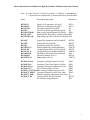
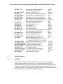
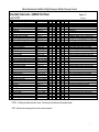
Relocatable Classrooms - SAMPLE Point Sheet
Page 1 of 1
Systems: RC##
No.
1
2
3
4
5
6
7
8
9
10
11
12
13
14
15
16
17
18
19
20
21
22
23
24
Description
Pkg Alarm (Flame Fail etc)
Supply Fan Continuous Operation
Exhaust Fan
Humidifier Solonoid etc.
Gas Valve Low Fire (2 stage)
Gas Valve High Fire (2 stage)
Gas Valve (Modulating)
DX Cooling
Mixed Air Temperature
Supply Air Temperature
Mixed Air Dampers
Relief Air Damper
Net-Sensor / User Interface
Timed Occupancy Manual Override Switch
Space Temperature
Space Relative Humidity
CO2 Concentration
Miscellaneous
Occupancy Sensor
Room Lights
Sump High Level Alarm
Mechanical Alarm
Time Clock
Outside Air Temperature
Spare AI Input
Spare AO Output
Total this System
"Januaryr 2009
RC##
RC##
RC##
RC##
RC##
RC##
RC##
RC##
RC##
RC##
RC##
RC##
Label
FAULT
SF
EF
HF
LF
HF
GV
CLG
MAT
SAT
MAD
RAD
DI
Dc
DO
AI
AO
Ry
Ry
Ry
Ry
Ry
Vm
Ry
Tp
Tp
Dm
Dm
RC##
RC##
RC##
RC##
OCCMOR
ST
RH
CO2
Dc
RC##
RC##
RC##
RC##
RC##
RC##
RC##
RC##
OCCS
L
SUMP-HI
MALM
TC
OAT
Spare1
Spare2
Os
A
A
B
B
Tr
Hr
Co2
Ry
Dc
Ry
Dc
To
Spare
Spare
5
8
7
Group
A
A
B
B
A
A
A
B
A
B
A
A
A
B
B
A
A
A
B
B
Remarks
Include HOA
Include HOA
1st stage of heating: NOTE A (Include HOA)
2nd stage of heating: NOTE A (Include HOA)
Modulating gas valve: NOTE A (Include HOA)
Do not allow activation below 15 degC OAT
Locate in well mixed portion of air stream
Locate in supply duct
Belimo or equivalent actuators (Include HOA)
Belimo or equivalent actuators (Include HOA)
Locate on classroom side of mech room wall
Locate on classroom side of mech room wall
Carbon dioxide concentration PPM
Mount to view blackboard and front desks
N/C contact, Interupt power to switches
Wire to school interface terminal strip
Wire to school interface terminal strip
Mount in fresh air intake
Spare universal input point
Spare universal output point (Include HOA)
4
24
NOTE A : All heating unit safety interlocks to remain. Gas valve type to be determined during system design
NOTE: All points under same group letter must be in same control panel.
1