1
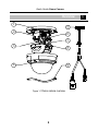
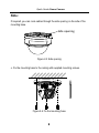
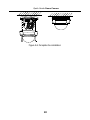
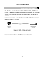
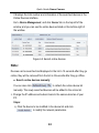
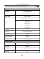
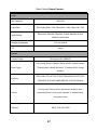
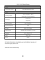
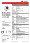
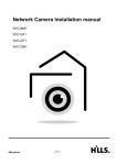
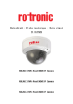
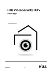
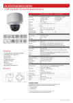
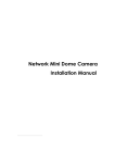
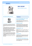
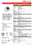
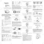
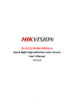
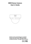
3M IR Dome Camera (4mm) NVC-DF1 Quick Guide V1.3 Quick Guide Dome Camera Table of Contents 1 Overview .......................................................................................................... 3 2 Installation ........................................................................................................ 6 3 Setup using Hill’s NVR ..................................................................................... 11 4 Setup using remote software.......................................................................... 12 5 Specifications.................................................................................................. 16 2 Quick Guide Dome Camera Overview 1 5 2 6 7 3 8 4 9 Figure 1-1 Dome camera overview 3 1 Quick Guide Dome Camera Table 1-1 Physical Description No. Description 1 Mounting Base 2 Horizontal Stand 3 Vertical Stand 4 Bubble 5 Cables 6 IR Led 7 Lens 8 Black Liner 9 Safety Rope 4 Quick Guide Dome Camera Table 1-2 Carton contents Camera Quick Guide Drill template Mounting hardware 3x Expansion screws Hex Key 5 Quick Guide Dome Camera Installation 2 Checklist before you start All carton contents present and are in good conditions. Ensure power supplies are off during installation. Power supply voltage rating as specified in product specifications. Installation environment is as specified. Contact your dealer if product does not function properly. Do not attempt to repair yourself. Wall or mounting platform is strong enough to withstand three times the weight of the camera. 6 Quick Guide Dome Camera Steps: 1. Drill the cable hole and the screw holes in the ceiling according to the supplied drilling template. 1 1 A Drill Template Hole A: for cables routed through the ceiling screw hole 1: for Mounting Base 1 Figure 2-1 Drilling template 2. Loosen the set screws with a hex key (supplied) to remove the bubble. Figure 2-2 Remove the bubble 3. Connect the corresponding cables. 7 Quick Guide Dome Camera Note: If required, you can route cables through the side opening on the side of the mounting base. Side opening Figure 2-3 Side opening 4. Fix the mounting base to the ceiling with supplied mounting screws. Figure 2-4 Fix the mounting base 8 Quick Guide Dome Camera 5. Adjust the surveillance angle. 1). Loosen the tilt adjusting screws, and adjust the tilt angel [0~65], and tighten the tilt adjusting screws. 2). Hold the black liner and rotate it to adjust the pan position [0~360]. 3). Remove the black liner and rotate the camera to adjust the azimuth angle [0~360]. Tilt Adjusting Screw Figure 2-5 3-axis adjustment Note: As the lens has already been factory adjusted to the best imaging effect, you just need to adjust the pan position and tilt position to get the desired surveillance angle. 6. Reinstall the bubble and tighten the screws. 9 Quick Guide Dome Camera Figure 2-6 Complete the installation 10 Quick Guide Dome Camera Setup using Hills’ NVR 3 The Hills Video Security IP cameras (NVC-MB1, NVC-DM1, NVC-DT1 and NVC-DF1) have a pre-loaded protocol that works immediately with Hills Video Security NVRs (NVR-CH4, NVR-CH8 and NVR-CH16) as soon as they are connected. Connect the camera via a network cable to one of the PoE network interface sockets at the back of the NVR. Figure 3-1 NVR – Camera connection Please refer to User Manual of NVR to add and edit a camera. 11 Quick Guide Dome Camera Setup using remote software 4 To view and configure the camera via LAN (Local Area Network), you need to connect the network camera in the same subnet with your PC. Then install the PC Client software to search and change the IP address of the network camera. The following figure shows the cable connection of a network camera and a PC: Figure 4-1 Wiring over LAN Set the IP address of the camera for accessing via LAN. Steps: 1. Use PC client software to detect the online devices. Please refer to the user manual of PC Client software for detailed information. ● Search online devices automatically After launching the PC Client software, it automatically searches the online devices every 15 seconds from the subnet where your computer is located. 12 Quick Guide Dome Camera It displays the total number and information of the searched devices in the Online Devices interface. Go to Device Management, and click Server tab on the top-left of the window, and you can see the online devices listed on the bottom-right of the window. Figure 4-2 Search online devices Note: Devices can be searched and displayed in the list in 15 seconds after they go online; they will be removed from the list in 45 seconds after they go offline. ● Search online devices manually You can also click to refresh the online device list manually. The newly searched devices will be added to the online list. 2. Change the IP address and subnet mask to the same subnet as of your PC. Steps: 1). Click the device to be modified in the device list and click to modify the network parameters. 13 Quick Guide Dome Camera 2). Edit the modifiable network parameters, e.g. IP address and port number. 3). Enter the admin password in the Manager Password field and click to save the changes. Figure 4-3 Modify network parameters Note: ● By default DHCP is enabled. Camera will search for DHCP server for a duration of 30 seconds. If there isn’t DHCP server in the network then use default fixed IP address. ● Default fixed IP address is “10.1.1.1” and Subnet mask is “255.0.0.0”. The default user name is “admin”, and password is “admin”. 14 Quick Guide Dome Camera For accessing the network camera from different subnets, please set the gateway for the network camera after you log in. 15 Quick Guide Dome Camera Specifications Camera Image Sensor Min. Illumination 1/3" Progressive Scan CMOS 0.07Lux @ (F1.2, AGC ON) ,0 Lux with IR Shutter Speed 1/3 s to 1/100,000 s 4mm@ F2.0 (2.8mm, 6mm optional) 2048 × 1536: Lens Angle of view: 70° 1920 × 1080: Angle of view: 79° Lens Mount M12 Day &Night IR cut filter with auto switch Digital Noise Reduction 3D DNR Wide Dynamic Range Digital WDR Angle Adjustment Pan:0° - 355°, Tilt: 0° - 65° Compression Standard Video Compression H.264/ MJPEG H.264 Type Main Profile Video Bit Rate 32 Kbps – 12 Mbps Dual Stream Yes 16 5 Quick Guide Dome Camera Image Max. Resolution Frame Rate Image Settings 2048×1536 50Hz: 20fps (2048 × 1536), 25fps (1920 × 1080), 25fps (1280 × 720) Rotate mode, Saturation, Brightness, Contrast adjustable by client software or web browser Backlight compensation Yes, zone optional ROI Support Network Network Storage NAS (Support NFS,SMB/CIFS) Line Crossing, Intrusion Detection, Motion detection, Dynamic analysis, Alarm Trigger Tampering alarm, Network disconnect , IP address conflict, Storage exception TCP/IP,ICMP,HTTP,HTTPS,FTP,DHCP,DNS,DDNS,RTP,RTSP,RTCP, Protocols PPPoE,NTP,UPnP,SMTP,SNMP,IGMP,802.1X,QoS,IPv6,Bonjour One-key reset, Flash-prevention, dual stream, heartbeat, mirror, General password protection, privacy mask, watermark, IP address filtering, Anonymous access Standard ONVIF, PSIA, CGI, ISAPI 17 Quick Guide Dome Camera Interface Communication Interface 1 RJ45 10M/100M Ethernet interface General -30 °C – 60 °C (-22 °F – 140 °F) Operating Conditions Humidity 95% or less (non-condensing) 12 V DC ± 10% Power Supply PoE (802.3af) Power Consumption Max. 7 W with IR on Ingress Protection level IP66 IR Range Impact Protection Approx. 10 to 30 meters IEC60068-2-75Eh, 50J; EN50102, up to IK10 Dimensions Φ111 × 82 (4.4” × 3.2”) Weight 500g (1.1 lbs) Part No S47091 For further information, including full user and installation manual, and technical support please visit: www.hills.com.au/videosecurity 18