1
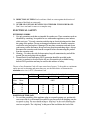
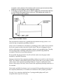
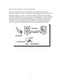
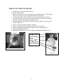
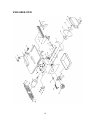
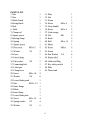
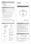
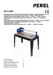
FLORCRAFTTM PRODUCT MANUAL SKU NUMBER 709-4242 SERIAL NUMBER: __________ CAUTION: FOR YOUR OWN SAFETY READ INSTRUCTION MANUAL COMPLETELY AND CAREFULLY BEFORE OPERATING THIS 7” TILECUTTING MACHINE SPECIFICATIONS Voltage: 120V AC Cycle: 60Hz, single phase Current draw full load: 3.75 amp Current draw no load: 1.35 amp Motor No-load speed: 3,600 rpm Arbor Size: 5/8” Table Dimensions: 15-1/2” x 15-1/8” Angle Capability: 0-45 Degrees Depth of Cut: 1.34” Weight: 32 lbs ALWAYS WEAR ANSI Z87.1 APPROVED EYE PROTECTION! 7” TILE CUTTING MACHINE . Operation . Parts List and Diagram SAVE THIS MANUAL FOR FUTURE REFERENCE. For questions or problems please call our customer service line at (888) 315-3080 M-F 8-5 Central Time. 1 TECHNICAL SPECIFICATIONS Model Current draw full load Current draw no load Input voltage Frequency (Hz) No Load Speed (rpm) Maximum Continuous working period (min.) Minimum resting period (minutes) Motor isolation class Max Cutting height Work Table Dimensions (inch) Weight WTC180 3.75 amp 1.35 amp 120 V 60 Hz 3600 rpm 10 5 Type B 1.34” 15-1/2” x15-1/8” 32LBS PRODUCT USE This tile-cutting machine is designed for cutting small and medium size tile. It is equipped with a diamond-cutting blade for excellent cutting results. The stainless steel worktop tilts up to 45 degrees for cutting desired angles. KNOW YOU SAW Before using this saw, read the instructions completely. Pay particular attention to all safety rules. Practice the maintenance instructions to ensure your machine always operate efficiently and safely. Prior to operating this machine, familiarize yourself with the controls and make sure you know how to stop it quickly if needed. Save this user’s manual and other documents supplied with this machine for future reference. 2 GENERAL SAFETY RULES WARNING! Read and understand all instructions. Failure to follow all instructions listed below may result in electrical shock, fire and/or serious personal injury. 1. 2. 3. 4. 5. 6. 7. 8. 9. 10. 11. 12. 13. 14. 15. 16. 17. 18. 19. KEEP GUARDS IN PLACE and in working order. REMOVE ADJUSTING KEYS AND WRENCHES. Form habit of checking to see that keys and adjusting wrenches are removed from tool before turning it on. KEEP WORK AREA CLEAN. Cluttered areas and benches invite accidents. DON’T USE IN DANGEROUS ENVIRONMENT. Don’t use power tools in damp or wet locations, or expose them to rain. Keep work area well lighted. KEEP CHILDREN AWAY. All visitors should be kept safe distance from work area. MAKE WORKSHOP KID PROOF with padlocks, master switches, or by removing starter keys. DON’T FORCE TOOL. It will do the job better and safer at the rate for which it was designed. USE RIGHT TOOL. Don’t force tool or attachment to do a job for which it was not designed. USE PROPER EXTENSION CORD. Make sure your extension cord is in good condition. When using an extension cord, be sure to use on heavy enough to carry the current your product will draw. An undersized cord will cause a drop in line voltage resulting in loss of power and overheating. Table below shows the correct size to use depending on cord length and nameplate ampere rating. If in doubt, use the next heavier gage. The smaller the gage number, the heavier the cord. WEAR PROPER APPAREL. Do not wear loose clothing, gloves, neckties, rings, bracelets, or other jewelry which may get caught in moving parts. Nonslip footwear is recommended. Wear protective hair covering to contain long hair. ALWAYS USE SAFETY GLASSES. Also use face or dust mask if cutting operation is dusty. Everyday eyeglasses only have impact resistant lenses, they are NOT safety glasses. SECURE WORK. Use clamps or a vise to hold work when practical. It’s safer than using your hand and it frees both hands to operate tool. DON’T OVERREACH. Keep proper footing and balance at all times. MAINTAIN TOOLS WITH CARE. Keep tools sharp and clean for best and safest performance. Follow instructions for lubricating and changing accessories. DISCONNECT TOOLS before servicing: when changing accessories, such as blades, bits, cutters, and the like. REDUCE THE RISK OF UNINTENTIONAL STARTING. Make sure switch is in off position before plugging in. USE RECOMMENDED ACCESSORIES. Consult the owner’s manual for recommended accessories. The use of improper accessories may cause risk of injury to persons. NEVER STAND ON TOOL. Serious injury could occur if the tool is tipped or if the cutting tool is unintentionally contacted. CHECK DAMAGED PARTS. Before further use of the tool, a guard or other part that is damaged should be carefully checked to determine that it will operate properly 3 20. DIRECTION OF FEED. Feed work into a blade or cutter against the direction of rotation of the blade or cutter only. 21. NEVER LEAVE TOOL RUNNING UNATTENDED. TURN POWER OFF. Don’t leave tool until it comes to a complete stop. ELECTRICAL SAFETY EXTENSION CORDS 1. Use only extension cords that are intended for outdoor use. These extension cords are identified by a marking “Acceptable for use with outdoor appliances; store indoors while not in use.” Use only extension cords having an electrical rating not less than the rating of the product. Do not use damaged extension cords. Examine extension cord before using and replace if damaged. Do not abuse extension cords and do not yank on any cord to disconnect. Keep cord away from heat and sharp edges. Always disconnect the extension cord form the receptacle before disconnecting the product from the extension cord. 2. Warning – To reduce the risk of electrocution, keep all connections dry and off the ground. Do not touch plug with wet hands. 3. Ground Fault Circuit Interrupter (GFCI) protection should be provided on the circuit(s) or outlet(s) to be used for the tile saw. Receptacles are available having built-in GFCI protection and may be used for this measure of safety. The use of any Extension Cord will cause some loss of power. To keep this to a minimum and to prevent overheating and motor burn out; use the table below to determine the minimum wire size (A.W.G.) Extension Cord. Ampere Rating More Than 0 6 10 12 Not More Than 6 10 12 16 Volts 120V 25ft. Total length of cord in feet 50ft. 100ft. 150ft. AWG 18 18 16 14 16 16 16 12 16 14 14 -- 14 12 12 -- POSITION OF TILE SAW 1. To avoid the possibility of the appliance plug or receptacle getting wet, position tile saw to one side of a wall mounted receptacle to prevent water from dripping onto the receptacle or plug. The user should arrange a “drip loop” in the cord connecting the saw to a receptacle. The “drip loop” is that part of the cord below the level of the 4 receptacle, or the connector if an extension cord is used, to prevent water traveling along the cord and coming in contact with the receptacle. 2. If the plug or receptacle does get wet, DON’T unplug the cord. Disconnect the fuse or circuit breaker that supplies power to the tool. Then unplug and examine for presence of water in the receptacle. GROUNDING INSTRUCTIONS This tool should be connected to a grounded metal permanent wiring system: or to a system having an equipment-grounding conductor. In the event of a malfunction or breakdown, grounding provides a path of least resistance for electric current to reduce the risk of electric shock. This tool is equipped with an electric cord having an equipment-grounding conductor and a grounding plug. The plug must be plugged into a matching outlet that is properly installed and grounded in accordance with all local cords and ordinances. Do not modify the plug provided- if it will not fit the outlet, have the proper outlet installed by a qualified electrician. Improper connection of the equipment-grounding conductor can result in a risk of electric shock. The conductor with insulation having an outer surface that is green with or without yellow stripes is the equipment-grounding conductor. If repair or replacement of the electric cord or plug is necessary, do not connect the equipment-grounding conductor to a live terminal. Check with a qualified electrician or service personnel if the grounding instructions are not completely understood, or if in doubt as to whether the tool is properly grounded Use only 3-wire extension cords that have 3-prong grounding plugs and 3-pole receptacles that accept the tool’s plug. 5 Repair or replace damaged or worn cord immediately. This tool is intended for use on a circuit that has an outlet that looks like the one illustrated in Sketch A in Figure 1. The tool has a grounding plug that looks like the plug illustrated in Sketch A in Figure 1. A temporary adapter, which looks like the adapter illustrated in Sketches B and C, may be used to connect this plug to a 2-pole receptacle as shown in Sketch B if a properly grounded outlet is not available. The temporary adapter should be used only until a properly grounded outlet can be installed by a qualified electrician. The green-colored rigid ear, lug, and the like, extending from the adapter must be connected to a permanent ground such as a properly grounded outlet box. 6 SPECIFIC SAFETY RULES FOR THE 7” TILE CUTTING MACHINE 1. Prior to starting the saw, verify that the supply voltage and the motor voltage match. The motor voltage is 120V at 60 Hz. 2. Use only grounded power outlets (three prong receptacles). Do not defeat the grounding feature by removing the grounding plug from the power cord. 3. Avoid using overly long extension cords. See “Extension Cords” for extension cord recommendations based on amperage and length. 4. Always place the saw on a flat secure surface to prevent movement during cutting operations. Make sure the rubber feet inserts are in place and securely positioned. 5. Make sure the blade guard is in place. Do not remove it for any reason. 6. Inspect the diamond saw blade prior to use to insure it is free of cracks. Replace cracked blade immediately. DO NOT USE if cracked. 7. Prior to plugging the saw into a power outlet, make sure the “On/Off” switch is in the “Off” position. 8. Keep the power cord away from the blade and/or the tile being cut. 9. While cutting, do not put side pressure on the saw blade. The blade can break if too much side pressure is applied. Do not feed the material too quickly. Do not force the work piece against the blade. 10. Do not use the saw if the “On/Off” switch is broken or if the power supply cord is cut or damaged in any way. 11. Do not use the saw to cut tile unless the proper amount of water is in the tray. The water cools the blade and prevents the formation of cracks in the blade. 12. Never cut more than one piece at a time. Or stack more than one tile on the saw table at a time. PROPER OPERATION AND SAFETY A. Saw Set-up The 7” Wet Tile Saw comes assembled with a 7” diamond wet blade already in place. The only assembly required by the owner is the attachment of the four (4) rubber stabilizing feet. To install, twist the pointed ends into the holes on the bottom edges of the machine until the shoulders of the feet fit tightly against the saw. The rubber feet keep the saw from slipping during operation. B. Operating the Saw 1. The original OEM diamond blade for the saw is a 7” wet cutting blade. The saw will accept any wet cutting blade 6 inches or greater up to 7 inches with a 7/8 inch arbor. See blade replacement instructions for specifics on how to change blades. 2. With the power supply cord unplugged, FILL THE WATER TRAY prior to use. The water tray is located under the blade assembly and is easily moved by simply sliding the tray out until it hits the blade assembly cover. Fill the tray up to at 7 least the “Minimum” hash mark but not over the “Maximum” hash mark. Slide the tray back under the blade assembly. 3. When cutting tile, follow these instructions for safe use of the saw. • • • • Always use a guide while cutting tile. DO NOT cut freehand. For parallel cuts, use the fence provided to guide the tile into the blade. Always position the tile to be cut so that the largest part of the tile is between the fence and the blade. This will give the operator the most secure pushing surface and reduce the chance of binding. For a 45° angle cut, use the plastic jig enclosed to guide the tile along the fence. For bevel cuts from 0° to 45°, tilt the worktable the appropriate degree. Start by unloosening the knob on the front of the saw. Tilt the table to the desired degree using the scale located on the front as a guide. Tighten the knob to secure the table. 4. IMPORTANT Limit continual use to 10 MINUTES. Allow the saw to cool down for 5 MINUTES before resuming cutting tile. 5. Periodically check the water supply in the water tray and refill as needed. Do not cut tile without water. MAINTENANCE 1. Prior to performing any maintenance, unplug the saw from the power supply. 2. Clean out the water tray periodically to remove sediment. 3. Clean the ventilation slots by either brushing the accumulated dust away or by using compressed air o blow the slots clean. Wear safety goggles when using compressed air. TROUBLE SHOOTING 1. If the saw does not start when the switch is moved to the “On” position, possible problems include an interruption in the power supply. Check the following: Is the saw plugged into an electrical outlet? Is the outlet receiving power from the circuit box? Is the “On/Off” switch operational? 2. The saw runs hot even under a no load condition. Check the following: Are the ventilation slots free and clear of debris and dust? 8 REPLACING THE SAW BLADE 1. Unplug the saw from the electrical outlet 2. Remove the water tray. 3. Remove the blade cover by removing the two (2) Phillips screws. The front and back cover will drop down exposing the blade and arbor shaft. 4. To loosen the blade, attach a 19mm open-end wrench on the nut. Attach an adjustable wrench on to the end of the arbor shaft. The arbor shaft is squared at the end to facilitate attaching the adjustable wrench. 5. While holding the arbor shaft firm, unloosen the nut with the 19mm open-end wrench. (Figure A) 6. Remove the lock nut and the flange. (Figure B) 7. Remove the blade and position the new blade on the arbor shaft. 8. Replace the flange paying particular attention to the rotation direction. 9. Install and tighten the lock nut 10. Install the back and front cover for the blade and tighten the Phillips screws. Flange Seat Arbor shaft Blade Flange cap Nut (19mm) 9 EXPLODED VIEW 10 PARTS LIST 1. Nut 2. Nut 3. Blade Guard 4. Riving Knife 5. Bolt 6. Table 7. Clamp rod 8. Square spacer 9. Moving clamp 10. Spring 11. Square spacer 12. Hex screw 13. Washer M5 x12 Ф5 14. Fence 15. Fixed clamp 16. Flat washer 17. Connecting bolt 18. Cotter pin 19. Clamp lever 20. Screw 21. Washer Ф8 M4 x 10 Ф4 22. Lower blade guard 23. Nut M12 x 1.5 24. Outer flange 25. Blade 26. Inner flange 27. Lower blade plate M5 x 12 28. Screw 29. Spring washer Ф5 30. Washer Ф5 1 1 1 1 1 1 1 1 1 1 1 2 2 31. Plate 32. Nut 33. Frame 34. Screw 35. Carry handle 36. Screw 37. Cord storage 38. Nut 39. Knob 40. Bolt 41. Motor 42. Screw 43. Frame 1 1 44. Star Washer 45. Strain relief 1 1 1 1 2 8 46. Cable and Plug 47. Key safety switch 48. Plate 49. Water tank 1 1 1 1 1 1 4 4 6 11 M4 x 8 M5 x 8 M6 M6 x 12 M4x6 Ф4 1 1 1 2 1 2 2 2 2 2 1 6 1 4 1 1 1 1 1