1
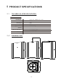
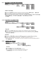
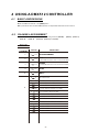
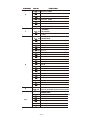
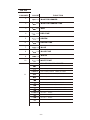
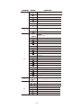
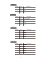
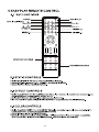
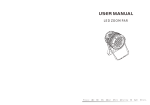
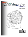
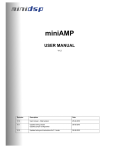
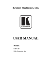
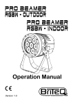
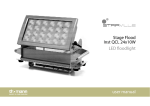
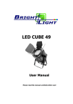
USER MANUAL 4X10W RGBW 4 IN 1 Led Wireless Battery Zoom Light P l e ase R ead O v e r T h i s M anua l B e f o re O per a t ing T he L ig h t F i xtur e Attention! “AC INPUT” is the charging interface. When charging, the fixture must be “ TURN OFF”. lease do not work in the AC unless it’s under emergency. If it works in the AC for a long time, the charger and batteof the fixture will overwork , bring out a lot of heat and cause a risk of explosion. If the batter y runs out, then connect to the AC. It needs 10 minutes to recover to the normal operation. When in the outdoor, please must not use AC to operate the fixture. The waterproof and dustproof rate of this fixture is IP44. Please avoid the leakage of electricity and the danger of electric shock . 1 PRODUCT SPECIFICATIONS 1.1 TECHNICAL SPECIFICATIONS LED MODULE LED MODULE: Voltage Zoom Range Power Type of bettery IP Rating Operation Temperature 4pcsx10W(RGBW 4 in 1 LED) 24VDC 7~60º 40W Lithium Battery IP 44 0℃~35℃(operating) 0℃~35℃(startup) Dimensions Weight 1.2 270x160x160mm 4.5Kg DIMENSIONS ·1· 1.3 SAFETY WARNING IMPORTANT 【ALWAYS READ THE USER MANUAL BEFORE OPERATION. 】 【PLEASE CONFIRM THAT THE POWER SUPPLY STATED ON THE PRODUCT IS THE SAME AS THE MAINS POWER SUPPLY IN YOUR AREA.】 ● This product must be installed by a qualified professional . ● Always operate the equipment as described in the user manual . ●A minimum distance of 0.5m must be maintained between the equipment and combustible surface. ● The product must always be placed in a well ventilated area. ● Always make sure that the equipment is installed securely. ● Do not stand close to the equipment and stare directly into the LED light source. ● Always disconnect the power supply before attempting maintenance. ●Always make sure that the supporting structure ● The earth wire must always be connected to the ground. ● Do not touch the power cables if your hands are wet. ATTENTION ● Do not operate in a sealed enclosure with insufficient air flow ● Do not operate in an environment with temperatures in excess of 45deg. C . ● Do not operate store in close proximity to source of fire. ● Always charge with supplied charger ● Do not charge for more than 24 hours ● Always turn off battery storage switch when storing for longer than 7 days ● Always store with full load ● Always charge with flightcase open ● Always carry out one full discharge and charge cycle every 3 months ● Always store in a dry environment away from direct sunlight 2 GETTING STARTED 2.1 OPERATING POSITION ● This lighting fixture is powered using a Lithium Battery which requires that the correct product orientation is always maintained for operation. ·2· ZOOM RANGE (7~60º) Zoom Range 60º Zoom Range 7º 2.2 BATTERY CHARGING INPUT Attention! “AC INPUT” is the charging interface. When charging, the fixture must be“ TURN OFF”. lease do not work in the Cunless it’s under emergency. If it works in the AC for a long time, the charger and batteof the fixture will overwork , bring out a lot of heat and cause a risk of explosion. If the batter y runs out, then connect to the AC. It needs 10 minutes to recover to the normal operation. When in the outdoor, please must not use AC to operate the fixture. The waterproof and dustproof rate of this fixture is IP44. Please avoid the leakage of electricity and the danger of electric shock . 100~240V AC CHARGING INPUT L 1 2 Charging Input 100~240V AC CHARGING INPUT ● Do not connect DMX ● Only for specified charger(in flight case or single charger) ● Do not connect any other data cables ·3· N G 2.3 GENERAL OPERATION ON/OFF Switch Zoom Knob IR Receiver Power Status GREEN: >70% YELLOW: >20% RED: EMPTY 2.3.1 POWER STATUS ● During operation, the Power Statuas indicator will indicate the amount of battery power that is remaining. The battery should be recharged when RED is shown. ● During charging, the Power Statuas indicator will indicate the amount of battery power that has been charged to the battery. When the battery is fully charged the GREEN LED will immediately switch off. ● In the event that the battery storage switch is OFF, it is not possible to charge the battery. In this case, when the mains power is connected to the fixture, the Power Statuas indicator will show GREEN for 30 seconds and then fade out. This shows that electrical contact has been made between the lighting fixture and the battery charging system. The Battery Storage Swicth must be ON in order to charge the battery. ● In order to check the current status of the battery, the battery charging system should be turned OFF. The fixture can then be turned ON using the EVENT ON/OFF button and the Power Statuas can be checked. 2.3.2 ON/OFF SWITCH ● Press the SWITCH ON/OFF button for 3 seconds to turn on/off lighting fixture (when BATTERY SWITCH is ON) ● SWITCH ON/OFF button indicator LED when showing constant RED indicates lighting fixture is power ON ( when slowly flashing indicates that DMX data is successfully received) 2.4 OTHER OPERATIONS 1 POWER ON/OFF 2 100~220V AV CHARGING INPUT 3 DISPLAY 2.4.1 ANTENNA RELEASE ● When releasing support antenna with hand 2.4.2 BATTERY SWITCH ● ON for operation/charging ● OFF for storage (>7 days) ● OFF for maintenance ● Always use the Battery Switch when storing for more than 7 days ● Battery Switch must be ON for operation and charging ·4· 3 USING THE MENU 3.1 BASIC The LED fixture is mounted with a LCD display And 4 control buttons. MENU ENTER UP DOWN scroll through the main menu or return to the main menu ENTER enter the currently selected menu or confirm the current function value scroll 'UP' through the menu list or increase the value of the current function scroll 'DOWN' through the menu list or decrease the value of the current function MENU 3.2 MENU MENU STAT RED GREN BLUE WHITE STRB AUTO AT.01 R.(0~255) G.(0~255) B.(0~255) B.(0~255) S.(0~20) AT.10 PR.01 PR.10 RUN DMX SLAV ADDR D.(001~512) PERS TOUR Tr16 ARC.1 AR1.D ARC.2 AR2.D AR2.S HSV SET KEY UPLD REST COLOR DIM CURV DERR EDIT ON OFF PASS PASS OFF RGBW UC DIM4 DIM1 DIM2 DIM3 O FF OFF Cv1 Cv2 Cv3 O FF SAVE BLAK SLCK O FF OFF ON STRB O FF SPEC CLAS LIFE LONG NORM PR.01 SC.01 PR.10 SEND REST SC.30 ·5· RED GREN BLUE WHITE STRB TIME FADE R.(0~255) G.(0~255) B.(0~255) W.(0~255) S.(0~20) T.(0~255) F.(0~255) END END CAL **** CAL1 WH.01 CAL2 RGB.W ON OFF NO YES OK WH.11 WDMX ACTI REST 3.3 RED GREN BLUE R.(0~255) G.(0~255) B.(0~255) RED GREN BLUE R.(0~255) G.(0~255) B.(0~255) EDIT STATIC COLOUR MENU STAT Red Green Blue (0~255) (0~255) (0~255) White Strob (0~255) (0~20) 【STATIC COLOUR】 ● Combine 【Red】, 【Green】,【Blue】and【White】 to create an infinite range of colors (0-255) ● Set the value of the 【Strobe】 (0-20Hz) 3.4 ACTIVATING AUTO PROGRAMS MENU AUTO AT.01 AT.10 PR.01 PR.10 【AUTO】 ● Select the target【AUTO】 program and press【ENTER】. ● Programs【AT.01】to【AT.10】are fully pre-programmed and will not be altered by changes in【EDIT 】mode. ● Programs 【PR.01】to【PR.10】are fully pre-programmed and can be edited in 【EDIT 】mode. 3.5 DMX512 SETTINGS MENU DMX D(001~512) 【DMX】 ● Enter the【DMX】mode to set the DMX ADDRESS. 3.6 RUN MODE MENU RUN DMX SLAV 【RUN 】 ● Enter the【RUN 】mode to set working mode. ● 【DMX】 mode is for using the DMX512 controller to control the fixtures. ● 【SLAV】 mode is for Master -- Slave operation. ·6· 3.7 PERSONALITY MENU PERS 【PERSONALITY】 TOUR ARC.1 AR1.D HSV BLOC ● Enter the【PERSONALITY】mode to select DMX mode:【TOUR】,【TR16】, 【ARC.1】,【AR1.D】,【ARC.2】,【AR2.D】,【AR2.S】or【HSV】 3.8 SPECIAL SETTINGS SET KEY UPLD REST COLOR DIM CURV DERR ON OFF PASS PASS END END OFF RGBW UC DIM4 DIM1 DIM2 DIM3 O FF OFF Cv1 Cv2 Cv3 O FF SAVE BLAK SLCK O FF OFF ON STRB O FF SPEC CLAS LIFE SEND REST LONG NORM 【SETTING】 【KEY】 ● Enter the【KEY】mode to select whether the access password is on or off. ● When the fixture is set as PASS 【ON】, after 30 seconds or turn on the fixture next time, the fixture will need an access password to enter the display menu control. Note: The factory access password is【UP】+【DOWN】+【UP】+【DOWN】, then press 【ENTER】to confirm the access. ● Select【UPLD】to upload the custom programs from the current MASTER unit to the SLAVE units. ● In order to activate the upload function the password must be entered. ● Password is the same as the main access password. ● When uploading the MASTER and SLAVE units will display YELLOW. ● If an error occurs when uploading the MASTER and/or SLAVE units will display RED. ● On successful uploading of the custom programs the MASTER and SLAVE units will display GREEN. ● In order to reset custom modes to default values select 【REST】. ● 【COLOR】 is for activate/unactivate the color calibration functions. When 【RGBW】is selected, on RGBW = 255,255,255, 255 the color is displayed as calibrated in CAL2 -- RGBW. When【COLOR】 is set 【OFF】, on RGBW = 255,255,255,255 the RGBW values are not adjusted and the output is most powerful. When [UC] is selected, the RGB output are adjusted to a standard preset universal color which balances fixtures from different generations.. ● 【LIFE】BATTERY LIFE ; LONG for extended battery operation (approx. 10hrs), NORM for standard battery operation (approx. 8hrs). ·7· 3.9 EDITING CUSTOM PROGRAMS MENU EDIT PR.01 SC.01 PR.10 SC.30 Red Green Blue White Strobe Time Fade (0~255) (0~255) (0~255) (0~255) (0~20) (0~255) (0~255) 【EDIT CUSTOM】 ● Enter the【EDIT 】mode to edit the custom programs【PR.01】to 【PR.10】. ● Each custom program has 30 steps that can be edited. ● Each step allows the creation of a scene using RED 【Red】, GREEN 【Green】, BLUE 【Blue】, STROBE 【Strobe】, TIME【Time】 & FADE 【Fade】. 3.10 WHITES CALIBRATION MENU CAL CAL1 WT01 WT02 CAL2 RGBW Red Green Blue (0~255) (0~255) (0~255) Red Green Blue (0~255) (0~255) (0~255) WT11 【CAL1】 ● Enter the 【CAL1】to select white color of different color temperature. ● There are 11 pre-programmed White colors can be edited by using 【Red】, 【Green】&【Blue】. 【CAL2】 ● Enter the 【CAL2】to adjust the RGB parameter to make different whites. ● When the new setting is activated, the DMX controller choose RGB = 255,255,255, the white color will be made by the actual RGB values on the 【CAL2】. 3.12 WDMX SETTINGS MENU WDMX ON OFF NO YES ACTI REST OK 【WDMX】 ● Enter 【WDMX】menu to change WDMX settings ● Enter the 【ACTI】 menu to turn ON/OFF WDMX functionality ● Enter the【REST】 menu to reset the WDMX pairing (note that only when the WDMX receiver card is reset can it be paired with a new WDMX transmitter card) ·8· 4 USING A DMX512 CONTROLLER 4.1 BASIC ADDRESSING ● Set the DMX512 address in the【DMX】menu. ●It is possible to have the same DMX address or independent addresses for each fixture. 4.2 CHANNEL ASSIGNMENT ● Note:This product has six DMX512 channel configurations:【TOUR】,【TR16】,【ARC . 1】, 【AR1 .D】,【ARC .2】,【AR2.D】,【AR2.S】and【HVS】. TOUR CHANNEL VALUE 1 0 255 2 0 255 3 0 255 4 0 255 5 0 255 MASTER DIMMER RED 0 6 FUNCTION 5 (or STEP TIME when CUS.01-CUS.10 in CH10 is activated) GREEN (or FADE TIME when CUS.01-CUS.10 in CH10 is activated) BLUE White NO FUNCTION 11 30 RED100%/GREEN UP/BLUE0% 31 50 RED DOWN/GREEN 100%/BLUE0% 51 70 RED 0%/GREEN 100%/BLUE UP 71 90 RED 0%/GREEN DOWN/BLUE 100% 91 110 RED UP/GREEN 0%/BLUE100% 111 130 RED100%/GREEN 0%/BLU EDOWN 131 150 RED100%/GREEN UP/BLUE UP 151 170 RED DOWN/GREEN DOWN/BLUE 100% 200 RED100%/GREEN 100%P/BLUE100% 171 201 205 W H I T E 1:3 2 0 0 K 206 210 W H I T E 2:3 4 0 0 K 211 215 W H I T E 3:4 2 0 0 K 216 220 W H I T E 4:4 9 0 0 K ·9· CHANNEL 6 VALUE FUNCTION 221 225 W H I T E 5:5 6 0 0 K 226 230 W H I T E 6:5 9 0 0 K 231 235 W H I T E 7:6 5 0 0 K 236 240 W H I T E 8:7 2 0 0 K 241 245 W H I T E 9:8 0 0 0 K 246 250 W H I T E 1 0:8 5 0 0 K 251 255 W H I T E 1 1:1 0 0 0 0 K STROBE 0 7 11 10 NO FUNCTION 2 5 5 1~20Hz AUTO 8 9 0 40 NO FUNCTION 41 50 AUTO 1 51 60 AUTO 2 61 70 AUTO 3 71 80 AUTO 4 81 90 AUTO 5 91 100 AUTO 6 101 110 AUTO 7 111 120 AUTO 8 121 130 AUTO 9 131 140 AUTO 10 141 150 PR.01 151 160 PR.02 161 170 PR.03 171 180 PR.04 181 190 PR.05 191 200 PR.06 201 210 PR.07 211 220 PR.08 221 230 PR.09 231 255 PR.10 AUTO SPEED ADJUSTMENT 0 255 When using CH10,AUTO01-AUTO10, this function activated DIMMER SPEED 0 10 9 PRESET DIMMER SPEED FROM DISPLAY MENU 10 29 LINEAR DIMMER 30 69 NON LINEAR DIMMER 1(fastest) 70 129 NON LINEAR DIMMER 2 130 189 NON LINEAR DIMMER 3 190 255 NON LINEAR DIMMER 4(slowest) ·1 0· TR16 CHANNEL VALUE FUNCTION 1 0 255 MASTER DIMMER 2 0 255 MASTER DIMMER FINE 3 0 255 RED 4 0 255 RED FINE 5 0 255 GREEN 6 0 255 GREEN FINE 7 0 255 BLUE 8 0 255 BLUE FINE 9 0 255 WHITE 10 0 255 WHITE FINE COLOR MACRO&WHITE 11 0 10 NO FUNCTION 11 30 RED100%/GREEN UP/BLUE0% 31 50 RED DOWN/GREEN 100%/BLUE0% 51 70 RED 0%/GREEN 100%/BLUE UP 71 90 RED 0%/GREEN DOWN/BLUE 100% 91 110 RED UP/GREEN 0%/BLUE100% 111 130 RED100%/GREEN 0%/BLU EDOWN 131 150 RED100%/GREEN UP/BLUE UP 151 170 RED DOWN/GREEN DOWN/BLUE 100% 171 ·1 1· 200 RED100%/GREEN 100%P/BLUE100% 201 205 W H I T E 1:3 2 0 0 K 206 210 W H I T E 2:3 4 0 0 K 211 215 W H I T E 3:4 2 0 0 K 216 220 W H I T E 4:4 9 0 0 K ·1 1· CHANNEL 11 VALUE FUNCTION 221 225 W H I T E 5:5 6 0 0 K 226 230 W H I T E 6:5 9 0 0 K 231 235 W H I T E 7:6 5 0 0 K 236 240 W H I T E 8:7 2 0 0 K 241 245 W H I T E 9:8 0 0 0 K 246 250 W H I T E 1 0:8 5 0 0 K 251 255 W H I T E 1 1:1 0 0 0 0 K 10 NO FUNCTION STROBE 0 12 11 2 5 5 1~20Hz AUTO 13 14 0 40 NO FUNCTION 41 50 AUTO 1 51 60 AUTO 2 61 70 AUTO 3 71 80 AUTO 4 81 90 AUTO 5 91 100 AUTO 6 101 110 AUTO 7 111 120 AUTO 8 121 130 AUTO 9 131 140 AUTO 10 141 150 PR.01 151 160 PR.02 161 170 PR.03 171 180 PR.04 181 190 PR.05 191 200 PR.06 201 210 PR.07 211 220 PR.08 221 230 PR.09 231 255 PR.10 AUTO SPEED ADJUSTMENT 0 255 When using CH10,AUTO01-AUTO10, this function activated DIMMER SPEED 0 15 9 PRESET DIMMER SPEED FROM DISPLAY MENU 10 29 LINEAR DIMMER 30 69 NON LINEAR DIMMER 1(fastest) 70 129 NON LINEAR DIMMER 2 130 189 NON LINEAR DIMMER 3 190 255 NON LINEAR DIMMER 4(slowest) ·12· ARC.1 CHANNEL VALUE FUNCTION 1 0 255 RED 2 0 255 GREEN 3 0 255 BLUE ARR.D CHANNEL FUNCTION VALUE 1 0 255 MASTER DIMMER 2 0 255 RED 3 0 255 GREEN 4 0 255 BLUE ARC2 CHANNEL FUNCTION VALUE 1 0 255 RED 2 0 255 GREEN 3 0 255 BLUE 4 0 255 WHITE AR2.D CHANNEL FUNCTION VALUE 1 0 255 DIMMER 2 0 255 RED 3 0 255 GREEN 4 0 255 BLUE 5 0 255 WHITE ·1 3· AR2.S CHANNEL FUNCTION VALUE 1 0 255 DIMMER 2 0 255 RED 3 0 255 GREEN 4 0 255 BLUE 5 0 255 WHITE 6 0 255 STROBE HSV CHANNEL FUNCTION VALUE 1 0 255 HUE 2 0 255 SATURATION 3 0 255 VALUE 5 OPERATION WITH WIRELESS DMX WIRELESS RECEIVING ANTENNA W-DMX TRANSMITTER 5.1 When using this lighting fixture with W-DMX receiver installed inside, the fixture may be placed at a range of 300m from W-DMX transmitter 5.2 Select DMX from the <RUN> menu. 5.3 Select ACTI from the <WDMX> menu and proceed to turn ON the WDMX. If the WDMX receiver card is already paired with a WDMX transmitter then the fixture is ready for receiving DMX signal. If the WDMX receiver card needs to be paired with a new WDMX transmitter, select YES from the <WDMX >/<REST> menu. The green signal indicator LED will not show which confirms that WDMX receiver card is unpaired and ready for new pairing.。 ·1 4· 1 4 1 4 ·1 5· 2 5 2 5 3 6 3 6 6 BATTERY CHARGING 6.1 BATTERY SPECIFICATIONS: Type of bettery:Lithium Battery Voltage: 24V Storage Capacity: 8800mA Charge Time: 8 hrs Discharge Time: 8hrs (in fixture at full output) Weight: 1.2Kg Dimensions:135X65X76mm Balck Red y r e t t a B 6.2 SPECIAL CONSIDERATIONS : Charging Do not charge for more than 24 hours Always charge with flightcase open It is recommended to charge at a temperature between 0℃ to 35℃ Always recharge within 3 days of use Always charge with supplied charger Operation Recommended ambient temperature is between 0℃ to 35℃ Always use fixture in a vertical or near-vertical position (<30deg. from vertical) Do not operate in a sealed enclosure with insufficient air flow Storage Always store at a temperature below 35℃ (below 25℃ is best) Always store in a vertical position Always store fully charged It is important to carry out one full discharge and charge cycle every 3 months Always use the battery switch when storing for longer than 7 days Store in a dry environment away from direct sunlight Maintenance Always switch off the battery switch when carrying out maintenance Do not allow battery contacts come into contact with fixture housing Do not link the positive and negative terminals in any way ·16· 6.3 CHARGER SPECIFICATIONS Voltage: AC100-240V, 50/60Hz Output: DC24V, 3A 1、Charger +ve 2、Charger -ve 2 1 6.4 FLIGHTCASE SPECIFICATIONS Voltage: AC100-240V, 50,60Hz Rated Power: 300W Weight: 21KG Dimensions: 730 x 400 x 520mm 6.5 IMPORTANT FACTS: HOW TO CARE FOR YOUR BATTERY! CHARGING DO NOT CHARGE FOR MORE THAN 24HRS RECHARGE WITHIN 3 DAYS OF USE CHARGE WITH FLIGHTCASE OPEN STORING STORE WITH FULL LOAD TURN OFF AT BASE WHEN STORING FOR MORE THAN 7 DAYS STORE IN AN UPRIGHT POSITION ·1 7· 7 APPENDIX 7.1 MAINTENANCE No. 7 7 Item Name 1 Hanger 2 Wireless Receiver 3 Top cover 4 Fix board of wireless Receiver. 5 6 Lens. Plastic cover 1 for fixing lens. 7 Plastic cover 2 for fixing lens. 8 Fixed board for zoom 9 Connecting bracket for zoom. 10 Zooming supporter 11 Zooming pillar 12 Light Guid Bart 13 light barrier. 14 Body cover A 15 Arm 16 Lithium battery 17 Foam pad. 18 Lithium battery holder. 19 20 Wireless receiver board. 21 Driver board .Display board. 22 Recharge socket A. 23 Bearer for recharge socket A 24 25 PCB holder. Button of display board 26 Full-featured control panel. 27 Foot. 28 Power switch. 29 Body cover B. 30 Cooling aluminum. 31 Led board. 32 Zooming nut. 33 Zooming screw. 34 35 Fixed board for LED charge indicator. 36 LED charge indicato. Connector for lens