1
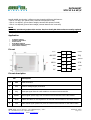
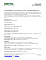
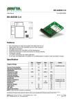
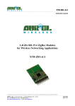
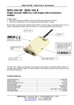
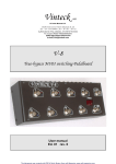
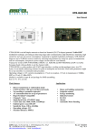
DATASHEET
XTR VF 2.4 HP/V
---------------------------------------------------------------------------------------------------------------------------------------------------
XTR VF 2.4 HP/V
Very Fast Low Power Multichannel Transceiver equipped with power amplifier
Picture has been made from a sample. The real shape could change based on latest release.
DESCRIPTION
Long range transceiver XTR VF 2.4 HP/V is pin-to-pin compatible with previous models
• XTR VF 2.4 LP
• XTR VF 2.4 PA-LNA
representing an extension suitable to reach a RF output power (ERP) increate up to 18dBm (compared with
the 4 dBm of the XTR VF 2.4 LP). In this way it’s possible to cover in open space outdoor conditions, a radio
link of 200 meters.
In case the final application needs to use a battery powered device, and a very low power steady
consumption, two version (XTR VF 2.4 LP and XTR VF 2.4 HP/V) are fully compatible simply by providing
some additions to the SW (see dedicated paragraph).
It operates in the License Free Industrial, Scientific and Medical (ISM) band at 2.4GHz and it offers a
complete radio module solution for integration into existing or new 2.4GHz products. It uses a DSSS (Direct
Sequence Spread Spectrum) technique that allows operation in disturbed environments and that reduces the
interference caused by traditional narrowband signals. This technique also allows coexistence with Bluetooth
and Wi-Fi as well as all other wireless technologies that utilize the 2.4GHz ISM Band.
Transceiver embeds a front-end power amplifier for transmission, and a Low Noise Amplifier to clear up the
signal received. Module can be connected to a micro controller and one or more external devices via SPI
Interface. This last facility makes possible full transceiver programmability: in particular, possibility is given
to set RF channel, data transmission speed and RF radiated power level.
Thanks to the power amplifier, output power could achieve 18 dBm (step from -10 to +18dBm). RF channels
available are 76 and Transmission range is selectable from 16Kbit/sec to 250Kbit/sec according to the used
spreading code. It can be increased to 1Mbit/sec if spread spectrum technique is not used.
Technical features are subject to change without notice. AUR°EL S.p.A does not assume responsibilities for any damage caused by the device’s misuse..
--------------------------------------------------------------------------------------------------------------------------------------------------------------------AUREL S.p.A. Via Foro dei Tigli, 4 - 47015 Modigliana (FC) – ITALY
18/06/2014 - Rev.B
Pag 1 di 4
Tel.: +39.0546.941124 Fax: +39.0546.941660
http://www.aurelwireless.com - email: [email protected]
DATASHEET
XTR VF 2.4 HP/V
---------------------------------------------------------------------------------------------------------------------------------------------------
Actually AUREL has develop 3 different versions based on different HW features:
- XTR VF 2.4 HP/V, (90° pinout frame, Antenna PIFA printed on PCB)
- XTR VF 2.4 HP/H-AI (pinout frame straight, Antenna PIFA printed on PCB)
- XTR VF 2.4 HP/H-AE (pinout frame straight, esternal Antenna ULF conncetor)
NOTE:
Since MAY 2014 Aurel produce this version. Previous family PA-LNA version are totally replaced
in term of pinout, overall dimension, technical features, performances, and user command.
Application
Irrigation Systems
Industrial Automation
Access control
Road Works Lighting
Long Distance Data Collection
Environment Telemetry
Pin out
VCC
2
1
GND
nRESET
4
3
IRQ
nSS
6
5
MOSI
MISO
8
7
SCK
NC
10
9
GND
NC
12
11
NC
Pin out description
Pin
Description
1,9
GND
GND connection
2
VCC
Positive Voltage supply connection
3
IRQ
Interrupt signal from the radio module to an external microcontroller
4
nRESET
5
MOSI
Master Out Slave In. SPI signal from an external microcontroller to the radio module.
6
nSS
Slave Select signal (active low) from an external microcontroller to the radio module
Reset signal (active high) from an external microcontroller to the radio module
Technical features are subject to change without notice. AUR°EL S.p.A does not assume responsibilities for any damage caused by the device’s misuse..
--------------------------------------------------------------------------------------------------------------------------------------------------------------------AUREL S.p.A. Via Foro dei Tigli, 4 - 47015 Modigliana (FC) – ITALY
18/06/2014 - Rev.B
Pag 2 di 4
Tel.: +39.0546.941124 Fax: +39.0546.941660
http://www.aurelwireless.com - email: [email protected]
DATASHEET
XTR VF 2.4 HP/V
---------------------------------------------------------------------------------------------------------------------------------------------------
7
SCK
8
MISO
SPI clock from an external microcontroller to the radio module
Master In Slave Out. SPI signal from the radio module to an external microcontroller
Technical specifications
Features
Min
Voltage Supply
2.0
Current supply (RX mode)
Current supply (Tx mode step 6)
Tip
Max
Unit
3.6
V
31
100
Current supply (Tx mode step 4)
Current supply (Standby mode)
2
Modulation type
GFSK
Receiver sensitivity @250kbit/s
-100
mA
130
mA
80
mA
uA
dBm
RF power out (ERP) (1)(2)
-10
18
dBm
RF channels frequencies
2404
2480
MHz
RF bandwith
Operating temperature
1
0
MHz
+70
°C
(1) Posted values point out an E.R.P. power for version with the PIFA integrated antenna, and power
available on the antenna connector UFL in case of version with external antenna.
(2) To be in compliance with the EUROPEAN standard requirements, max. output power level is 10mW
(reference rule EN 300 328). This condition is satisfied with step n°4 of 0x03 register. Using step n°6 of
that register, will obtained the max output power +18dBm. Please note to don’t use the step n°7
Reference Rules and reference documentation
XTR VF 2.4 HP/V modules fully satisfies the European legislations EN 300-328 and EN 301-489 with max.
power supply of 3.6V. Products are tested following the directive EN 60950 and it can be used inside a
dedicated insulated containers, assuring the harmony with the above standards. Module must be powered
by a very low Voltage source, protected against the short circuits.
If Modules are incorporated into a product the Users must ensure the antenna insulation, due output RF
transmitter can’t support directly the static charges foreseen by the EN 61000-4-2 standards.Modules can be
installed inside containers that assuring the surpassing of EN 61000 standards, are not directly applicable
to it.
For information on technical details of XTR VF 2.4 LP such as register settings, timing, application interfaces,
clocking and power managing, refer to the data sheet of the CYRF6936 Radio SoC on Cypress internet site:
www.cypress.com.
Technical features are subject to change without notice. AUR°EL S.p.A does not assume responsibilities for any damage caused by the device’s misuse..
--------------------------------------------------------------------------------------------------------------------------------------------------------------------AUREL S.p.A. Via Foro dei Tigli, 4 - 47015 Modigliana (FC) – ITALY
18/06/2014 - Rev.B
Pag 3 di 4
Tel.: +39.0546.941124 Fax: +39.0546.941660
http://www.aurelwireless.com - email: [email protected]
DATASHEET
XTR VF 2.4 HP/V
---------------------------------------------------------------------------------------------------------------------------------------------------
Firmware additions compared with the previous module Aurel XTR VF 2.4 LP
XTR VF 2.4 HP/V, compared to the previous mododule XTR VF 2.4 LP, introducea power amplifier (PA) and a
Low Noise Amplifier (LNA). These additional components are managed inside the module itself through the
lines PACTL/GPIO (pin 30) e XOUT/GPIO (pin 29) of the CYRF6936.
Therefore, it’s necessary to programm the CYRF6936 to use these lines as GPIO and drive them properly.
At device inizialization time, it’s necessary to setup XOUT and PACTL as GPIO and setup as low output as
follow:
setting XOUT as GPI0:
Register 0x0C => Bit 6 = Bit 7 = 1
setting PACTL as GPIO:
Register 0x0D => Bit 2 = 1
setting XOUT and PACTL as standard CMOS Output
Register 0x0D => Bit 3 = Bit 4 = 0
Output setting XOUT and PACTL to value 0:
Register 0x0E => Bit 5 = Bit 7 = 0
XOUT and PACTL management is different depending if device is in transmission, in reception or in power
down, as follow:
Transmission
Before to activate the transmission, it’s necessary to switch on the Power amplifier
Therefore before to lift up TX GO bit on register 0x02, it’s necessary perform the following operation:
Register 0x0E => Bit 5 = Bit 7 = 1 meaning PACTL and XOUT = 1
Reception
Before to activate the reception, it’s necessary to switch on the Low Noise Amplifier
Therefore before to lift up RX GO bit on register 0x05, it’s necessary perform the following operation:
Register 0x0E => Bit 5 = 0 , Bit 7 = 1 meaning PACTL = 0 and XOUT = 1
Power Down
In order to obtain a low concumption, it’s necessary disable both PA and LNA. Therefore before to put the
device in power down or Idle mode, it’s necessary perform the following operation:
Register 0x0E => Bit 5 = Bit 7 = 0 meaning PACTL = XOUT = 0
Technical features are subject to change without notice. AUR°EL S.p.A does not assume responsibilities for any damage caused by the device’s misuse..
--------------------------------------------------------------------------------------------------------------------------------------------------------------------AUREL S.p.A. Via Foro dei Tigli, 4 - 47015 Modigliana (FC) – ITALY
18/06/2014 - Rev.B
Pag 4 di 4
Tel.: +39.0546.941124 Fax: +39.0546.941660
http://www.aurelwireless.com - email: [email protected]