1
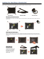
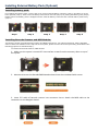
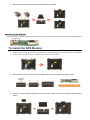
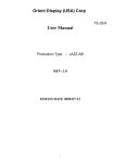
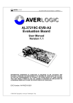
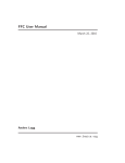
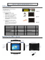
PM-511 Quick Setup Guide v1.0
Getting Started
1. Switch ON the main battery(Figure 1)
a. Main battery switch is located on rear side of
yellow label battery door
b. Adjust DIP switch to “ON”
Figure 1
c. Place the battery door back
2.
a.
b.
c.
3.
Plugging the Power Cable
(Figure 2)
Plug the AC power cord into the power
socket of the AC power adapter.
Plug the other end of the AC power
cord to a live AC wall outlet.
Plug the connector of the AC adapter
to the DC-IN port found at the left side
of the PM-521.
Figure 2
Turning on the PM-521 System
(Figure 3)
To turn on the PM-521 System, press
the power button. The power LED will
light up to indicate that the PM-521
System is on.
Main Packing List
Figure 3
QTY
QTY
QTY
Main system
1
Stylus
1
Hand Screws
4
Power Adapter
1
Hand Strap
1
Corner Rubber Screw
4
Corner Rubber
2
Shoulder Strap
1
Ethernet Cable
1
Accessories (Option)
QTY
QTY
QTY
Barcode Scanner
1
MSR
1
DeskTop Docking
1
Vehicle Docking
1
GPS
1
Vehicle Power Adapter
1
Battery Charger
1
Carrying Bag
1
Handle Secures
1
External Battery Pack
1
Exploring Your PM-511 System
Installing Your Hand Strap or Shoulder Belt
Tablet provides you an optional detachable hand strap and shoulder belt. You can use the hand strap or shoulder
belt to carry the Tablet securely and safely when you are outside your home or office.
Hand Strap
Shoulder Belt
Hand Screws
Placing by the hand screws:
To attach the hand strap and shoulder belt to carry the Tablet , please place the four hand screws as
shown below.
Attaching the hand strap:
Attach the hand strap to the rear of your Tablet with sticking the hooks both on the hand strap and
Tablet . Ensure the hand strap is securely attached. The hand strap makes it easy to carry the device on
one hand.
Attaching the
shoulder belt:
To attach the shoulder belt
to the rear of your tablet
PC, please hook shoulder
belt with the two hook
screws on the Tablet as
shown right.
Installing External Battery Pack (Optional)
Installing battery pack:
For installing the battery pack, remove the cover of the external battery connector (step 1) and place it on the
lower position (step 2). Then screw the battery frame at the rear side (step 3) for placing the battery pack (step 4).
Please assure the battery pack is snapped into the external battery connector and external battery hook firmly
(step 5).
Step1
Step 2
Step 3
Step 4
Step 5
Installing Barcode Scanner and MSR Module:
The PM-521 System provides barcode scanner and MSR functions for your optional selection, before installing
either of these two modules on the top side of the system, please remove the screws previously (illustrated in the
following graphics as indicated step 1).
To install the Barcode Scanner /MSR Module:
1. Make sure the system is turned off. Unscrew four screws from the accessory door on top of
the system.
2. Mount and secure the Barcode/MSR daughter board into the mainboard with screws.
3. Insert FFC cable of barcode scanner into connector slot or Attach the MSR cable to the
connectors on the daughter board.
4. Screw to secure the Barcode Scanner/MSR onto the tablet.
Installing GPS Module:
Before installing the GPS module, please adjust to DIP 2-3 for GPS mode as indicated in the following diagram.
To install the GPS Module:
1. Make sure the system is turned off, internal battery detect DIP switch set to off and unplug AC adapter.
2. Unscrew four screws from the accessory door on top of the system.
3. Mount and secure the GPS Tracker daughter board into the mainboard with screws.
4. Insert FFC cable of GPS module into connector slot. Screw to secure the GPS module onto the
tablet.