1
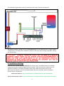
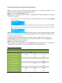
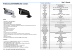
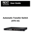
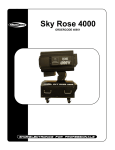
SolarImmersion IV Quick Installation Guide 1.2 1. Safety Notes Potentially dangerous High voltages are present and therefore this equipment should only be installed by a qualified person. Connect the equipment according to current IEE regulations and separate all Wiring according to IEC1010. Make sure all screw terminals are tight before you switch the equipment ON. Don’t touch any circuitry after you have connected the equipment, because there may be lethal voltages on the circuit board or connector terminals Equipment designed for Pollution-Degree 2 environments only. This means you must install it in a clean, dry environment. 2. Parts List 1 x SOLARIMMERSION IV: 1 x Clip on sensor: Cable length= 1 meter Weight = 650g 3. Dimensions 200mm 150mm Mounting Fixing holes 175mm 1 65mm 4. Location To keep the installation quick and easy, we recommend that SOLARIMMERSION IV is installed near to the consumer unit as most of the connections required can usually be found here. When choosing a suitable place to install SOLARIMMERSION IV, the following should be considered: Near to the main incoming mains supply of the property Access to the immersion heater supply cable (normally at the consumer unit) Access to suitable supply via 16A MCB or 13A fused outlet Ease of access and visibility of SOLARIMMERSION IV LCD Screen and control buttons Good ventilation to keep air flowing through the unit – at least 100mm around the unit. Suitable cable access point location – through the top or bottom of the unit. Secure the SOLARIMMERSION IV to the wall with the three screws or using suitable fixings for the surface type. 5. Wiring Sensor Clip Installation The correct installation and positioning of the current sensor clip is very important for the efficient operation of SOLARIMMERSION IV. Wrongly installing the sensor clip could result in importing of power and the user incurring additional costs for electricity. The sensor clip should be installed at the main incoming grid supply to the building which could be from the utility/electricity meter. (Please note - it is Utility/Electricity meter NOT the PV generation meter). Close the clip around the Live or Neutral cable from the utility/electricity meter. Please ensure the sensor clip is positioned nearest to the utility/electricity meter as possible. (Only open a consumer unit if you are qualified to do so or are an experienced electrician). If there is more than one consumer unit, the clip must be positioned at the primary income source – before it splits. Connect the clamp wire to the terminals inside SOLARIMMERSION IV. If the sensor clip cable is not long enough it can be extended up to 50m but this must be done using a double twisted pair cable in order to stop any possible interference and a firm connection to the original cable is required. Try to keep the extension cable as short as possible, as the signal strength from the sensor is very low. 2 For standard single heater control, no wiring to the relay terminal are required. N The default factory settings of the SOLARIMMERSION IV are optimised for a single heater configuration. This keeps the installation simple, as the only menu setting required is setting the correct time. 6. Installation Settings Once the unit is wired, SOLARIMMERSION IV can be setup. The default values are already setup to work with standard single immersion heater. Only the clock will need to set. For advance installation including; secondary load, relay mode, de-strat etc refer to the Advanced User Manual, this can be downloaded from the link below. Also find Support System link for any queries. Advanced User Manual - http://solarimmersion.co.uk/solarimmersion-support/downloads/ Online Technical Support System - http://solarimmersion.co.uk/solarimmersion-support/technical-support/ 3 Follow the steps below to calibrate and setup the unit. Step 1: Turn off the PV or micro generation system. This is to make sure power is only imported, which is essential for sensor clip calibration. Step 2: Turn on SOLARIMMERSION IV unit. Step 3: Turn on a high load like a kettle or a 2kW heater to make sure power is imported and wait for 5 seconds. 3a: If the sensor clip is installed correctly, the display will be as below with the ASTERISK symbol ( ) Blinking. 3b: If the display is as below, then you have to swap the wiring on the CT sensor terminals. Once the terminals are swapped, restart the switch and make sure the display is as picture 3a. Step 4: Set the correct time. Press ENT to change the hour and use Up/Down buttons. When correct hour is selected to save the settings press ENT. The new value will be saved and you will return to the home screen. To set the minute, repeat the step above until you come to “Menu>Hour” scroll up to change minute, press enter and select correct minutes using the “UP” and “DOWN” keys. Press “ENT” button to save the minutes. Step 5: Turn the PV inverter back on. That completes the installation and SOLARIMMERSION IV should now start to divert any surplus power if available to the immersion heater or the connected load. Electrical Specifications Description Min Nominal Max Supply Voltage (VAC) 220 240 260 Supply Frequency (Hz) 45Hz 50Hz 55Hz Load Current (A) 13 16 Load Size (kW) 3 4 Relay Contact Voltage 250Vac Relay Contact Current 13A Clamp Current 16A 100A PV System Size 500W 4000W No Max Operating Temperature -5˚C 20˚C 40˚C 4