1
Adafruit PN532 RFID/NFC Breakout and Shield
Created by lady ada
Last updated on 2015-07-30 12:20:13 PM EDT
Guide Contents
Guide Contents
Overview
Breakout Wiring
2
5
6
Wiring the Breakout for SPI
Shield Wiring
11
Solder the Headers
Using the Adafruit NFC Shield with I2C
Using with the Arduino Leonardo and Yun
Arduino Library
Which Library?
Library Installation
Testing MiFare
11
12
13
15
15
15
16
About NFC
18
NFC (Near Field Communication)
Passive Communication: ISO14443A Cards (Mifare, etc.)
Active Communication (Peer-to-Peer)
NFC Data Exchange Format (NDEF)
Reading
MiFare Cards & Tags
MiFare Classic Cards
EEPROM Memory
4 Block Sectors
16 Block Sectors
Accessing EEPROM Memory
Note on Authentication
Example of a New Mifare Classic 1K Card
MiFare Ultralight Cards
EEPROM Memory
Lock Bytes (Page 2)
OTP Bytes (Page 3)
Data Pages (Page 4-15)
Accessing Data Blocks
Read/Write Lengths
About the NDEF Format
NDEF (NFC Data Exchange Format)
© Adafruit Industries
6
https://learn.adafruit.com/adafruit-pn532-rfid-nfc
18
18
18
19
19
21
21
21
21
23
23
23
24
26
26
27
27
27
28
28
29
29
Page 2 of 53
NDEF Messages
NDEF Records
Record Header (Byte 0)
Type Length
Payload Length
ID Length
Record Type
Record ID
Payload
Well-Known Records (TNF Record Type 0x01)
URI Records (0x55/'U')
Test Records
Smart Poster Records
Example NDEF Records
Using Mifare Classic Cards as an NDEF Tag
Mifare Application Directory (MAD)
Mifare Application Directory 1 (MAD1)
Mifare Application Directory 2 (MAD2)
MAD Sector Access
Storing NDEF Messages in Mifare Sectors
TLV Blocks
Memory Dump of a Mifare Classic 1K Card with an NDEF Record
NDEF Records
Using with LibNFC
29
29
30
32
32
32
32
32
32
32
32
34
35
35
35
36
36
36
36
37
37
38
40
43
Using the PN532 Breakout Boards with libnfc
libnfc In Linux (Ubuntu 10.10 used in this example)
Step One: Download libnfc
Step Two: Configure libnfc for PN532 and UART
Step Three: Build and install libnfc
Step Four: Check for installed devices
Step Five: Poll for an ISO14443A (Mifare, etc.) Card
libnfc With Mac OSX Lion
43
43
43
43
44
44
45
45
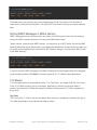
Download and build libnfc and configure if for PN532 UART (making the code changes
above before running make):
46
If everything worked out, switch to the examples folder and see if you can find the
PN532 and wait for an appropriate tag:
46
FAQ
Downloads
© Adafruit Industries
47
52
https://learn.adafruit.com/adafruit-pn532-rfid-nfc
Page 3 of 53
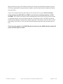
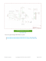
Version 1.6 schematic
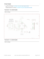
Version 1.3 schematic
© Adafruit Industries
https://learn.adafruit.com/adafruit-pn532-rfid-nfc
52
52
Page 4 of 53
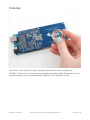
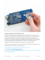
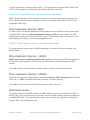
Overview
Hey! So this is not a full tutorial, its just a quickstart guide while we do more research into
RFID/NFC. There's a lot of info here but not everything is explained in detail. We hope to fill out the
tutorial but there's not a lot of good information about NFC so it's taking a bit of time!
© Adafruit Industries
https://learn.adafruit.com/adafruit-pn532-rfid-nfc
Page 5 of 53
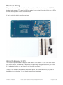
Breakout Wiring
This part of the tutorial is specifically for the Breakout board. We show how to use it with SPI. The
breakout also supports TTL serial and I2C but we don't have a tutorial for using it that way as SPI is
the most cross-platform method to communicate
If you're using the shield, check the next page
Wiring the Breakout for SPI
The PN532 chip and breakout is designed to be used by 3.3V systems. To use it with a 5V system
such as an Arduino, a level shifter is required to convert the high voltages into 3.3V. If you have a
3.3V embedded system you won't have to use the shifter of course!
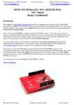
To begin, we'll solder in the header to the breakout board. You'll need two small 3-pin pieces of
header and one 8-pin piece. You can break these off of a large piece.
© Adafruit Industries
https://learn.adafruit.com/adafruit-pn532-rfid-nfc
Page 6 of 53
© Adafruit Industries
https://learn.adafruit.com/adafruit-pn532-rfid-nfc
Page 7 of 53
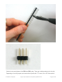
Solder the two small pieces to the SEL0 and SEL1 pads. These are interface selectors for the chip.
Depending on how the jumpers are inserted the chip will talk in TTL serial, i2c or SPI. Also solder a
© Adafruit Industries
https://learn.adafruit.com/adafruit-pn532-rfid-nfc
Page 8 of 53
strip to the end so you can plug it into a breadboard.
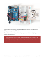
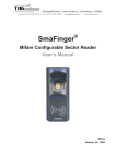
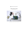
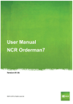
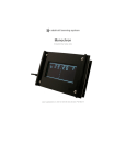
Wire up the 4050 level shifter chip to the Arduino as shown. The notch in the 4050 is at the 'top' in
this image.
Arduino digital pin 2 is connected to 4050 pin 9 (orange wire)
Arduino digital pin 3 is connected to 4050 pin 11(yellow wire)
Arduino digital pin 4 is connected to 4050 pin 14 (green wire)
On the breakout board
3.3Vin is connected to the Arduino 3.3V pn
SCK is connected to 4050 pin 10 (orange wire)
MISO is connected to Arduino pin 5 (blue wire)
MOSI is connected to 4050 pin 12 (yellow wire)
SSEL is connected to 4050 pin 15& (green wire)
GND connects to Arduino ground (black wire)
Also connect 4050 pin #1 to 3.3V and pin #8 to ground.
Click to see a larger image. The red power wire should be connected to the 3.3v pin on the Arduino!
© Adafruit Industries
https://learn.adafruit.com/adafruit-pn532-rfid-nfc
Page 9 of 53
Also, we need to select SPI as the interface so on SEL1 place the jumper in the ON position. for
SEL0 place the jumper in the OFF position.
That's it! Later on you can change what Arduino pins you are using but for the beginning test we
suggest matching our wiring.
If you are using the shield in I2C mode, you will also need to add two 1.5K pullups on the
SCL/SDA lines, since the breakout and the Arduino don't include the pullups. Simply solder or
add a 1.5K resistor between SCL and 3.3V, and SDA and 3.3V, and then connect the
breakout as you normally would.
© Adafruit Industries
https://learn.adafruit.com/adafruit-pn532-rfid-nfc
Page 10 of 53
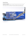
Shield Wiring
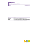
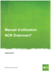
Solder the Headers
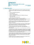
The first step is to solder the headers to the shield. Cut the header strip to length and insert the
sections (long pins down) into an Arduino. Then place the shield on top and solder each pin.
© Adafruit Industries
https://learn.adafruit.com/adafruit-pn532-rfid-nfc
Page 11 of 53
Using the Adafruit NFC Shield with I2C
The Adafruit NFC shield is designed to be used using the I2C by default. I2C only uses two pins
(Analog 4 and 5 which are fixed in hardware and cannot be changed) to communicate and one pin
as an 'interrupt' pin (Digital 2 - can be changed however). What is nice about I2C is that it is a
'shared' bus - unlike SPI and TTL serial - so you can put as many sensors as you'd like all on the
same two pins, as long as their addresses don't collide/conflict. The Interrupt pin is handy because
instead of constantly asking the NFC shield "is there a card in view yet? what about now?"
constantly, the chip will alert us when a NFC target comes into the antenna range.
The shield is drop-in compatible with any Classic Arduino (UNO, Duemilanove, Diecimilla, etc using
the ATmega168 or '328) as well as any Mega R3 or later.
Mega R2 Arduinos work as well but you need to solder a wire from the
(http://adafru.it/aUS)SDA (http://adafru.it/aUS)
and (http://adafru.it/aUS)SCL (http://adafru.it/aUS) pin holes to the Mega's I2C pins on Digital #20
and #21 (http://adafru.it/aUS)
© Adafruit Industries
https://learn.adafruit.com/adafruit-pn532-rfid-nfc
Page 12 of 53
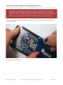
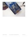
Using with the Arduino Leonardo and Yun
The IRQ pin is tied to Digital pin #2 by default. However, on the Arduino Leonardo and Yun,
digital #2 is used for I2C which will not work. If using with a Leonardo or Yun, cut the trace
beween the IRQ pin and Digital #2 and solder a wire from IRQ pin to Digital #4 or higher. Then
change the example code so the the IRQ pin is declared as the new pin (say #6) not #2
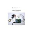
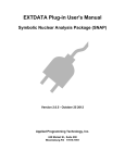
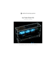
Here are some photos of setting the IRQ pin to digital 6. First, use a sharp hobby knife to cut the
trace from IRQ to 2
Solder a wire from IRQ to #6
© Adafruit Industries
https://learn.adafruit.com/adafruit-pn532-rfid-nfc
Page 13 of 53
© Adafruit Industries
https://learn.adafruit.com/adafruit-pn532-rfid-nfc
Page 14 of 53
Arduino Library
Which Library?
In the past there were two separate Arduino libraries for using the Adafruit NFC boards. One library
supported the breakout over a SPI connection, and the other library supported the breakout or
shield over an I2C connection. However both of these libraries have been merged into a single
Arduino library, Adafruit-PN532 (http://adafru.it/eHi).
The Adafruit PN532 library has the ability to read MiFare cards, including the hard-coded ID
numbers, as well as authenticate and read/write EEPROM chunks. It can work with both the
breakout and shield using either a SPI or I2C connection.
Library Installation
Download the Adafruit PN532 library from github (http://adafru.it/aSX). Uncompress the folder and
rename the folder Adafruit_PN532. Inside the folder you should see the Adafruit_PN532.cpp and
Adafruit_PN532.h files. Install the Adafruit_PN532 library foler by placing it in your
arduinosketchfolder/libraries folder. You may have to create the libraries subfolder if this is your
first library. You can read more about installing libraries in our tutorial (http://adafru.it/aYG).
Restart the Arduino IDE. You should now be able to select File > Examples > Adafruit_PN532 >
readMifare sketch.
If you're using the NFC breakout with a SPI connection that uses the wiring shown on previous
pages you can immediately upload the sketch to the Arduino and skip down to the Testing
MiFare (http://adafru.it/eHj) section.
If you're using the NFC shield, or are using the breakout with an I2C connection then you
must make a small change to configure the example for I2C. Scroll down to these lines near the top
of the sketch:
© Adafruit Industries
https://learn.adafruit.com/adafruit-pn532-rfid-nfc
Page 15 of 53
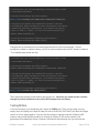
// Uncomment just _one_ line below depending on how your breakout or shield
// is connected to the Arduino:
// Use this line for a breakout with a SPI connection:
Adafruit_PN532 nfc(PN532_SCK, PN532_MISO, PN532_MOSI, PN532_SS);
// Use this line for a breakout with a hardware SPI connection. Note that
// the PN532 SCK, MOSI, and MISO pins need to be connected to the Arduino's
// hardware SPI SCK, MOSI, and MISO pins. On an Arduino Uno these are
// SCK = 13, MOSI = 11, MISO = 12. The SS line can be any digital IO pin.
//Adafruit_PN532 nfc(PN532_SS);
// Or use this line for a breakout or shield with an I2C connection:
//Adafruit_PN532 nfc(PN532_IRQ, PN532_RESET);
Change them so the second line is uncommented and the first line is commented. This will
configure the sketch to make the library use I2C for communication with the NFC shield or breakout.
The modified code should look like:
// Uncomment just _one_ line below depending on how your breakout or shield
// is connected to the Arduino:
// Use this line for a breakout with a SPI connection:
//Adafruit_PN532 nfc(PN532_SCK, PN532_MISO, PN532_MOSI, PN532_SS);
// Use this line for a breakout with a hardware SPI connection. Note that
// the PN532 SCK, MOSI, and MISO pins need to be connected to the Arduino's
// hardware SPI SCK, MOSI, and MISO pins. On an Arduino Uno these are
// SCK = 13, MOSI = 11, MISO = 12. The SS line can be any digital IO pin.
//Adafruit_PN532 nfc(PN532_SS);
// Or use this line for a breakout or shield with an I2C connection:
Adafruit_PN532 nfc(PN532_IRQ, PN532_RESET);
Then upload the example to the Arduino and continue on. Note that you need to make a similar
change to pick the interface for any other NFC example from the library.
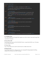
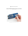
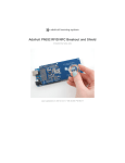
Testing MiFare
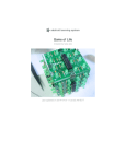
In the serial monitor, you should see that it found the PN532 chip. Then you can place your tag
nearby and it will display the 4 byte ID code (this one is 0xAE 0x4C 0xF0 0x6C) and then the integer
version of all four bytes together. You can use this number to identify each card. Recently NXP
made so many cards that they actually ran through all 4 Bytes (2^32) so the number is not
guaranteed to be absolutely unique. However, the chances are extremely slim you will have two
© Adafruit Industries
https://learn.adafruit.com/adafruit-pn532-rfid-nfc
Page 16 of 53
cards with the same ID so as long as you aren't using these cards for anything terribly important
(like money transfer) its fine to use the number as a unique identifier
© Adafruit Industries
https://learn.adafruit.com/adafruit-pn532-rfid-nfc
Page 17 of 53
About NFC
NFC (Near Field Communication)
NFC (Near Field Communication) is a set of short-range (typically up to 10cm) wireless
communication technologies designed to offer light-weight and secure communication between two
devices. While NFC was invented by NXP (Phillips at the time), Nokia and Sony, the main body
behind the NFC 'standard' today is the NFC Forum (http://adafru.it/aSy), who are responsible for
publishing and maintaining a variety of standards relating to NFC technology.
NFC operates at 13.56MHz, and is based around an "initiator" and "target" model where the initiator
generates a small magnetic field that powers the target, meaning that the target does not require a
power source. This means of communication is referred to as Passive Communication, and is
used to read and write to small, inexpensive 13.56MHz RFID tags based on standards like
ISO14443A. Active communication (peer-to-peer) is also possible when both devices are
powered, where each device alternately creates its own magentic field, with the secondary device
as a target and vice versa in continuous rotation.
Passive Communication: ISO14443A Cards (Mifare, etc.)
While the PN53x family of transceivers from NXP are compatible with a number of 13.56MHz RFID
card standards, by far the most popular standard is ISO14443A. A variety of manufacturers produce
ISO14443A compatible cards or chips, but the most common are based around the Mifare family
from NXP. Mifare Classic and Mifare Ultralight are probably the most frequently encountered and
useful for basic projects, though many tags with improved security and encryption also exist (Mifare
DESFire, etc.). All of the tags sold at adafruit.com are Mifare Classic 1K, meaning that they contains
1K (1024 bytes) of programmable EEPROM memory which can be read and modified in passive
mode by the initiator device (the PN532).
While all ISO14443A cards share certain common characteristics on the highest level (defined by
the four part standard), each set of Mifare chips (Classic, Ultralight, Plus, DESFire, etc.) has it's own
features and peculiarities. The two most common formats are described below.
Mifare Classic (http://adafru.it/cl7): These cards are extremely common, and contain 1K or 4K
of EEPROM, with basic security for each 64 byte (1K/4K cards) or 256 byte (4K cards) sector.
Mifare Ultralight (http://adafru.it/cl7): Contains 512 bytes of EEPROM, including 32-bits of
OTP memory. These tags are inexpensive, often come in sticker format and are are
frequently used for transportation ticketing, concert tickets, etc.
Active Communication (Peer-to-Peer)
Active or "Peer-to-Peer" communication is still based around the Initiator/Target model described
earlier, but both devices are actively powered and switch roles from being an Initiator or a Target
during the communication. When one device is initiating a conversation with the other, it enables it's
magnetic field and the receiving device listens in (with it's own magnetic field disabled). Afterwards,
© Adafruit Industries
https://learn.adafruit.com/adafruit-pn532-rfid-nfc
Page 18 of 53
the target/recipient device may need to respond and will in turn activate it's own magnetic field and
the original device will be configured as the target. Despite two devices being present, only one
magnetic field is active at a time, with each device constantly enabling or disabling its own magnetic
field.
ToDo: Add better description of active mode, but I need to test it out a bit first myself!
NFC Data Exchange Format (NDEF)
The NFC Data Exchange Format (NDEF) is a standardised data format that can be used to
exchange information between any compatible NFC device and another NFC device or tag. The
data format consists of NDEF Messages and NDEF Records. The standard is maintained by the
NFC Forum and is freely available for consultation but requires accepting a license agreement to
download (http://adafru.it/aSA).
The NDEF format is used to store and exchange information like URIs, plain text, etc., using a
commonly understood format. NFC tags like Mifare Classic cards can be configured as NDEF tags,
and data written to them by one NFC device (NDEF Records) can be understood and accessed by
any other NDEF compatible device. NDEF messages can also be used to exchange data between
two active NFC devices in "peer-to-peer" mode. By adhering to the NDEF data exchange format
during communication, devices that would otherwise have no meaningful knowledge of each other
or common language are able to share data in an organised, mutually understandable manner.
The NDEF standard includes numerous Record Type Definitions (RTDs) that define how
information like URIs should be stored, and each NDEF device, tag or message can contained
multiple RTDs. Standard RTD definitions are described in "NFC Record Type Definition (RTD)
Specification” maintained by the NFC Forum.
* NDEF Overview (http://adafru.it/cl7): This page offers a more detailed explanation of NDEF,
including how Mifare Classic cards can be used to store NDEF messages.
NOTE: The dedicated NDEF page is still a work in progress and some information is currently
incomplete.
Reading
For more details about NFC/RFID and this chip we suggest the following fantastic resources:
RFID selection guide (http://adafru.it/aSC) - a lot of details about RFID in general
Nokia's Introduction to NFC (http://adafru.it/aSD)- a lot of details about NFC in general
NXP S50 chip datasheet (http://adafru.it/aSE) , the chip inside MiFare classic tags
NXP PN532 Short Form Datasheet (http://adafru.it/aSF)
NXP PN532 Long Form Datasheet (http://adafru.it/aSG)
NXP PN532 User Manual (http://adafru.it/aSH)
NXP PN532 App Note (http://adafru.it/aSI)
© Adafruit Industries
https://learn.adafruit.com/adafruit-pn532-rfid-nfc
Page 19 of 53
Using PN532 with libnfc (http://adafru.it/aSJ)
NFC Glossary (http://adafru.it/aSK)
© Adafruit Industries
https://learn.adafruit.com/adafruit-pn532-rfid-nfc
Page 20 of 53
MiFare Cards & Tags
MiFare is one of the four 13.56MHz card 'protocols' (FeliCa is another well known one) All of the
cards and tags sold at the Adafruit shop use the inexpensive and popular MiFare Classic chipset
MiFare Classic Cards
MIFARE Classic cards come in 1K and 4K varieties. While several varieties of chips exist, the two
main chipsets used are described in the following publicly accessible documents:
MF1S503x Mifare Classic 1K data sheet (http://adafru.it/aSL)
MF1S70yyX MIFARE Classic 4K data sheet (http://adafru.it/aSM)
Mifare Classic cards typically have a 4-byte NUID that uniquely (within the numeric limits of the
value) identifies the card. It's possible to have a 7 byte IDs as well, but the 4 byte models are far
more common for Mifare Classic.
EEPROM Memory
Mifare Classic cards have either 1K or 4K of EEPROM memory. Each memory block can be
configured with different access conditions, with two seperate authentication keys present in each
block.
Mifare Classic cards are divided into section called sectors and blocks. Each "sector" has
individual access rights, and contains a fixed number of "blocks" that are controlled by these access
rights. Each block contains 16 bytes, and sectors contains either 4 blocks (1K/4K cards) for a total of
64 bytes per sector, or 16 blocks (4K cards only) for a total of 256 bytes per sector. The card types
are organised as follows:
1K Cards - 16 sectors of 4 blocks each (sectors 0..15)
4K Cards - 32 sectors of 4 blocks each (sectors 0..31) and 8 sectors of 16 blocks each
(sectors 32..39)
4 Block Sectors
1K and 4K cards both use 16 sectors of 4 blocks each, with the bottom 1K of memory on the 4K
cards being organised identically to the 1K models for compatability reasons. These individual 4
block sectors (containing 64 byts each) have basic security features are can each be configured
with seperate read/write access and two different 6-byte authentication keys (the keys can be
different for each sector). Due to these security features (which are stored in the last block, called
the Sector Trailer), only the bottom 3 blocks of each sector are actually available for data storage,
meaning you have 48 bytes per 64 byte sector available for your own use.
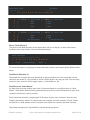
Each 4 block sector is organised as follows, with four rows of 16 bytes each for a total of 64-bytes
per sector. The first two sectors of any card are shown:
© Adafruit Industries
https://learn.adafruit.com/adafruit-pn532-rfid-nfc
Page 21 of 53
Sector Block Bytes
Description
------ ----- --------------0 1 2 3 4 5 6 7 8 9 10 11 12 13 14 15
1
3
2
1
0
[-------KEY A-------] [Access Bits] [-------KEY B-------] Sector Trailer
[
Data
] Data
[
Data
] Data
[
Data
] Data
0
3
2
1
0
[-------KEY A-------] [Access Bits] [-------KEY B-------] Sector Trailer
[
Data
] Data
[
Data
] Data
[
Manufacturer Data
] Manufacturer Block
Sector Trailer (Block 3)
The sector trailer block contains the two secret keys (Key A and Key B), as well as the access
conditions for the four blocks. It has the following structure:
Sector Trailer Bytes
-------------------------------------------------------------0 1 2 3 4 5 6 7 8 9 10 11 12 13 14 15
[
Key A
] [Access Bits] [
Key B
]
For more information in using Keys to access the clock contents, see Accessing Data Blocks further
below.
Data Blocks (Blocks 0..2)
Data blocks are 16 bytes wide and, depending on the permissions set in the access bits, can be
read from and written to. You are free to use the 16 data bytes in any way you wish. You can easily
store text input, store four 32-bit integer values, a 16 character uri, etc.
Data Blocks as "Value Blocks"
An alternative to storing random data in the 16 byte-wide blocks is to configure them as "Value
Blocks". Value blocks allow performing electronic purse functions (valid commands are: read, write,
increment, decrement, restore, transfer).
Each Value block contains a single signed 32-bit value, and this value is stored 3 times for data
integrity and security reasons. It is stored twice non-inverted, and once inverted. The last 4 bytes
are used for a 1-byte address, which is stored 4 times (twice non-inverted, and twice inverted).
Data blocks configured as "Value Blocks" have the following structure:
© Adafruit Industries
https://learn.adafruit.com/adafruit-pn532-rfid-nfc
Page 22 of 53
Value Block Bytes
-------------------------------------------------------------0 1 2 3 4 5 6 7 8 9 10 11 12 13 14 15
[ Value ] [ ~Value ] [ Value ] [A ~A A ~A]
Manufacturer Block (Sector 0, Block 0)
Sector 0 is special since it contains the Manufacturer Block. This block contains the manufacturer
data, and is read-only. It should be avoided unless you know what you are doing.
16 Block Sectors
16 block sectors are identical to 4 block sectors, but with more data blocks. The same structure
described in the 4 block sectors above applies.
Sector Block Bytes
Description
------ ----- -------------0 1 2 3 4 5 6 7 8 9 10 11 12 13 14 15
32
15
14
13
...
2
1
0
[-------KEY A-------] [Access Bits] [-------KEY B-------] Sector Trailer 32
[
Data
] Data
[
Data
] Data
[
[
[
Data
Data
Data
] Data
] Data
] Data
Accessing EEPROM Memory
To access the EEPROM on the cards, you need to perform the following steps:
1. You must retrieve the 4-byte NUID of the card (this can sometimes be 7-bytes long as well,
though rarely for Mifare Classic cards). This is required for the subsequent authentication
process.
2. You must authenticate the sector you wish to access according to the access rules defined in
the Sector Trailer block for that sector, by passing in the appropriate 6 byte Authentication
Key (ex. 0xFF 0xFF 0xFF 0xFF 0xFF 0xFF for new cards).
3. Once authenication has succeeded, and depending on the sector permissions, you can then
read/write/increment/decrement the contents of the specific block. Note that you need to reauthenticate for each sector that you access, since each sector can have it's own distinct
access keys and rights!
Note on Authentication
© Adafruit Industries
https://learn.adafruit.com/adafruit-pn532-rfid-nfc
Page 23 of 53
Before you can do access the sector's memory, you first need to "authenticate" according to the
security settings stored in the Sector Trailer. By default, any new card will generally be configured to
allow full access to every block in the sector using Key A and a value of 0xFF 0xFF 0xFF 0xFF
0xFF 0xFF. Some other common keys that you may wish to try if this doesn't work are:
0XFF 0XFF 0XFF 0XFF 0XFF 0XFF
0XD3 0XF7 0XD3 0XF7 0XD3 0XF7
0XA0 0XA1 0XA2 0XA3 0XA4 0XA5
0XB0 0XB1 0XB2 0XB3 0XB4 0XB5
0X4D 0X3A 0X99 0XC3 0X51 0XDD
0X1A 0X98 0X2C 0X7E 0X45 0X9A
0XAA 0XBB 0XCC 0XDD 0XEE 0XFF
0X00 0X00 0X00 0X00 0X00 0X00
0XAB 0XCD 0XEF 0X12 0X34 0X56
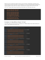
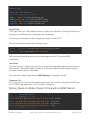
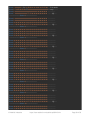
Example of a New Mifare Classic 1K Card
The follow memory dump illustrates the structure of a 1K Mifare Classic Card, where the data and
Sector Trailer blocks can be clearly seen:
[--------------------------Start of Memory Dump--------------------------]
------------------------Sector 0------------------------Block 0 8E 02 6F 66 85 08 04 00 62 63 64 65 66 67 68 69 ?.of?...bcdefghi
Block 1 00 00 00 00 00 00 00 00 00 00 00 00 00 00 00 00 ................
Block 2 00 00 00 00 00 00 00 00 00 00 00 00 00 00 00 00 ................
Block 3 00 00 00 00 00 00 FF 07 80 69 FF FF FF FF FF FF ......ÿ.?iÿÿÿÿÿÿ
------------------------Sector 1------------------------Block 4 00 00 00 00 00 00 00 00 00 00 00 00 00 00 00 00 ................
Block 5 00 00 00 00 00 00 00 00 00 00 00 00 00 00 00 00 ................
Block 6 00 00 00 00 00 00 00 00 00 00 00 00 00 00 00 00 ................
Block 7 00 00 00 00 00 00 FF 07 80 69 FF FF FF FF FF FF ......ÿ.?iÿÿÿÿÿÿ
------------------------Sector 2------------------------Block 8 00 00 00 00 00 00 00 00 00 00 00 00 00 00 00 00 ................
Block 9 00 00 00 00 00 00 00 00 00 00 00 00 00 00 00 00 ................
Block 10 00 00 00 00 00 00 00 00 00 00 00 00 00 00 00 00 ................
Block 11 00 00 00 00 00 00 FF 07 80 69 FF FF FF FF FF FF ......ÿ.?iÿÿÿÿÿÿ
------------------------Sector 3------------------------Block 12 00 00 00 00 00 00 00 00 00 00 00 00 00 00 00 00 ................
Block 13 00 00 00 00 00 00 00 00 00 00 00 00 00 00 00 00 ................
Block 14 00 00 00 00 00 00 00 00 00 00 00 00 00 00 00 00 ................
Block 15 00 00 00 00 00 00 FF 07 80 69 FF FF FF FF FF FF ......ÿ.?iÿÿÿÿÿÿ
------------------------Sector 4------------------------Block 16 00 00 00 00 00 00 00 00 00 00 00 00 00 00 00 00 ................
Block 17 00 00 00 00 00 00 00 00 00 00 00 00 00 00 00 00 ................
Block 18 00 00 00 00 00 00 00 00 00 00 00 00 00 00 00 00 ................
© Adafruit Industries
https://learn.adafruit.com/adafruit-pn532-rfid-nfc
Page 24 of 53
Block 18 00 00 00 00 00 00 00 00 00 00 00 00 00 00 00 00 ................
Block 19 00 00 00 00 00 00 FF 07 80 69 FF FF FF FF FF FF ......ÿ.?iÿÿÿÿÿÿ
------------------------Sector 5------------------------Block 20 00 00 00 00 00 00 00 00 00 00 00 00 00 00 00 00 ................
Block 21 00 00 00 00 00 00 00 00 00 00 00 00 00 00 00 00 ................
Block 22 00 00 00 00 00 00 00 00 00 00 00 00 00 00 00 00 ................
Block 23 00 00 00 00 00 00 FF 07 80 69 FF FF FF FF FF FF ......ÿ.?iÿÿÿÿÿÿ
------------------------Sector 6------------------------Block 24 00 00 00 00 00 00 00 00 00 00 00 00 00 00 00 00 ................
Block 25 00 00 00 00 00 00 00 00 00 00 00 00 00 00 00 00 ................
Block 26 00 00 00 00 00 00 00 00 00 00 00 00 00 00 00 00 ................
Block 27 00 00 00 00 00 00 FF 07 80 69 FF FF FF FF FF FF ......ÿ.?iÿÿÿÿÿÿ
------------------------Sector 7------------------------Block 28 00 00 00 00 00 00 00 00 00 00 00 00 00 00 00 00 ................
Block 29 00 00 00 00 00 00 00 00 00 00 00 00 00 00 00 00 ................
Block 30 00 00 00 00 00 00 00 00 00 00 00 00 00 00 00 00 ................
Block 31 00 00 00 00 00 00 FF 07 80 69 FF FF FF FF FF FF ......ÿ.?iÿÿÿÿÿÿ
------------------------Sector 8------------------------Block 32 00 00 00 00 00 00 00 00 00 00 00 00 00 00 00 00 ................
Block 33 00 00 00 00 00 00 00 00 00 00 00 00 00 00 00 00 ................
Block 34 00 00 00 00 00 00 00 00 00 00 00 00 00 00 00 00 ................
Block 35 00 00 00 00 00 00 FF 07 80 69 FF FF FF FF FF FF ......ÿ.?iÿÿÿÿÿÿ
------------------------Sector 9------------------------Block 36 00 00 00 00 00 00 00 00 00 00 00 00 00 00 00 00 ................
Block 37 00 00 00 00 00 00 00 00 00 00 00 00 00 00 00 00 ................
Block 38 00 00 00 00 00 00 00 00 00 00 00 00 00 00 00 00 ................
Block 39 00 00 00 00 00 00 FF 07 80 69 FF FF FF FF FF FF ......ÿ.?iÿÿÿÿÿÿ
------------------------Sector 10------------------------Block 40 00 00 00 00 00 00 00 00 00 00 00 00 00 00 00 00 ................
Block 41 00 00 00 00 00 00 00 00 00 00 00 00 00 00 00 00 ................
Block 42 00 00 00 00 00 00 00 00 00 00 00 00 00 00 00 00 ................
Block 43 00 00 00 00 00 00 FF 07 80 69 FF FF FF FF FF FF ......ÿ.?iÿÿÿÿÿÿ
------------------------Sector 11------------------------Block 44 00 00 00 00 00 00 00 00 00 00 00 00 00 00 00 00 ................
Block 45 00 00 00 00 00 00 00 00 00 00 00 00 00 00 00 00 ................
Block 46 00 00 00 00 00 00 00 00 00 00 00 00 00 00 00 00 ................
Block 47 00 00 00 00 00 00 FF 07 80 69 FF FF FF FF FF FF ......ÿ.?iÿÿÿÿÿÿ
------------------------Sector 12------------------------Block 48 00 00 00 00 00 00 00 00 00 00 00 00 00 00 00 00 ................
Block 49 00 00 00 00 00 00 00 00 00 00 00 00 00 00 00 00 ................
Block 50 00 00 00 00 00 00 00 00 00 00 00 00 00 00 00 00 ................
Block 51 00 00 00 00 00 00 FF 07 80 69 FF FF FF FF FF FF ......ÿ.?iÿÿÿÿÿÿ
------------------------Sector 13------------------------Block 52 00 00 00 00 00 00 00 00 00 00 00 00 00 00 00 00 ................
Block 53 00 00 00 00 00 00 00 00 00 00 00 00 00 00 00 00 ................
Block 54 00 00 00 00 00 00 00 00 00 00 00 00 00 00 00 00 ................
Block 55 00 00 00 00 00 00 FF 07 80 69 FF FF FF FF FF FF ......ÿ.?iÿÿÿÿÿÿ
------------------------Sector 14-------------------------
© Adafruit Industries
https://learn.adafruit.com/adafruit-pn532-rfid-nfc
Page 25 of 53
------------------------Sector 14------------------------Block 56 00 00 00 00 00 00 00 00 00 00 00 00 00 00 00 00 ................
Block 57 00 00 00 00 00 00 00 00 00 00 00 00 00 00 00 00 ................
Block 58 00 00 00 00 00 00 00 00 00 00 00 00 00 00 00 00 ................
Block 59 00 00 00 00 00 00 FF 07 80 69 FF FF FF FF FF FF ......ÿ.?iÿÿÿÿÿÿ
------------------------Sector 15------------------------Block 60 00 00 00 00 00 00 00 00 00 00 00 00 00 00 00 00 ................
Block 61 00 00 00 00 00 00 00 00 00 00 00 00 00 00 00 00 ................
Block 62 00 00 00 00 00 00 00 00 00 00 00 00 00 00 00 00 ................
Block 63 00 00 00 00 00 00 FF 07 80 69 FF FF FF FF FF FF ......ÿ.?iÿÿÿÿÿÿ
[---------------------------End of Memory Dump---------------------------]
MiFare Ultralight Cards
MiFare Ultralight cards typically contain 512 bits (64 bytes) of memory, including 4 bytes (32-bits) of
OTP (One Time Programmable) memory where the individual bits can be written but not erased.
MF0ICU1 MiFare Ultralight Functional Specification (http://adafru.it/aSN)
MiFare Ultralight cards have a 7-byte UID that uniquely identifies the card.
EEPROM Memory
MiFare Ultralight cards have 512 bits (64 bytes) of EEPROM memory, including 4 byte (32 bits) of
OTP memory. Unlike Mifare Classic cards, there is no authentication on a per block level, although
the blocks can be set to "read-only" mode using Lock Bytes (described below).
EEPROM memory is organised into 16 pages of four bytes eachs, in the following order:
Page Description
---- -----------0
Serial Number (4 bytes)
1
Serial Number (4 bytes)
2
Byte 0: Serial Number
Byte 1: Internal Memory
Byte 2..3: lock bytes
3
One-time programmable memory (4 bytes)
4..15 User memory (4 bytes)
Here are the pages and blocks arranged in table format:
© Adafruit Industries
https://learn.adafruit.com/adafruit-pn532-rfid-nfc
Page 26 of 53
Page Block 0 Block 1 Block 2 Block 3
----- --------------------------------------0
[
Serial Number
]
1
[
Serial Number
]
2
[Serial] - [Intern] - [ Lock Bytes ]
3
[ One Time Programmable Memory
]
4
[
User Data
]
5
[
User Data
]
6
[
User Data
]
7
[
User Data
]
8
[
User Data
]
9
[
User Data
]
10
[
User Data
]
11
[
User Data
]
12
[
User Data
]
13
[
User Data
]
14
[
User Data
]
15
[
User Data
]
Lock Bytes (Page 2)
Bytes 2 and 3 of page 2 are referred to as "Lock Bytes". Each page from 0x03 and higher can
individually locked by setting the corresponding locking bit to "1" to prevent further write access,
effectively making the memory read only.
For more information on the lock byte mechanism, refer to section 8.5.2 of the datasheet
(referenced above).
OTP Bytes (Page 3)
Page 3 is the OTP memory, and by default all bits on this page are set to 0. These bits can be
bitwise modified using the MiFare WRITE command, and individual bits can be set to 1, but can not
be changed back to 0.
Data Pages (Page 4-15)
Pages 4 to 15 are can be freely read from and written to, provided there is no conflict with the Lock
Bytes described above.
After production, the bytes have the following default values:
© Adafruit Industries
https://learn.adafruit.com/adafruit-pn532-rfid-nfc
Page 27 of 53
Page Byte Values
---- ---------------------0
1
2
3
4
0xFF 0xFF 0xFF 0xFF
5..15 0x00 0x00 0x00 0x00
Accessing Data Blocks
In order to access the cards, you must following two steps:
1. 'Connect' to a Mifare Ultralight card and retrieve the 7 byte UID of the card.
2. Memory can be read and written directly once a passive mode connection has been made.
No authentication is required for Mifare Ultralight cards.
Read/Write Lengths
For compatability reasons, "Read" requests to a Mifare Ultralight card will retrieve 16 bytes (4
pages) at a time (which corresponds to block size of a Mifare Classic card). For example, if you
specify that you want to read page 3, in reality pages 3, 4, 5 and 6 will be read and returned, and
you can simply discard the last 12 bytes if they aren't needed. If you select a higher page, the 16
byte read will wrap over to page 0. For example, reading page 14 will actually return page 14, 15, 0
and 1.
"Write" requests occur in pages (4 bytes), so there is no problem with overwriting data on
subsequent pages.
© Adafruit Industries
https://learn.adafruit.com/adafruit-pn532-rfid-nfc
Page 28 of 53
About the NDEF Format
NDEF (NFC Data Exchange Format)
The NFC Data Exchange Format (NDEF) is a standardised data format that can be used to
exchange information between any compatible NFC device and another NFC device or tag. The
data format consists of NDEF Messages and NDEF Records. The standard is maintained by the
NFC Forum and is freely available for consultation but requires accepting a license agreement to
download (http://adafru.it/aSA).
The NDEF format is used to store and exchange information like URIs, plain text, etc., using a
commonly understood format. NFC tags like Mifare Classic cards can be configured as NDEF tags,
and data written to them by one NFC device (NDEF Records) can be understood and accessed by
any other NDEF compatible device. NDEF messages can also be used to exchange data between
two active NFC devices in "peer-to-peer" mode. By adhering to the NDEF data exchange format
during communication, devices that would otherwise have no meaningful knowledge of each other
or common language are able to share data in an organised, mutually understandable manner.
Some helpful app notes and white papers relating to NDEF are listed below:
NFC Data Exchange Format (NDEF) Technical Specification (http://adafru.it/aSA) (requires
accepting the license terms)
NFC Record Type Definition (RTD) Specification (http://adafru.it/aSA) (requires accepting the
license terms)
NXP White Paper - NFC Forum Type Tags (http://adafru.it/aSO)
NDEF Messages
NDEF Messages are the basic "transportation" mechanism for NDEF records, with each message
containing one or more NDEF Records.
NDEF Records
NDEF Records contain a specific payload, and have the following structure that identifies the
contents and size of the record:
© Adafruit Industries
https://learn.adafruit.com/adafruit-pn532-rfid-nfc
Page 29 of 53
Bit 7
6
5
4
3
2
1
0
------ ------ ------ ------ ------ ------ ------ -----[ MB ] [ ME ] [ CF ] [ SR ] [ IL ] [
TNF
[
[
[
[
TYPE LENGTH
]
PAYLOAD LENGTH
]
ID LENGTH
]
RECORD TYPE
[
[
]
ID
]
]
PAYLOAD
]
Record Header (Byte 0)
The record header contains a number of important fields, including a 3-bit field that identifies the
type of record that follows (the Type Name Format or TNF):
TNF: Type Name Format Field
The Type Name Format or TNF Field of an NDEF record is a 3-bit value that describes the record
type, and sets the expectation for the structure and content of the rest of the record. Possible record
type names include:
© Adafruit Industries
https://learn.adafruit.com/adafruit-pn532-rfid-nfc
Page 30 of 53
TNF Value Record Type
--------- ----------------------------------------0x00
Empty Record
Indicates no type, id, or payload is associated with this NDEF Record.
This record type is useful on newly formatted cards since every NDEF tag
must have at least one NDEF Record.
0x01
Well-Known Record
Indicates the type field uses the RTD type name format. This type name is used
to stored any record defined by a Record Type Definition (RTD), such as storing
RTD Text, RTD URIs, etc., and is one of the mostly frequently used and useful
record types.
0x02
MIME Media Record
Indicates the payload is an intermediate or final chunk of a chunked NDEF Record
0x03
Absolute URI Record
Indicates the type field contains a value that follows the absolute-URI BNF
construct defined by RFC 3986
0x04
External Record
Indicates the type field contains a value that follows the RTD external
name specification
0x05
Unknown Record
Indicates the payload type is unknown
0x06
Unchanged Record
Indicates the payload is an intermediate or final chunk of a chunked NDEF Record
IL: ID LENGTH Field
The IL flag indicates if the ID Length Field is preent or not. If this is set to 0, then the ID Length Field
is ommitted in the record.
SR: Short Record Bit
The SR flag is set to one if the PAYLOAD LENGTH field is 1 byte (8 bits/0-255) or less. This allows
for more compact records.
CF: Chunk Flag
The CF flag indicates if this is the first record chunk or a middle record chunk.
ME: Message End
The ME flag indicates if this is the last record in the message.MB: Message BeginThe MB flag
indicates if this is the start of an NDEF message.
© Adafruit Industries
https://learn.adafruit.com/adafruit-pn532-rfid-nfc
Page 31 of 53
Type Length
Indicates the length (in bytes) of the Record Type field. This value is always zero for certain types of
records defined with the TNF Field described above.
Payload Length
Indicates the length (in bytes) of the record payload. If the SR field (described above) is set to 1 in
the record header, this value will be one byte long (for a payload length from 0-255 bytes). If the SR
field is set to 0, this value will be a 32-bit value occupying 4 bytes.
ID Length
Indicates the length in bytes of the ID field. This field is present only if the IL flag (described above)
is set to 1 in the record header.
Record Type
This value describes the 'type' of record that follows. The values of the type field must corresponse
to the value entered in the TNF bits of the record header.
Record ID
The value of the ID field if an ID is included (the IL bit in the record header is set to 1). If the IL bit is
set to 0, this field is ommitted.
Payload
The record payload, which will be exactly the number of bytes described in the Payload Length field
earlier.
Well-Known Records (TNF Record Type 0x01)
Probably the most useful record type is the "NFC Forum Well-Known Type" (TNF Type 0x01).
Record types that adhere to the "Well-Defined" type are each described by something called an
RTD or Record Type Definition. Some of the current Well-Defined RTDs are:
URI Records (0x55/'U')
The "Well Known Type" for a URI record is 0x55 ('U'), and this record type can be used to store a
variety of useful information such as telephone numbers (tel:), website addresses, links to FTP file
locations, etc.
URI Records are defined in the document "URI Record Type Definition" from the NFC Forum, and it
has the following structure:
© Adafruit Industries
https://learn.adafruit.com/adafruit-pn532-rfid-nfc
Page 32 of 53
Name
Offset Size
Description
--------- -------------Identifier Code 0
1 byte See table below
URI Field
1
N bytes The rest of the URI (depending on byte 0 above)
The URI Identifier Code is use to shorten the URI length, and can have any of the following values:
© Adafruit Industries
https://learn.adafruit.com/adafruit-pn532-rfid-nfc
Page 33 of 53
Value Protocol
----- -------0x00
No prepending is done ... the entire URI is contained in the URI Field
0x01
http://www.
0x02
https://www.
0x03
http://
0x04
https://
0x05
tel:
0x06
mailto:
0x07
ftp://anonymous:anonymous@
0x08
ftp://ftp.
0x09
ftps://
0x0A
sftp://
0x0B
smb://
0x0C
nfs://
0x0D
ftp://
0x0E
dav://
0x0F
news:
0x10
telnet://
0x11
imap:
0x12
rtsp://
0x13
urn:
0x14
pop:
0x15
sip:
0x16
sips:
0x17
tftp:
0x18
btspp://
0x19
btl2cap://
0x1A
btgoep://
0x1B
tcpobex://
0x1C
irdaobex://
0x1D
file://
0x1E
urn:epc:id:
0x1F
urn:epc:tag:
0x20
urn:epc:pat:
0x21
urn:epc:raw:
0x22
urn:epc:
0x23
urn:nfc:
Following the URI Identifier Code is the URI Field. This field provides the URI as per RFC 3987 and
contains the rest of the URI after the value corresponding to the URI Identifier is prepended (unless
the URI ID is 0x00, in which case the complete URI will be contained in the URI Field).
Test Records
© Adafruit Industries
https://learn.adafruit.com/adafruit-pn532-rfid-nfc
Page 34 of 53
To Do
Smart Poster Records
To Do
Example NDEF Records
Well Known Records
URI Record
An example of a URI record is shown in "Memory Dump of a Mifare Classic 1K Card with an NDEF
Record" below.
Text Record
To Do
Smartposter Record
To Do
Absolute URI Record
To Do
Using Mifare Classic Cards as an NDEF Tag
Mifare Classic 1K and 4K cards can be configured as NFC Forum compatible NDEF tags, but they
© Adafruit Industries
https://learn.adafruit.com/adafruit-pn532-rfid-nfc
Page 35 of 53
must be organised in a certain manner to do so. The requirements to make a Mifare Classic card
"NFC Forum compliant" are described in the following App Note from NXP:
AN1304 - NFC Type MIFARE Classic Tag Operation (http://adafru.it/aSP)
While the App Note above is the authoritative source on the matter, the following notes may also
offer a quick overview of the key concepts involved in using Mifare Classic cards as NFC Forum
compatible 'NDEF' tags:
Mifare Application Directory (MAD)
In order to form a relationship between the sector-based memory of a Mifare Classic card and the
individual NDEF records, the Mifare Application Directory (MAD) structure is used. The MAD
indicates which sector(s) contains which NDEF record. The definitive source of information on the
Mifare Application Directory is the following application note:
AN10787 - MIFARE Application Directory (MAD) (http://adafru.it/aSQ)
For reference sake, the two types of MADs (depending on the size of the card in question) are
defined below:
Mifare Application Directory 1 (MAD1)
MAD1 can be used in any Mifare Classic card regardless of the size of the EEPROM, although if
it is used with cards larger than 1KB only the first 1KB of memory will be accessible for NDEF
records.
The MAD1 is stored in the Manufacturer Sector (Sector 0x00) on the Mifare Classic card.
Mifare Application Directory 2 (MAD2)
MAD2 can only be used on Mifare Classic cards with more than 1KB of storage (Mifare Classic 4K
cards, etc.). It is NOT compatible with cards containing only 1KB of memory!
The MAD2 is stored in sectors 0x00 (the Manufacturer Sector) and 0x10.
MAD Sector Access
The sectors containing the MAD1 (0x00) and MAD2 (0x00 and 0x10) are protected with a KEY A
and KEY B (if you're not familiar with this concept, consult the Mifare Classic summary elsewhere in
the PN532/NFC wiki). To ensure that these sectors can be read by any application, the following
common KEY A should always be used:
© Adafruit Industries
https://learn.adafruit.com/adafruit-pn532-rfid-nfc
Page 36 of 53
Public KEY A of MAD Sectors
--------------------------------------------------BYTE 0 BYTE 1 BYTE 2 BYTE 3 BYTE 4 BYTE 5
0xA0
0xA1
0xA2
0xA3
0xA4
0xA5
The MAD sector may optionally be write-protected using KEY B if you wish to limit the ability of
customers to modify the card contents. The public KEY A will ensure that they can always read the
data.
Storing NDEF Messages in Mifare Sectors
NDEF messages/records may be stored in any sector of the Mifare card, other than the sector(s)
use by the MAD or sectors beyond the 1K range if a MAD1 table is used.
When a sector is used to store NDEF records, it is referred to as an NFC Sector. As with the MAD
Sector(s) described above, these sectors must always be accessible in at least read-only mode, and
as such a common public KEY A also exists for NFC Sectors, though it is not the same KEY A used
in the MAD sector(s):
Public KEY A of NFC Sectors
--------------------------------------------------BYTE 0 BYTE 1 BYTE 2 BYTE 3 BYTE 4 BYTE 5
0xD3
0xF7
0xD3
0xF7
0xD3
0xF7
In order to store an NDEF Message on the Mifare Classic card, the message needs to be wrapped
inside something called a TLV Block. The basic structure of a TLV Block is described below.
TLV Blocks
TLV is an abbreviation for three different fields: T for Tag Field, L for Length Field and V for Value
Field. A TLV Block consist of one or more bytes, depending on which of these three fields is
present. Note that the TLV Block will always be at least one byte since the T Field is mandatory in
every case.
Tag Field
The Tag Field (or T Field) is the only mandatory field, and uses a single-byte to identify the type of
TLV block accordingly to a pre-determined table of values:
© Adafruit Industries
https://learn.adafruit.com/adafruit-pn532-rfid-nfc
Page 37 of 53
TLV Block Types
Block Type Value Description
------------- ----- -------------------------------------NULL
0x00 These blocks should be ignored
NDEF Message 0x03 Block contains an NDEF message
Proprietary 0xFD Block contains proprietary information
Terminator 0xFE Last TLV block in the data area
Length Field
The Length Field (or L Field) contains the size (in bytes) of the value field. The Length Field can be
organised in two different ways, using either one or three bytes.
The one byte format simple contains a single byte value from 0x00..0xFF.
The three byte format consists of the following format:
Byte 0:
Byte 1..2:
Always 0xFF to indicate that we are using the three byte format
Can be a value between 0x00FF and 0xFFFE
Both the one byte and three byte format must be supported for NFC Forum and NDEF
compatability.
Value Field
The Value Field (or V Field) is only present if the Length Field (described above) is present and not
equal to 0x00. If the Length Field is not equal to 0, the Value Fields will contain N bytes of data in
the format indicated by the T Field above.
The value field is where the payload (an NDEF Message, for example) is stored.
Terminator TLV
The Terminator TLV is the last TLV block in the data area, and consist of a single byte: 0x0FE (see
the TLV Block Type table above). This TLV Block in mandatory.
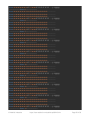
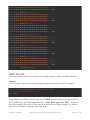
Memory Dump of a Mifare Classic 1K Card with an NDEF Record
[
Start of Memory Dump
]
------------------------Sector 0------------------------Block 0 3E 39 AB 7F D3 88 04 00 47 41 16 57 4D 10 34 08 >9« Ó?..GA.WM.4.
Block 1 14 01 03 E1 03 E1 03 E1 03 E1 03 E1 03 E1 03 E1 ...á.á.á.á.á.á.á
Block 2 03 E1 03 E1 03 E1 03 E1 03 E1 03 E1 03 E1 03 E1 .á.á.á.á.á.á.á.á
Block 3 00 00 00 00 00 00 78 77 88 C1 00 00 00 00 00 00 ......xw?Á......
------------------------Sector 1-------------------------
© Adafruit Industries
https://learn.adafruit.com/adafruit-pn532-rfid-nfc
Page 38 of 53
Block 4 00 00 03 11 D1 01 0D 55 01 61 64 61 66 72 75 69 ....Ñ..U.adafrui
Block 5 74 2E 63 6F 6D FE 00 00 00 00 00 00 00 00 00 00 t.comþ..........
Block 6 00 00 00 00 00 00 00 00 00 00 00 00 00 00 00 00 ................
Block 7 00 00 00 00 00 00 7F 07 88 40 00 00 00 00 00 00 ...... .?@......
------------------------Sector 2------------------------Block 8 00 00 00 00 00 00 00 00 00 00 00 00 00 00 00 00 ................
Block 9 00 00 00 00 00 00 00 00 00 00 00 00 00 00 00 00 ................
Block 10 00 00 00 00 00 00 00 00 00 00 00 00 00 00 00 00 ................
Block 11 00 00 00 00 00 00 7F 07 88 40 00 00 00 00 00 00 ...... .?@......
------------------------Sector 3------------------------Block 12 00 00 00 00 00 00 00 00 00 00 00 00 00 00 00 00 ................
Block 13 00 00 00 00 00 00 00 00 00 00 00 00 00 00 00 00 ................
Block 14 00 00 00 00 00 00 00 00 00 00 00 00 00 00 00 00 ................
Block 15 00 00 00 00 00 00 7F 07 88 40 00 00 00 00 00 00 ...... .?@......
------------------------Sector 4------------------------Block 16 00 00 00 00 00 00 00 00 00 00 00 00 00 00 00 00 ................
Block 17 00 00 00 00 00 00 00 00 00 00 00 00 00 00 00 00 ................
Block 18 00 00 00 00 00 00 00 00 00 00 00 00 00 00 00 00 ................
Block 19 00 00 00 00 00 00 7F 07 88 40 00 00 00 00 00 00 ...... .?@......
------------------------Sector 5------------------------Block 20 00 00 00 00 00 00 00 00 00 00 00 00 00 00 00 00 ................
Block 21 00 00 00 00 00 00 00 00 00 00 00 00 00 00 00 00 ................
Block 22 00 00 00 00 00 00 00 00 00 00 00 00 00 00 00 00 ................
Block 23 00 00 00 00 00 00 7F 07 88 40 00 00 00 00 00 00 ...... .?@......
------------------------Sector 6------------------------Block 24 00 00 00 00 00 00 00 00 00 00 00 00 00 00 00 00 ................
Block 25 00 00 00 00 00 00 00 00 00 00 00 00 00 00 00 00 ................
Block 26 00 00 00 00 00 00 00 00 00 00 00 00 00 00 00 00 ................
Block 27 00 00 00 00 00 00 7F 07 88 40 00 00 00 00 00 00 ...... .?@......
------------------------Sector 7------------------------Block 28 00 00 00 00 00 00 00 00 00 00 00 00 00 00 00 00 ................
Block 29 00 00 00 00 00 00 00 00 00 00 00 00 00 00 00 00 ................
Block 30 00 00 00 00 00 00 00 00 00 00 00 00 00 00 00 00 ................
Block 31 00 00 00 00 00 00 7F 07 88 40 00 00 00 00 00 00 ...... .?@......
------------------------Sector 8------------------------Block 32 00 00 00 00 00 00 00 00 00 00 00 00 00 00 00 00 ................
Block 33 00 00 00 00 00 00 00 00 00 00 00 00 00 00 00 00 ................
Block 34 00 00 00 00 00 00 00 00 00 00 00 00 00 00 00 00 ................
Block 35 00 00 00 00 00 00 7F 07 88 40 00 00 00 00 00 00 ...... .?@......
------------------------Sector 9------------------------Block 36 00 00 00 00 00 00 00 00 00 00 00 00 00 00 00 00 ................
Block 37 00 00 00 00 00 00 00 00 00 00 00 00 00 00 00 00 ................
Block 38 00 00 00 00 00 00 00 00 00 00 00 00 00 00 00 00 ................
Block 39 00 00 00 00 00 00 7F 07 88 40 00 00 00 00 00 00 ...... .?@......
------------------------Sector 10------------------------Block 40 00 00 00 00 00 00 00 00 00 00 00 00 00 00 00 00 ................
Block 41 00 00 00 00 00 00 00 00 00 00 00 00 00 00 00 00 ................
© Adafruit Industries
https://learn.adafruit.com/adafruit-pn532-rfid-nfc
Page 39 of 53
Block 41 00 00 00 00 00 00 00 00 00 00 00 00 00 00 00 00
Block 42 00 00 00 00 00 00 00 00 00 00 00 00 00 00 00 00
Block 43 00 00 00 00 00 00 7F 07 88 40 00 00 00 00 00 00
------------------------Sector 11------------------------Block 44 00 00 00 00 00 00 00 00 00 00 00 00 00 00 00 00
Block 45 00 00 00 00 00 00 00 00 00 00 00 00 00 00 00 00
Block 46 00 00 00 00 00 00 00 00 00 00 00 00 00 00 00 00
Block 47 00 00 00 00 00 00 7F 07 88 40 00 00 00 00 00 00
------------------------Sector 12------------------------Block 48 00 00 00 00 00 00 00 00 00 00 00 00 00 00 00 00
Block 49 00 00 00 00 00 00 00 00 00 00 00 00 00 00 00 00
Block 50 00 00 00 00 00 00 00 00 00 00 00 00 00 00 00 00
Block 51 00 00 00 00 00 00 7F 07 88 40 00 00 00 00 00 00
------------------------Sector 13------------------------Block 52 00 00 00 00 00 00 00 00 00 00 00 00 00 00 00 00
Block 53 00 00 00 00 00 00 00 00 00 00 00 00 00 00 00 00
Block 54 00 00 00 00 00 00 00 00 00 00 00 00 00 00 00 00
Block 55 00 00 00 00 00 00 7F 07 88 40 00 00 00 00 00 00
------------------------Sector 14------------------------Block 56 00 00 00 00 00 00 00 00 00 00 00 00 00 00 00 00
Block 57 00 00 00 00 00 00 00 00 00 00 00 00 00 00 00 00
Block 58 00 00 00 00 00 00 00 00 00 00 00 00 00 00 00 00
Block 59 00 00 00 00 00 00 7F 07 88 40 00 00 00 00 00 00
------------------------Sector 15------------------------Block 60 00 00 00 00 00 00 00 00 00 00 00 00 00 00 00 00
Block 61 00 00 00 00 00 00 00 00 00 00 00 00 00 00 00 00
Block 62 00 00 00 00 00 00 00 00 00 00 00 00 00 00 00 00
Block 63 00 00 00 00 00 00 7F 07 88 40 00 00 00 00 00 00
[
End of Memory Dump
................
................
...... .?@......
................
................
................
...... .?@......
................
................
................
...... .?@......
................
................
................
...... .?@......
................
................
................
...... .?@......
................
................
................
...... .?@......
]
NDEF Records
The above example contains two records, both located in sector 1 (sector 0 contains the MAD).
Record 1
The first record on the card can be identified by looking at the first byte of block 4 in sector 1.
Block 00 01 02 03 04 05 06 07 08 09 10 11 12 13 14 15 Char Value
----- ----------------------------------------------- -----------04
00 00
..
Every record on the Mifare card starts with the TLV Block (described above), and the first byte of
the TLV Block (the Tag Field) indicates that this is a NULL Block type (value 0x00). The second
byte is the Length Field, and is 0. Since there is no payload for this record (Length = 0), the third
byte of the TLV block is not present (the Value Field).
© Adafruit Industries
https://learn.adafruit.com/adafruit-pn532-rfid-nfc
Page 40 of 53
This record was likely inserted when the card was first formatted to ensure that at least one record
is present.
Record 2
The second record on the card starts at byte 0x02 of block 4 and continues into block 5.
Block 00 01 02 03 04 05 06 07 08 09 10 11 12 13 14 15 Char Value
----- ----------------------------------------------- -----------04
03 11 D1 01 0D 55 01 61 64 61 66 72 75 69 Ñ..U.adafrui
05
74 2E 63 6F 6D
t.com
Starting with the TLV Block data in the first two bytes, we can determine the following:
Byte(s) Value Description
------- ----- ----------04:02
0x03 Field Type (0x03 = NDEF Message)
04:03
0x11 Length Field (17 bytes)
This indicates to us that the record contains an NDEF Message (value 0x03), and that the message
is 17 bytes long (0x11 in hexadecimal = 17 in decimal value). This means that our NDEF message
is contained in the next 17 bytes (04:04..05:04). The NDEF record can then be analysed as follows:
© Adafruit Industries
https://learn.adafruit.com/adafruit-pn532-rfid-nfc
Page 41 of 53
Byte(s)
------04:04
Value Description
----- ----------0xD1 This byte is the **NDEF Record Header**, and indicates that this is
an NFC Forum Well Known Record (0x01 in the first 3 bits),
and that this is the first and last record (MB=1, ME=1),
and that this is a short record (SR = 1) meaning the payload
length is less than or equal to 255 chars (len=one byte).
TNF = 0x01 (NFC Forum Well Known Type)
IL = 0 (No ID present, meaning there is no ID Length or ID Field either)
SR = 1 (Short Record)
CF = 0 (Record is not 'chunked')
ME = 1 (End of message)
MB = 1 (Beginning of message)
04:05
0x01 This byte is the **Type Length** for the Record Type Indicator
(see above for more information), which is 1 byte (0x55/'U' below)
04:06
0x0D This is the payload length (13 bytes)
04:07
0x55 Record Type Indicator (0x55 or 'U' = URI Record)
04:08
0x01 This is the **start of the record payload**, which contains the
URI Identifier ("http://www.") since this is a URI Well-Defined
Record Type (see Well-Defined Records above). This will be
prepended to the rest of the URI that follows in the rest of the
message payload
04:09..05:04 ... The remainder of the URI ("adafruit.com"), which combined with the
pre-pended value from byte 04:08 yields: http://www.adafruit.com
TLV Terminator
Block 00 01 02 03 04 05 06 07 08 09 10 11 12 13 14 15 Char Value
----- ----------------------------------------------- -----------05
FE
þ
The final byte (block 5, byte 5), with the value 0xFE, is the TLV Terminator and indicates that this is
the end of the TLV Block.
© Adafruit Industries
https://learn.adafruit.com/adafruit-pn532-rfid-nfc
Page 42 of 53
Using with LibNFC
libnfc is a constantly moving target, and due to the frequent changes from one version to the
next we aren't able to offer libnfc support ourselves for the PN532. We can only guarantee
support and working code for the Arduino codebase that we maintain ourselves. The
information below is our best attempt at helping you get started with libnfc and the PN532
breakout, but it may require a bit of poking and prodding on your own depending on the library
version and platform you are working with. libnfc use is, unfortunately, at your own discretion.
Using the PN532 Breakout Boards with libnfc
libnfc (http://adafru.it/aSR) is a mature, cross-platform, open-source NFC library that can be easily
configured to work with the PN532 Breakout Board. While Linux is probably the easiest platform to
use libnfc with, it can be configured for the Mac and Windows as well, though you may need to dig
around on the libnfc Community Forums for some specific details on compiling .dlls for Windows,
etc.
If you want to test the PN532 Breakout Board out with libnfc, this simple tutorial should walk you
through the absolute basics of compiling and configuring libnfc, and using some of the canned
example SW included in the library.
This is only for using the PN532 breakout with an FTDI cable or FTDI Friend to a proper
computer. You cannot run LIbNFC on an Arduino or other microcontroller
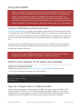
libnfc In Linux (Ubuntu 10.10 used in this example)
Step One: Download libnfc
Download the latest version of libnfc from Google Code (http://adafru.it/aSS) (ex. "libnfc1.4.1.tar.gz") and extract the contents of the file as follows:
$ wget http://libnfc.googlecode.com/files/libnfc-x.x.x.tar.gz
$ tar -xvzf libnfc-x.x.x.tar.gz
$ cd libnfc-x.x.x
Step Two: Configure libnfc for PN532 and UART
libnfc currently only supports communication over UART, using any inexpensive USB to UART
adapter like the FTDI Friend or a TTL FTDI cable. Before compiling, however, you will need to
configure libnfc to include support for UART and the PN532 chipset, which can be done with the
following commmand (executing in the folder where the above archive was unzipped):
© Adafruit Industries
https://learn.adafruit.com/adafruit-pn532-rfid-nfc
Page 43 of 53
$ ./configure --with-drivers=pn532_uart --enable-serial-autoprobe
Note: If you also wish to include debug output, you can add the '–enable-serial-autoprobe' flag
(minus the single quotes) to the configure options
Step Three: Build and install libnfc
You can build and install libnfc with the following three commands, also run from the folder where
the original archive was unzipped:
$ make clean
$ make
$ make install
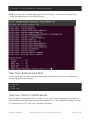
Step Four: Check for installed devices
Now that libnfc is (hopefully) built and installed, you can run the 'nfc-list' example to try to detect an
attached NFC board. Make sure the board is connected to the FTDI or USB/UART adapter, and that
it is connected to your PC, and run the following commands:
© Adafruit Industries
https://learn.adafruit.com/adafruit-pn532-rfid-nfc
Page 44 of 53
$ cd examples
$ ./nfc-list
This should list the devices that were detected
Step Five: Poll for an ISO14443A (Mifare, etc.) Card
Next, you can use the 'nfc-poll' example to wait 30 seconds for an ISO14443A card or tag and
display some basic information about this card. In the examples folder that we changed to above,
run the following command:
$ ./nfc-poll
This should give you some basic information on any card that entered the magnetic field within the
specified delay.
libnfc With Mac OSX Lion
scott-42 was kind of enough to post some tips on getting libnfc working on a Mac using an FTDI
adapter. A couple simple changes to the code were required (as of v1.6.0-rc1), with the
details here (http://adafru.it/aP1).
© Adafruit Industries
https://learn.adafruit.com/adafruit-pn532-rfid-nfc
Page 45 of 53
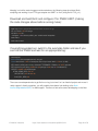
Keeping in mind the code changes mentionned above, the following steps should get libnfc
compiling and working via an FTDI type adapter and UART on Lion (using libnfc 1.6.0_rc1):
Download and build libnfc and configure if for PN532 UART (making
the code changes above before running make):
wget http://libnfc.googlecode.com/files/libnfc-1.6.0-rc1.tar.gz
tar -xvzf libnfc-1.6.0-rc1.tar.gz
cd libnfc-1.6.0-rc1
./configure --with-drivers=pn532_uart --enable-serial-autoprobe
sudo make
sudo make install
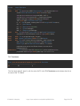
If everything worked out, switch to the examples folder and see if you
can find the PN532 and wait for an appropriate tag:
cd examples
Kevins-Mac-mini:examples kevin$ ./nfc-poll
/Users/kevin/libnfc-1.6.0-rc1/examples/.libs/nfc-poll uses libnfc 1.6.0-rc1 (r1326)
NFC reader: pn532_uart:/dev/tty.usbserial-FTE5WWPB - PN532 v1.6 (0x07) opened
NFC device will poll during 30000 ms (20 pollings of 300 ms for 5 modulations)
ISO/IEC 14443A (106 kbps) target:
ATQA (SENS_RES): 00 04
UID (NFCID1): 3e b9 6e 66
SAK (SEL_RES): 08
There are some dependencies to get libnfc running, but since it isn't an Adafruit project and we can't
really support it directly ourselves, you will probably have better luck looking at the libnfc
forums (http://adafru.it/aST) for Mac support. There are a few active users developping on the Mac.
© Adafruit Industries
https://learn.adafruit.com/adafruit-pn532-rfid-nfc
Page 46 of 53
FAQ
Some of the more common questions on the forums related to the PN532 NFC/RFID
Breakout (http://adafru.it/364) and NFC Shield (http://adafru.it/789).
Can I have multiple shields on one Arduino?
Nope, the I2C library can have only one address per bus and the address is not adjustable! So
one shield per Arduino please!
Can I read or write to Mifare tags with the PN532 and Adafruit Libraries?
Absolutely! The Adafruit libraries include functions to authenticate, read and write individual
blocks to Mifare Classic cards. Before you can read or write a block you need to authenticate it
with the appropriate key, and once the block is authenticated you can read and write to your
hearts content)!
For example, the key functions in the I2C library (http://adafru.it/aSW) (which was written to go
along with the NFC shield (http://adafru.it/789) since it defaults to I2C) are:
uint8_t mifareclassic_AuthenticateBlock (uint8_t * uid, uint8_t uidLen,
uint32_t blockNumber, uint8_t keyNumber,
uint8_t * keyData);
uint8_t mifareclassic_ReadDataBlock (uint8_t blockNumber, uint8_t * data);
uint8_t mifareclassic_WriteDataBlock (uint8_t blockNumber, uint8_t * data);
This is all you need to start reading and writing data, and you can verify the data using one of many
Android applications that support working with Mifare cards (a search for NFC will turn up plenty).
What level of NDEF support is included in the libraries?
At the moment, all NDEF (http://adafru.it/aXr) features are experimental and incomplete. Only
very basic test code has been written to format a card for NDEF messages in a way that any
NFC-enabled Android phone should be able to understand it, and it was written and an
extremely simple proof of concept.
We would like to improve NDEF support for Mifare tags in the near future and some initial
planning has gone into this, but at the moment our suggestion is to stick to plain text and 'vanilla'
Mifare Classic (http://adafru.it/aXs) reads and writes. You can read and write Mifare Classic and
Mifare Ultralight blocks from Android, and you don't need to used the more complicated NDEF
standard to simply pass data back and forth via a Mifare Classic or Ultralight card.
Note: Please use the limited NDEF code with care. Formatting cards for NDEF support is
currently a one way operation, and should only be performed on cards you can dedicate to
NDEF use.
© Adafruit Industries
https://learn.adafruit.com/adafruit-pn532-rfid-nfc
Page 47 of 53
Does the PN532 support peer to peer communication to talk with my smartphone?
Yes, the PN532 supports peer to peer communication, but the SW support for this isn't
implemented in the Adafruit libraries.
Peer to peer communication with Android is possible, for example, but the actual implementation
is quite complicated on the PN532 side. You need to go through a lot of SW layers to
communicate with Android in a way that it understands -- it would require developing a full NDEF
stack for the messages, SNEP and LLCP stacks, etc. -- which is unfortunately well beyond the
scope of what we can offer on a development board at this price point.
All of the HW requirements for this are met with the Adafruit shield and breakout board, but the
stack implementation is non trivial and would require us to charge a significant premium for these
boards if we implemented this.
We've focused our energy on providing a reliable, proven, properly-tuned HW reference, and
enough of a SW building block to get everyone started, but there are too many holes to fill in to
cover everything NFC can do with a development board at this price point.
For an example of communicating with a phone via NFC, though, have a look at "Talking With
Your Arduino via NFC on Blackberry (http://adafru.it/aXt)" which uses the Adafruit NFC Shield.
The SW layers required for NFC-based P2P communication with a Blackberry device are
apparently much lower than on Android.
Does the PN532 support tag emulation?
Yes, but in reality it's impossible to implement since it requires an external 'secure
element (http://adafru.it/aXu)' that is very difficult to source (under export control and general
NDA from the few manufacturers of them). If you can get one we'd love to see it, though!
Can the PN532 read Tag-It tags from TI?
No. The PN532 is designed to be used with ISO14443 (http://adafru.it/aSU) tags, with Mifare
Classic probably the most common general-purpose tag type in use. For more information on
supported tags
seehttp://www.libnfc.org/documentation/hardware/tags/iso14443 (http://adafru.it/aSV) or search
for information on the common Mifare tag family based on ISO1443A.
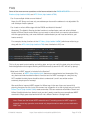
Can I set a delay calling readPassiveTargetID()?
Note: This question only applies to the I2C Library (http://adafru.it/aSW). The SPI
library (http://adafru.it/aSX) doesn't handle the timing the same way.
readPassiveTargetID() intentionally waits around in a blocking delay until a card enters the
magnetic field. The reason for this blocking delay is to ensure a well-understood
command/response flow. Once the magnetic field is activated and a read request is sent via
readPassiveTargetID, you can keep sending new commands to the PN532, but the moment a
card or tag enters the field, the PN532 will send a response to the initial read request, even if it's
© Adafruit Industries
https://learn.adafruit.com/adafruit-pn532-rfid-nfc
Page 48 of 53
in the middle of some other response or activity. To avoid having to debug this in SW, a blocking
delay was implemented to keep the command/response pattern as clear as possible.
As a workaround to this blocking-delay limitation, setPassiveActivationRetries(maxRetries)
was added to the latest NFC libraries to allow you to set a specific timeout after read requests.
By default, the PN532 will wait forever for a card to enter the field. By specifying a fixed number
of retries via MxRtyPassiveActivation (see UM section 7.3.1 describing the RFConfiguration
register, specifically CfgItem 5) the PN532 will abort the read request after specified number of
attempts, and you can safely send new commands without worrying about mixing up response
frames. To wait forever, set MxRtyPassiveActivation to 0xFF. To timeout after a fixed number of
retries, set MxRtyPassiveActivation to anything less than 0xFF.
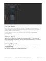
Example Sketch:
#include <Wire.h>
#include <Adafruit_NFCShield_I2C.h>
#define IRQ (2)
#define RESET (3) // Not connected by default on the NFC Shield
Adafruit_NFCShield_I2C nfc(IRQ, RESET);
void setup(void) {
Serial.begin(115200);
Serial.println("Hello!");
nfc.begin();
uint32_t versiondata = nfc.getFirmwareVersion();
if (! versiondata) {
Serial.print("Didn't find PN53x board");
while (1); // halt
}
// Got ok data, print it out!
Serial.print("Found chip PN5"); Serial.println((versiondata>>24) & 0xFF, HEX);
Serial.print("Firmware ver. "); Serial.print((versiondata>>16) & 0xFF, DEC);
Serial.print('.'); Serial.println((versiondata>>8) & 0xFF, DEC);
// Set the max number of retry attempts to read from a card
// This prevents us from waiting forever for a card, which is
// the default behaviour of the PN532.
nfc.setPassiveActivationRetries(0xFF);
// configure board to read RFID tags
© Adafruit Industries
https://learn.adafruit.com/adafruit-pn532-rfid-nfc
Page 49 of 53
// configure board to read RFID tags
nfc.SAMConfig();
Serial.println("Waiting for an ISO14443A card");
}
void loop(void) {
boolean success;
uint8_t uid[] = { 0, 0, 0, 0, 0, 0, 0 }; // Buffer to store the returned UID
uint8_t uidLength;
// Length of the UID (4 or 7 bytes depending on ISO14443A card type)
// Wait for an ISO14443A type cards (Mifare, etc.). When one is found
// 'uid' will be populated with the UID, and uidLength will indicate
// if the uid is 4 bytes (Mifare Classic) or 7 bytes (Mifare Ultralight)
success = nfc.readPassiveTargetID(PN532_MIFARE_ISO14443A, &uid[0], &uidLength);
if (success) {
Serial.println("Found a card!");
Serial.print("UID Length: ");Serial.print(uidLength, DEC);Serial.println(" bytes");
Serial.print("UID Value: ");
for (uint8_t i=0; i < uidLength; i++)
{
Serial.print(" 0x");Serial.print(uid[i], HEX);
}
Serial.println("");
// Wait 1 second before continuing
delay(1000);
}
else
{
// PN532 probably timed out waiting for a card
Serial.println("Timed out waiting for a card");
}
}
Hey wait ... isn't there something funny with the SVDD pin?
Indeed, good eye! Unfortunately, both v1.0 and v1.3 of the breakout boards have a problem on
the schematic. SVDD is connected directly to VDD, but should be left floating since it is used to
power secure modules. This has no effect on the functionality of the boards, but does cause
some extra current to be drawn. It will be fixed on the next revision of the board, but if you
require the use of the secure modules (rare), you can simply cut the trace to the left of C22,
which is the cap connected to SVDD (just follow the trace straight up from pin 37).
Are there any special requirements to use the PN532 Breakout with the Due?
While the libraries do not officially support the Due yet, some customers have been able to get
them working with some minor changes to the library.
© Adafruit Industries
https://learn.adafruit.com/adafruit-pn532-rfid-nfc
Page 50 of 53
We recommend using the I2C libraries with both the shield and the breakout boards since the
I2C library represents the latest code from Adafruit, and the shield version should work without
too much effort.
There is one caveat combining the breakout, I2C and the Due, though: The Due includes
pullup resistors for I2C0 (SCL0 and SDA1), but there are no pullups resistors on SCL1
and SDA1. SCL1/SDA1 are the pins used as replacements for the Uno I2C pins (the pins used
on standard shields), so you will need to add two 1.5K pullups on SCL1 and SDA1 to use the
breakout board with I2C1 and the Due. Simply solder two 1.5K resistors, one from SCL1 to 3V3
and another from SDA1 to 3.3V, and then connect the board the same way you would with an
Uno.
This issue only applies to the PN532 Breakout board since the PN532 shield includes I2C
pullup resistors right on board.
© Adafruit Industries
https://learn.adafruit.com/adafruit-pn532-rfid-nfc
Page 51 of 53
Downloads
SPI and I2C library is available from github (http://adafru.it/aSX)
Deprecated I2C-only library is available from github (http://adafru.it/aSW)
Version 1.6 schematic
(click to enlarge)
Version 1.3 schematic
(click to enlarge)
© Adafruit Industries
https://learn.adafruit.com/adafruit-pn532-rfid-nfc
Page 52 of 53
PN532 Breakout v1 Schematic
http://adafru.it/d7l
You can also grab the Eagle CAD PCB files from github:
https://github.com/adafruit/Adafruit-PN532-RFID-NFC-Shield (http://adafru.it/dik)
https://github.com/adafruit/Adafruit-PN532-RFID-NFC-Breakout (http://adafru.it/dil)
© Adafruit Industries
Last Updated: 2015-07-30 12:20:14 PM EDT
Page 53 of 53