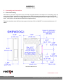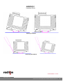
1
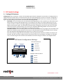
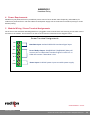
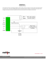
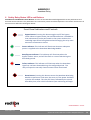
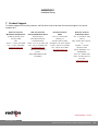
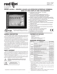
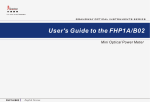
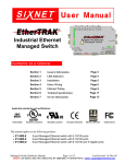
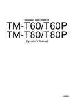
Watchdog Relay
6HBWDOG1
User Manual
September 2013
www.redlion.net
6HBWDOG1
Heartbeat Relay
CHANGE HISTORY
Version
R01
Date
Description
9/2013 First Draft Revision
Connect.Monitor. Control.
www.redlion.net
Version u01 © 2013. Red Lion Controls. All Rights Reserved.
2
6HBWDOG1
Heartbeat Relay
TABLE OF CONTENTS
1
General Information ............................................................................................................................................5
1.1
Overview .......................................................................................................................................................... 5
1.2
Specifications ................................................................................................................................................... 5
1.2.1
2
3
4
5
6
7
General Specifications ................................................................................................................................. 5
1.3
Getting Started with Red Lion Controls Hardware ............................................................................................. 7
Assembly and Instruction ....................................................................................................................................8
2.1
Panel Assembly................................................................................................................................................. 8
DIP-Switch Settings ........................................................................................................................................... 10
3.1
Setting DIP-Switches ....................................................................................................................................... 10
Power Requirements ......................................................................................................................................... 12
Module Wiring / Screw Terminal Assignments ................................................................................................... 12
Safety Relay Status LED’s and buttons................................................................................................................ 14
Product Support ................................................................................................................................................ 15
Connect.Monitor. Control.
www.redlion.net
Version u01 © 2013. Red Lion Controls. All Rights Reserved.
3
6HBWDOG1
Heartbeat Relay
INSTALLATION AND HAZARDOUS AREA WARNINGS
These products should not be used to replace proper safety interlocking. No software-based device (or any
other solid-state device) should ever be designed to be responsible for the maintenance of consequential
equipment or personnel safety. In particular, Red Lion Controls disclaims any responsibility for damages, either
direct or consequential, that result from the use of this equipment in any application.
In addition to operation and maintenance instructions the following items appear in the manufacturer’s
installation instructions.
1. "THIS EQUIPMENT IS SUITABLE FOR USE IN CLASS I, DIVISION 2, GROUPS A, B, C, D OR NONHAZARDOUS LOCATIONS ONLY".
2. "WARNING - EXPLOSION HAZARD - SUBSTITUTION OF ANY COMPONENTS MAY IMPAIR
SUITABILITY FOR CLASS I, DIVISION 2".
3. "WARNING - EXPLOSION HAZARD - DO NOT DISCONNECT EQUIPMENT UNLESS POWER HAS
BEEN SWITCHED OFF OR THE AREA IS KNOWN TO BE NON-HAZARDOUS".
4. WARNING – EXPOSURE TO SOME CHEMICALS MAY DEGRADE THE SEALING PROPERTIES OF
MATERIALS USED IN THE SEALED RELAY DEVICE.
5. FIELD WIRING CONDUCTOR MINIMUM INSULATION RATING: 75°C.
6. DEVICE IS OPEN-TYPE AND IS TO BE INSTALLED IN A TOOL ONLY ACCESSIBLE ENCLOSURE
SUITABLE FOR THE ENVIRONMENT.
These products are operator interface units to be used within control panels. These devices are intended for
use in Class I, Division 2, Hazardous Locations, industrial control applications. The enclosure shall be suitable
for the location.
A minimum IP54 rated enclosure is needed for ATEX unless an equivalent degree of protection is supplied by
the location.
Connect.Monitor. Control.
www.redlion.net
Version u01 © 2013. Red Lion Controls. All Rights Reserved.
4
6HBWDOG1
Heartbeat Relay
These products are to be used within control panels in hazardous locations. The enclosure shall be suitable
for this location. Hot-swapping is not for use in hazardous locations.
Note: All information in this document applies to 6HBWDOG1 except where otherwise noted. Refer to
http://www.redlion.net or online help systems for detailed product specifications and configuration settings.
1
General Information
1.1 Overview
The Red Lion heartbeat relay module is used as a failsafe system to monitor and shut down a PLC or RTU
based automation system in the event of a malfunction in the processor controlling the system. A secondary
safety check is the most economical way to achieve system safety shutdown.
This is accomplished is by powering the control system through the internal 10A rated relay built into the
watchdog module. Loss of processor control is detected by monitoring a discrete output signal designated as
the “Heartbeat” which toggles on and off under processor control. If the processor malfunctions, the heartbeat
will cease to toggle and the Heartbeat Watchdog Module will sense this failure and shut down the system by
opening the relay powering the system.
The Heartbeat Watchdog Module is designed for extreme reliability, using no microprocessor or other
programmable logic elements in its design. Using hard wired logic elements in place of CPU and memory
based circuitry removes the possibility of program bugs or memory failure disrupting the operation of the
module.
1.2 Specifications
1.2.1
General Specifications
Environmental
Power Supply voltage: 12-24 VDC
Operating Temperature: -40 to +80 C (-40 to +85 C Storage)
Humidity: 5 to 95% RH (non-condensing)
Standards Compliance
Electrical Safety UL 508, CSA C22.2/142; IEC61010-1; CE
EMI Emissions FCC part 15, ICES-003, Class A; EN55022 IEC 61000-6-4; CE
EMC Immunity IEC61000-6-2 (EN61000-4-2,3,4,5,6,8); CE
Vibration: IEC60068-2-6
Shock: IEC60068-2-27
Hazardous locations (Class 1, Div II, Groups A, B, C, D), ISA 12.12.01, CSA C22.2/213, ATEX
(Zone 2), IEC 60079-0, -15 (pending)
Marine and offshore tested and/or verified to meet various marine and maritime standards such as
Connect.Monitor. Control.
www.redlion.net
Version u01 © 2013. Red Lion Controls. All Rights Reserved.
5
6HBWDOG1
Heartbeat Relay
ABS, DNV No. 2.4 and Lloyds (pending)
Packaging Impact resistant Lexan® polycarbonate
Ingress Protection: IP30
Dimensions: 1.00” (2.54 cm) width x 4.00” (10.16 cm) height x 3.72” (9.45 cm) length
Heartbeat Input
Voltage range: 10 – 30 VDC
Input Polarity: Sourcing
Input isolation: 150 Volts
Guaranteed ON voltage: 9 VDC
Guaranteed OFF voltage: 1.0 VDC
Guaranteed OFF current: 1.0 mA DC
Input resistance (@24VDC): 2.6 Kohms
Input current (@ 24 VDC): 10 mA
Input Protection: High Impedance with overvoltage protection
Heartbeat Frequency: 1 – 50Hz*
Heartbeat timeout (configurable): 1s to 200s*
* 1Hz may not work at fastest heartbeat timeout time of 1 second
Output Circuit
Relay type: Form C
Maximum switching voltage: 30 VDC
Rated operational current: 2A@30VDC
Connect.Monitor. Control.
www.redlion.net
Version u01 © 2013. Red Lion Controls. All Rights Reserved.
6
6HBWDOG1
Heartbeat Relay
1.3 Getting Started with Red Lion Controls Hardware
Following these steps will make installation and start-up easier.
1. Mount the Hardware
If you purchased individual components, consult section 2 of this manual or other appropriate user manual
for information on installing them into an enclosure.
2. Connect Power and Heartbeat input
Connect AC power cables from a suitable power source to the 24V DC power supply. The DC power
connections are then attached to the watchdog relay bases as outlined in section 5.
3. Connect the PLC/instruments to the form C relay
Please refer to section 5 to see how wiring should be completed.
4. Configure DIP switch settings
To configure the heartbeat timeout and boot delay set the dip switches on the side of the module according
to the instructions found in section 3 of this document.
5. Apply Power
Apply power to the watchdog relay power input and the form C relay that will power the PLC/instruments.
This will power up the watchdog relay and the PLC/instruments, but since no heartbeat pulse is configured
the form C relay will be deactivated after the boot delay time expires.
6. Press the bypass button to enable bypass mode.
Using a pen or a small screw driver press the bypass button on the front of the watchdog relay, once. The
boot/bypass LED will illuminate and remain ON until the button is pressed again. The bypass mode will
activate the form C relay so power will be applied to the PLC/instruments connected to the relay.
7. Apply the heartbeat pulse from the SCADA system/Controller/RTU/PLC
The heartbeat is usually generated by adding logic into the device that the heartbeat relay will be
monitoring. For devices using an IEC61131-3 programming language a pulse can be created by adding a
“blink” function. Define how often the pulse will cycle and set the output to a physical discrete output. The
blink rate of the heartbeat pulse should be less (faster) than the heartbeat timeout configured in the dip
switches.
8. Press the bypass button again to disable bypass mode.
Pressing the bypass button again will disable bypass mode. Since the heartbeat pulse is now present the
relay will remain active.
9. If You Have Difficulty
If you experience startup trouble, go to the Getting Started icon in the I/O Tool Kit online help for some
troubleshooting tips or go to http://www.redlion.net. If you still need assistance then please contact Red
Lion Controls at +1 (717) 767-6511.
Connect.Monitor. Control.
www.redlion.net
Version u01 © 2013. Red Lion Controls. All Rights Reserved.
7
6HBWDOG1
Heartbeat Relay
2
Assembly and Instruction
2.1 Panel Assembly
Most Red Lion Controls components snap onto DIN rail strips fastened to a subpanel. The watchdog relay can
snap on the DIN rail vertically by hooking the top of the DIN rail mounting bracket on the top of the DIN rail,
then pressing down (See the mounting diagrams below). The watchdog relay module is approximately 4” high
and 1” wide (refer to the Mechanical Dimensions diagram below).
The screw terminals size is M3 and can support wire sizes of 30 to 12AWG. The recommended torque is 5
IN/LB.
Mechanical Dimensions
Connect.Monitor. Control.
www.redlion.net
Version u01 © 2013. Red Lion Controls. All Rights Reserved.
8
6HBWDOG1
Heartbeat Relay
Applying to DIN-Rail
Removing from DIN-Rail
Connect.Monitor. Control.
www.redlion.net
Version u01 © 2013. Red Lion Controls. All Rights Reserved.
9
6HBWDOG1
Heartbeat Relay
3 DIP-Switch Settings
3.1 Setting DIP-Switches
Configuration: Once installed in a system, the heartbeat signal must be configured. The controller is configured first to
toggle the discrete output which is connected to IN+/IN- at the desired frequency. Once the controller is configured in
this way the DIP switches located on the top of the Heartbeat Watchdog Module can be set to monitor the heartbeat
signal. Two time settings are provided in the Heartbeat Watchdog Module:
Boot Delay: This time setting causes the Heartbeat Watchdog Module to wait a specific time after Power-Up or
Reset before monitoring the Heartbeat Input. The purpose for this delay is to provide sufficient time for the
system controller to boot up and begin toggling the heartbeat signal before the Heartbeat Watchdog Module
begins monitoring the signal. This time delay setting should be configured to account for the worst case boot
time of the system. If the boot delay is set too short, the Heartbeat Watchdog module will sense the lack of
input signal changes while the system boots as a failure of the system.
Heartbeat Timeout: This time setting defines the maximum period between rising edges of the Heartbeat input
signal which indicates proper operation of the system. If the Heartbeat input period exceeds this time setting,
then the Heartbeat Watchdog Module will detect this as a failure of the system.
Each time setting is assigned to four DIP switches, and each group of four switches is divides into two pairs of
switches. One pair is used to configure a base time and the other pair will configure a multiplier for that base
time, so a wide range of times can be accommodated. The switch settings are shown in the diagram below:
DIP Switch Configuration Settings
Time Switch Positions
Boot
Delay
Heartbeat
Timeout
Time
1 Second
5 Seconds
10 Seconds
25 Seconds
1 2 3 4 5 6 7 8
Multiplier Switch Positions
Time
Time
Multiplier Multiplier
Timex1
Timex2
Timex4
Timex8
Connect.Monitor. Control.
www.redlion.net
Version u01 © 2013. Red Lion Controls. All Rights Reserved.
10
6HBWDOG1
Heartbeat Relay
As an example, if the intention is to set a boot delay of 100 seconds, switches 1-2 would both be set in the up
position for a time of 25 seconds, and switches 3-4 would be set down (3) and up (4) for a multiplier of 4. This
setting provides 25 seconds x4 for 100 seconds boot delay.
Another example using the heartbeat timeout switches for a desired heartbeat period of 5 seconds would be:
switches 5-6 set up (5) and down (6) for a 5 second time, while switches 7-8 would both be set down for a x1
multiplier. 5 seconds x 1 yields a heartbeat interval of 5 seconds. Power Wiring Alternatives
Connect.Monitor. Control.
www.redlion.net
Version u01 © 2013. Red Lion Controls. All Rights Reserved.
11
6HBWDOG1
Heartbeat Relay
4
Power Requirements
Modules may be powered from any suitable DC power source of 10 to 30 VDC. Most frequently, EtherTRAK-2 I/O
modules are powered from a +24 VDC industrial rated power supply such as the Sixnet ET-PS-024-02 (2 Amp) or ST-PS024-05 (5 Amp).
5
Module Wiring / Screw Terminal Assignments
On the face of the Heartbeat Watchdog Module is a pluggable screw terminal block with retaining screws which secure
the block to the module. The connections on the screw terminals are described in the diagram below.
Screw Terminal Assignments
IN+
Heartbeat Input: Isolated 10-30VDC Heartbeat Signal Input
INN.C.
COM
Form C Relay Output: 10A@250VDC (5A@30VDC) Relay will
connect N.O. to COM when Heartbeat signal is valid. N.C. to
COM will connect if Heartbeat is lost.
N.O.
V+
Power Input: 10-30VDC power input to module power supply.
GND
Connect.Monitor. Control.
www.redlion.net
Version u01 © 2013. Red Lion Controls. All Rights Reserved.
12
6HBWDOG1
Heartbeat Relay
An example of wiring from watchdog module to power supply and external devices is below. When the heartbeat pulse
is present on “IN +” input the product powered by the relay will be powered. When the heartbeat pulse stops for the
configured heartbeat timeout the optional external lamp will be powered to indicate an alarm state.
Connect.Monitor. Control.
www.redlion.net
Version u01 © 2013. Red Lion Controls. All Rights Reserved.
13
6HBWDOG1
Heartbeat Relay
6
Safety Relay Status LED’s and Buttons
LED Indicators and Manual Control Buttons: The face of the Heartbeat Watchdog Module has two pushbuttons and
three LED status indicators. The pushbuttons are recessed to prevent accidental depresses. The location and function of
these items are defined in the diagram below:
Front Panel Indicators and Controls
Bypass Button: Pressing this button toggles on/off the bypass
mode. When in bypass mode, the Heartbeat Monitor is disabled so
that maintenance can be performed on the system without the
watchdog input failure being detected and changing the relay state
during the maintenance period.
Power Indicator: This indicator will illuminate whenever adequate
power is supplied to the Heartbeat Watchdog Module.
Boot/Bypass Indicator: This indicator will illuminate when the
bypass mode is active, and will also flash at a rate of 4Hz during the
boot delay period.
Failure Indicator: This indicator will illuminate when the Heartbeat
signal has not been detected during the configured period. The
relay will open the normally closed contacts when illuminated.
Reset Button: Pressing this button causes the Heartbeat Watchdog
Module to perform a hard reset, the same as if the power had been
cycled to the module. The relay will close, followed by the normal
boot delay time, after which heartbeat input monitoring will begin.
Connect.Monitor. Control.
www.redlion.net
Version u01 © 2013. Red Lion Controls. All Rights Reserved.
14
6HBWDOG1
Heartbeat Relay
7 Product Support
To obtain support for Red Lion products, call Red Lion Controls and ask for technical support. Our phone
numbers are:
Red Lion Controls
Red Lion Controls
Red Lion Controls
Worldwide Headquarters
Europe Middle East Africa
China
India Sales Office
20 Willow Springs Circle
Softwareweg 9
Unit 101, XinAn Plaza
201 - B, 2nd Floor, Park
York PA 17406
3821 BN Amersfoort
Building 13
Centra
USA
The Netherlands
No.99 Tianzhou Road
Opp. 32 Mile Stone, Sector -
Phone: +1 (877) 432-9908
Phone: +31 (0) 33-4723-225
ShangHai, P.R. China 200223
30
Fax: +1 (717) 764-0839
Fax: +31 (0) 33-4893-793
Phone: +86 21 6113-3688
Gurgaon - 122 002
[email protected]
[email protected]
Fax: +86 21 6113-3683
Haryana, India
Toll Free from UK and
[email protected]
Phone: Bangalore +91
France:
Red Lion Controls
9844876540
00800 REDLIONS (00800
Pune +91 7350011645
733 54667)
Delhi +91 9627115115
Fax: N/A
[email protected]
Connect.Monitor. Control.
www.redlion.net
Version u01 © 2013. Red Lion Controls. All Rights Reserved.
15