1
T24-RA
Potentiometer Acquisition Module
User Manual
mantracourt.com
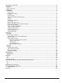
Introduction / Overview ........................................................................................................2
Connections .......................................................................................................................2
Power ............................................................................................................................. 2
Input Connections .............................................................................................................. 2
Configuration ......................................................................................................................3
Installation ...................................................................................................................... 3
T24 Toolkit.................................................................................................................... 3
T24-BSu Base Station ....................................................................................................... 3
T24 Toolkit ...................................................................................................................... 4
General Pages ................................................................................................................ 4
Setup Base Station Communications ..................................................................................... 4
Home .......................................................................................................................... 5
Analyser ....................................................................................................................... 6
Data Provider Monitor ...................................................................................................... 7
Information ................................................................................................................... 8
Battery and Radio Levels ................................................................................................... 9
Battery and Radio Levels Advanced Settings ......................................................................... 10
Data Rates and Quality ................................................................................................... 11
Input / Output Configuration ............................................................................................ 13
Calibration By Certificate ................................................................................................ 15
Calibration Advanced ..................................................................................................... 16
Channel and Encryption .................................................................................................. 18
Save and Restore .......................................................................................................... 19
Advanced Settings ......................................................................................................... 20
Installation ....................................................................................................................... 21
Overview ....................................................................................................................... 21
Power Supply / Battery ..................................................................................................... 22
Considerations When Selecting Batteries ............................................................................. 22
Battery Types .............................................................................................................. 23
Power Supply Modules .................................................................................................... 23
Lithium Ion /Polymer Module T24-BC1 .............................................................................. 23
Physical Connections ................................................................................................ 24
Specification .......................................................................................................... 24
Suitable Batteries .................................................................................................... 24
Capacitor Module T24-BC2 ............................................................................................ 25
Mounting ....................................................................................................................... 26
Antenna ........................................................................................................................ 27
Internal Chip Antenna .................................................................................................... 27
External Antenna Option ................................................................................................. 27
External Antennas ......................................................................................................... 28
Antenna Orientation ...................................................................................................... 28
Specifications ................................................................................................................... 29
General Radio ................................................................................................................. 29
T24-RA.......................................................................................................................... 29
Approvals ........................................................................................................................ 30
CE ............................................................................................................................... 30
FCC.............................................................................................................................. 30
Industry Canada .............................................................................................................. 31
OEM / Reseller Marking and Documentation Requirements .......................................................... 31
FCC.............................................................................................................................. 31
IC ................................................................................................................................ 31
CE ............................................................................................................................... 31
Declaration Of Conformity ................................................................................................... 33
Worldwide Regional Approvals .............................................................................................. 34
Important Note ............................................................................................................ 34
Warranty ......................................................................................................................... 34
1
Mantracourt Electronics Limited T24-RA User Manual
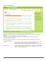
Introduction / Overview
The T24-RA is a remote acquisition module for the collection and processing of potentiometer resistance
measurements. The module measures the resistance and periodically transmits it. Between transmissions the
device is optionally in a power saving sleep mode to conserve batteries
Various devices are available that utilise the transmitted data and include handheld and PC displays etc.
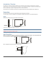
Connections
This section will show you how to get the device pair working out of the box.
You will require a 3 Volt dc supply for the acquisition module which may be 2 X AA alkaline batteries.
Power
Attach power supply wiring to the module as shown below:
+ 3V Supply
0V Supply
Connect to a 3 Volt power supply or batteries.
WARNING: This module is not reverse polarity protected!
WARNING: The maximum voltage is 3.6V!
Input Connections
NOTE: The acquisition module may already be mounted in a connectivity module. In this case please refer
to the connectivity module user manual for the connection details.
SHLD
GND
In +
+ 2V5
Basic configuration with potentiometer shown below:
0%
100%
Mantracourt Electronics Limited T24-RA User Manual
SHLD
EXC N/C
In+
EXC +
2
Configuration
This section explains how to install software and configure the module. Please note that you will need the T24
Toolkit software and a T24-BS base station to allow your computer to communicate with T24 telemetry
devices.
Installation
T24 Toolkit
To configure the devices we must use the T24 Toolkit software application. This can be downloaded from our
web site or may be shipped with your products.
Install this on a PC or laptop.
Run setup.exe and follow the prompts to install the software.
T24-BSu Base Station
If you have a USB version of the base station (T24-BSu) then you just need to plug this into a USB socket on your
PC. If you are using an alternative base station then please refer to the appropriate manual.
3
Mantracourt Electronics Limited T24-RA User Manual
T24 Toolkit
The T24 Toolkit provides a means of simple configuration and calibration of the acquisition module along with
useful tools to aid integration.
Run the T24 Toolkit software application.
PLEASE NOTE: Depending on which acquisition module is selected the screenshots may vary slightly. This will generally be in naming of
units and device descriptions. The screenshots shown are those shown when a T24-PA strain gauge acquisition module is connected.
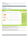
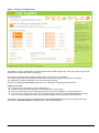
General Pages
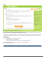
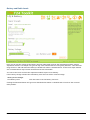
Setup Base Station Communications
Select USB as the interface and select 1 as the Base Station Address.
In the toolkit all items that can be changed by the user are coloured orange.
To change a value just click on the relevant orange item. You will then be presented with a new dialog window
allowing you to change the value.
This may use a slider, text box or list to allow your new value to be entered.
Click the Home button to attempt communications with the base station.
If no communications can be established the toolkit will remain on this page. You will need to check that the
base station is powered and that it is connected to the converter correctly.
Mantracourt Electronics Limited T24-RA User Manual
4
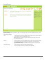
Home
We now have successful communications with the base station so we can now pair with our device or we can
select the Spectrum Analyser mode or Data Provider Monitor mode.
To connect to our device we will pair. This is achieved by power cycling the device. Pairing removes the need
to know the radio settings of the device you are connecting to and also ensures that it is in a suitable state for
configuration.
Pairing
Procedure
Remove power from the acquisition module
Click the Pair button on the toolkit.
You now have 10 seconds to re-apply power to the acquisition module.
If you connect successfully the toolkit will change to the Information page.
If the pairing fails try again.
NOTE: Pairing with the toolkit will not change the radio configuration settings of the connected device.
5
Mantracourt Electronics Limited T24-RA User Manual
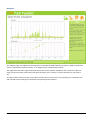
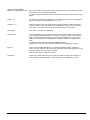
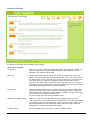
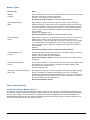
Analyser
The analyser page is provided as a tool and will not normally be needed unless you plan to change channels and
want to find the best channel to select, or to diagnose poor communications issues.
This page shows the radio signal levels detected across all the channels available to the T24 series of devices.
Using this tool may help in detecting noisy areas and allow you to decide on which channels you may want to
use.
The above charts show the traffic from a Wi-Fi network and it can be seen to be operating over channels 6 to 9
and it would be best (though not essential) to avoid using these channels.
Mantracourt Electronics Limited T24-RA User Manual
6
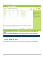
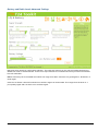
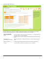
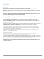
Data Provider Monitor
T24 acquisition devices normally operate in low power mode and periodically transmit Data Provider
packets
This page shows all detected Data Provider packets which may be useful for checking that a device is
operational.
NOTE: When the toolkit connects to a device to enable configuration it will usually inhibit the transmission of Data Provider packets.
The Start Logging button will ask for a filename and proceed to log the received data to a CSV file in the
following format:
Data Tag, Elasped mS, Value
The View Last Log button will launch the application associated with CSV files and open the last logged file.
7
Mantracourt Electronics Limited T24-RA User Manual
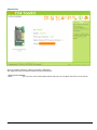
Information
Once successfully paired to a device this page is displayed.
This page shows you information about the connected device.
Items you can change:
Name
You can enter a short description which may help you recognise this device in the future.
Mantracourt Electronics Limited T24-RA User Manual
8
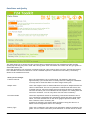
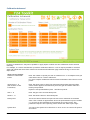
Battery and Radio Levels
Here you can see the voltage of the battery and the radio signal levels at the base station and the remote
acquisition module. This simple view gives an LQI value which stands for Link Quality Indicator. This value will
range from 0 to 100 and within this band you should still achieve communications. As the level drops towards
zero communications may become intermittent but still achievable.
You can set the level at which the acquisition module reports a low battery.
If the battery voltage is below the Low Battery Level the bar will be coloured orange.
Items you can change:
Low Battery Level
Click this item to set the battery low level.
Clicking the Advanced button will give more detailed information on the RSSI and CV levels of the received
radio packets.
9
Mantracourt Electronics Limited T24-RA User Manual
Battery and Radio Levels Advanced Settings
LQI value which stands for Link Quality Indicator. This value will range from 0 to 100 and within this band you
should still achieve communications. As the level drops towards zero communications may become intermittent
but still achievable.
RSSI is effectively the received dB level which will range from about -30 which is a good signal to -90 which is a
weak signal.
CV is the correlation value and indicates how well the signal can be decoded. This ranges from 55 which is a
poor quality signal and 110 which is an excellent signal.
Mantracourt Electronics Limited T24-RA User Manual
10
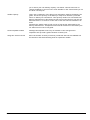
Data Rates and Quality
This page allows you to select the rate at which data is transmitted from the acquisition module and the
quality. By selecting low power mode and entering some other information the toolkit will also give guides on
achievable battery life.
Note that the battery life calculator is assuming the best case scenario which is at 20°C and that the battery
has a suitable low internal resistance or that a suitable capacitor is fitted across the battery. See battery
details in the Installation section.
Items you can change:
Transmit Interval
Enter the transmission rate in milliseconds. The default is 300 giving
approximately 3 per second which is ideally suited to reading on a handheld.
You may want to slow this down to achieve longer battery life.
Sample Time
This is the length of time in milliseconds that the input is sampled before the
value is transmitted. This can vary between 5 milliseconds and close to the
Transmit Interval. A shorter sample time means that the device is awake for
less time so battery life is increased but at the expense of a reading with less
noise free resolution. You can vary this to see the effect on battery.
Low Power Mode
Unless the acquisition module is non battery powered this should be set to
Yes. In between transmissions the acquisition module will enter sleep mode
which, for some modules such as the strain gauge acquisition module, will
have a massive effect on battery life.
A Reason for not using Low Power Mode would be if using the device in a
Master-Slave arrangement with PC for example.
Battery Type
This is not a parameter of the device but information used by the battery life
guide. You can choose from some preset batteries or choose custom to allow
11
Mantracourt Electronics Limited T24-RA User Manual
you to select your own battery capacity. See below. This will also offer to
change the Battery Low Level if the level suitable for the chosen battery is not
the level currently set.
Usable Capacity
This is not a parameter of the device but information used by the battery life
guide. This is the capacity of the battery in Amp Hours and has a profound
effect on battery life calculations. This capacity needs to be calculated from
battery manufacturer’s data sheets to take into account that we can only use
batteries down to 2.1 Volts so in the case of twin AA cells this would be 1.05
Volts.
Generally the usable capacity will not be as high as that advertised by the
battery manufacturer. Temperature and internal resistance of the battery are
not taken into account in the guide.
Sensor Impedance Ohms
Although the Impedance will vary an estimate of the average sensor
impedance will provide a good indication of battery life.
Usage Per 24 Hour Period
Enter the number of hours per 24 hour period that the T24-HS handheld will
be turned on and communicating with an acquisition module.
Mantracourt Electronics Limited T24-RA User Manual
12
Input / Output Configuration
The module is factory calibrated to provide between 0% and 100% output value when the positive input varies
between the negative and positive excitation.
Here you can calibrate the acquisition module and set a system zero if required.
This simple page allows semi-automated calibration where you can apply known inputs to calibrate.
This calibration includes linearization and is automatically applied.
See later for By Cert and Advanced page where you can adjust individual gains and offsets.
Calibration Process
Decide on how many points you will calibrate over.
Decide what inputs will be applied (in ascending order) at each point.
Enter the actual input (in the required units) that you want the module to read at each point.
Now proceed to apply each input in turn (allowing a settle time) and click the Acquire button at that
point. You can now apply the next input and click Acquire until all the points are completed.
The bottom of the page shows the Input Value and the Calibrated Value. Once the second point has been
acquired this Calibrated Value should display the actual calibrated value.
13
Mantracourt Electronics Limited T24-RA User Manual
Items you can change:
Number of Calibration Points
Enter the number of points you wish to calibrate over. In its simplest form you
could select two for a linear calibration.
For more complex calibrations which include linearization select three to nine
points.
Point 1 - 9
For each point enter the engineering unit value that you want the acquisition
module to report at the applied input. i.e. 1.67
Acquire 1 - 9
Click this button when the input has been applied and the reading has been
allowed to settle. This will acquire the reading and allow you to move to the
next points. You will be able to click the button again to re-acquire.
Start Again
Click here to restart the calibration.
System Zero
Once calibrated you may want to remove a fixed system value. In the case of
a strain gauge input this may be the weight of a sling, shackle, load bed etc.
Apply the required input and click here to set the system zero. The current
input will be removed from subsequent readings so that the reading will be
zero.
To edit this value manually click the Advanced button.
System Zero is stored in non-volatile memory in the acquisition module.
By Cert.
You can click the By Cert button to calibrate against a sensor calibration
sheet. You just need to enter the input values and associated engineering unit
required output value of at least 2 points.
This will take you to a different screen.
Advanced
Clicking the advanced button will allow you to edit the gains and offsets for
each available calibration point. This will take you to a different screen.
Mantracourt Electronics Limited T24-RA User Manual
14
Calibration By Certificate
In some circumstances it may not be possible to apply inputs in which case the calibration can be entered
manually from the calibration table or certificate without ever having to connect the input.
Items you can change:
Number of Calibration
Points
Enter the number of points you wish to calibrate over. In its simplest form you
could select two for a linear calibration.
For more complex calibrations which include linearization select three to nine
points.
Input Points 1 – 9
( shown in this screenshot)
Enter the input point for which you will specify a required engineering output
value
Engineering Units 1 - 9
Enter the required engineering unit output for the specified input value
Calibrate
Click this button to calculate and update the device calibration
15
Mantracourt Electronics Limited T24-RA User Manual
Calibration Advanced
In some circumstances it may not be possible to apply inputs in which case the calibration can be entered
manually.
For example, if a sensor manufacturer provides a calibration table for a cell it may be possible to calculate
gains and offsets and enter these values into the Advanced Calibration page without having to connect the
input sensor.
Items you can change:
Number of Calibration
Points
Enter the number of points you wish to calibrate over. In its simplest form you
could select two for a linear calibration.
For more complex calibrations which include linearization select three to nine
points.
Input Points 1 – 9
(mV/V shown in this
screenshot)
Enter the input point to which the associated interpolated gain and offset
values will be applied. Note between points the gain and offset values are
linearly interpolated.
Inputs are extrapolated below point 1 and above point 9.
Gain 1 – 9
Enter the gain value for associated point
Offset 1 - 9
Enter the Offset value for associated point
Rotary limit
This is the value at which the input will move from maximum to minimum
value. This is useful for applications where the potentiometer input is endless
i.e. moves from the maximum to the minimum as it wraps round. This
parameter stops the unit reporting values outside the viable input range.
System Zero
You can set the system zero value here or set it to zero to remove the system
zero effect.
Mantracourt Electronics Limited T24-RA User Manual
16
Description of Linearisation Calculations
The input value is looked up in a table of points which is dependent on what the user has selected, starting
from the bottom of the table. When a point is found to which the input is less than then this point and the
previous point are used to extrapolate a gain and offset from. This leads to a resultant gain and offset which is
applied to the mV/V values as follows.
Value = (input * Resultant Gain) – Resultant Offset.
17
Mantracourt Electronics Limited T24-RA User Manual
Channel and Encryption
Here you can change the channel and encryption key for the acquisition module device.
If you want to change the channel of an acquisition module and T24-HS pair there is no need to change both
devices.
Simply pair to the T24-HS handheld and change its channel and key.
Now perform pairing to the acquisition module from the handheld and the acquisition module will be
configured to match the handheld.
NOTE: Early acquisition module do not yet utilise the encryption keys so these should be left at all zeros.
Items you can change:
Channel
Encryption Key
Select a channel between 1 and 16. The default is channel 1. You can use the
Spectrum Analyser mode to determine a good clean channel to use.
NOTE: Channel 16 is used to negotiate pairing so avoid this channel if possible.
Only devices with identical encryption keys can communicate. You can isolate
groups of devices on the same channel or just use the key to ensure the data
cannot be read by somebody else.
Mantracourt Electronics Limited T24-RA User Manual
18
Save and Restore
Here you can save the device settings to a file on your PC so that they can be later loaded back into the same
or different device.
Items you can change:
Save
Click this button to open a file dialog window to allow you to select a filename
and location to save the configuration file to.
All configuration information including calibration data will be saved to the
file.
The file extension is tcf.
Restore
Click this button to open a file dialog window to allow you to select a filename
and location of a previously saved file to load into the connected device.
All configuration information including calibration data will be overwritten.
The file extension is tcf.
Advanced Settings
Click this button to enter the Advanced Settings Page.
Here are settings which do not normally require changing.
19
Mantracourt Electronics Limited T24-RA User Manual
Advanced Settings
You should not normally need to change these settings.
Items you can change:
Sleep Delay
Here you can enter a delay in seconds after which the acquisition module will
return to deep sleep if no Keep Awake message is heard from the T24-HS
handheld. The default is 60 seconds.
Data Tag
The data transmitted by the acquisition module is marked with a Data Tag
which is a 2 byte hexadecimal code. By default this is set to the last 2 bytes of
the device ID (or to put it another way, the last 4 characters of the device ID).
If by some chance you had two acquisition module devices that would be
working on the same channel and had the same last 4 characters in their ID (1
in 65,535 chances) you may want to change the data Tag of one of the devices
and perform pairing again with the T24-HS handheld.
Startup Time
Some acquisition modules power a sensor from their excitation voltage. When
coupled to a sensor with a slow startup time this setting is used to delay the
measurement after wakeup from sleep between readings. This gives the sensor
time to settle at the expense of battery life.
For strain gauge inputs this settings should be zero.
LED Mirror to Digital Output
When set to Yes each time the LED is active the digital output is active.
This can be useful if the module is to be encapsulated or enclosed and enables
a second LED to be externally mounted. This is very useful when using a T24HR roaming handheld as the acquisition module LED will activate while the
handheld is in communications with the module.
Transmit power
Set the transmit power level from 0 – 100%.
Mantracourt Electronics Limited T24-RA User Manual
Default is 100%
20
Installation
Overview
Radio performance at microwave wavelengths is very dependent upon the operating environment; any
structure within the operating region of the radios will give rise to three effects:
Obscuration. Obscuration will result in reduced range and occurs when an obstruction masks the line-of-sight
between radios.
Aberrations to the horizontal and vertical space patterns. Distortion of these patterns may occur if
structures or objects are placed in the near or intermediate field of the antenna. The effect will be to distort
the coverage patterns, adversely affecting range and link quality.
Reflection. Any object placed in line-of-sight of the transmit antenna will result in signals arriving at the
receiver by an indirect path. Degradation of performance due to reflection (multipath effects) appears as
reduced range or poor link quality.
Any of the above will cause poor RSSI figures, an increase in the packet loss rate and in extreme cases
complete loss of signal. Fortunately, if consideration is given to these effects at the integration stage then a
good quality link will be obtained.
Guidelines for product design:
When selecting materials for product enclosures, preference should be given to fibreglass, light coloured ABS or
Polypropylene; at the wavelength of 2.4GHz radio other materials will adversely affect the signal by
attenuation, refraction or change in polarisation.
If the application demands that the radio is fitted inside a metal enclosure then ensure that the specified
clearances are maintained around the antenna and design in a fibreglass RF window at least as large as the
clearance dimensions but ideally as large as possible.
RAD24i radios fitted inside a product should be oriented so that the chip antenna will be vertical when the
product is in its normal operating position.
Guidelines for installation:
When planning installations ensure that line-of –sight between nodes is maintained and that objects or
structures are kept at least one metre away from antennae wherever possible.
To avoid poor link quality between a RAD24i radio and a handheld device ensure that the RAD24i is mounted so
that the chip antenna is vertical. Improvement may also be obtained by altering the height above ground of the
RAD24i; a small increase or reduction in antenna elevation will often improve reception.
Range underwater is only a decimetre or so depending on packet rate. Best performance underwater is
obtained by using low packet rates and immersing water-proofed antennae rather than water-tight enclosures
containing the antennae.
21
Mantracourt Electronics Limited T24-RA User Manual
Power Supply / Battery
The acquisition module operates from 2.1 to 3.6 Volts dc so can be supplied from a variety of cells.
WARNING: It is important to note that the acquisition module is NOT reverse polarity protected!
WARNING: The maximum voltage is 3.6V!
Considerations When Selecting Batteries
Re-chargeable or replacement
This really depends on the application. Some applications where expected battery life with alkaline batteries
will be many years would probably not warrant the use of re-chargeable batteries. Re-chargeable batteries
have implementation issues such as how to connect to the charger, how to seal this connection if required, can
the batteries be re-charged at a convenient point in the operation of the device I.E between shifts and does
the voltage, when charging, exceed the maximum supply voltage of the acquisition module if so the inline
charging module will need to be fitted.
Required battery life
Driven by the application and mainly dependent on measurement rate and sample time. The operation would
normally require that the acquisition module is used in Low Power Mode to maximise battery life.
Size of
Choosing a battery will be influenced by how much space is available and what battery life is required,
generally the bigger the battery the longer it will last.
Operating temperature range
A batteries useable capacity is influenced by its operating temperature. Generally, the lower the temperature
the lower their ability to provide charge. Beware of the batteries specified operating range when considering a
particular battery technology.
Self discharge.
Batteries are chemical devices and have a shelf life which needs to be considered in application where long
battery life is required. Typically an Alkaline has a battery life of 5 years.
Internal Resistance of battery
Low internal resistance is important, the higher the resistance the less useful life of the battery is available.
This is due to voltage drops caused during the high current phase of the measurement cycle. Batteries with an
internal resistance of less than 150mOhm will not require the additional inline capacitor module.
Connections to battery
For the same reasons internal resistance must be low it is important to keep any voltage drops from the battery
to the acquisition module as low as possible too. Care must be taken in selecting the connection method
between batteries and acquisition module. For example cables should be kept as short and thick as possible.
Environmental
Other considerations when selecting a connection method to the Batteries is the effect of vibration. A standard
battery holder is a poor choice in applications when the device can be subject to vibration. This is due to the
interruption of supply from the battery to the acquisition module caused when the spring arrangement holding
the battery to the terminal of the holder is defeated.
Corrosion of terminals must also be considered as this will also introduce resistance into the supply
connections. This could be overcome by ensuring the enclosure is sealed.
Optimising battery life
Battery life can be optimised by considering the following.
Use of low power mode.
Transmission interval.
Required Measurement resolution (Sample time).
Sleep / Wake configuration
Auto-Sleep duration.
Mantracourt Electronics Limited T24-RA User Manual
22
Battery Types
Battery Type
Notes
Alkaline
Zn-MnO2
Pairs of alkaline 1.5V cells are the most common. Use D cells for maximum
life and AA cells where space is restricted.
Example: Varta 4014 (D), Varta 4006 (AA)
Recommend T24-BC2 module to maximise usable capacity.
Nickel Metal Hydride
NiMh
Most cells are 1.2V so two in series gives 2.4 Volts. These can match
alkaline batteries in capacity but as the charged voltage is lower they do
not match the usable capacity. These batteries self discharge at a faster
rate than alkalines. If charging these cells in circuit precautions must be
taken to ensure that the maximum voltage on the acquisition module is
not exceeded.
Example: GP 270AAHC (AA)
Recommend T24-BC2 module to maximise usable capacity.
Nickel Cadmium
NiCad
Most cells are 1.2V so two in series gives 2.4 Volts. Three in series can be
used to give 3.6 Volts. These do not have the usable capacity of an
alkaline battery. These are generally only useful if they are to be charged
on a regular basis. If charging these cells in circuit precautions must be
taken to ensure that the maximum voltage on the acquisition module is
not exceeded.
Example:
Recommend T24-BC2 module to maximise usable capacity.
Lithium Primary 3.6V
Li-SOCl2
Lithium cells can be used but note that the maximum voltage is 3.6 Volts.
Select a cell with low internal resistance.
Example: Saft LS17500 (A), Saft LSH20 (D)
Recommend T24-BC1 module as these cells usually have a high internal
resistance.
Lithium Iron Disulphide
Li-FeS2
These can be found at 1.5 Volts and can therefore be a direct replacement
for Alkaline cells. The low internal resistance and high capacity make
these batteries an ideal choice.
Example: Energizer L91
Lithium Ion and Lithium Polymer
LiON, LiPo
These generally start at 3.7V and exceed the maximum allowable voltage.
These are usable if a regulator and charging circuit can be installed
between the acquisition module and the battery. Care must be taken here
that the regulator does not draw too much current when idle so that the
low power modes are not compromised.
Recommend T24-BC1 module.
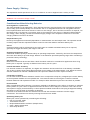
Power Supply Modules
Lithium Ion /Polymer Module T24-BC1
The T24-BC1 is a battery charger and power supply suitable for the T24 range of 3V acquisition modules. The
T24 Battery Charger is designed to supply a constant 3.3V from a Li-ion Battery while also charging the battery
from an input voltage. The unit comes pre-configured to provide a charging current of 466mA suitable for
VARTA LIP653450. This module also supports additional batteries providing a charge current of 133mA via the
removal of the leaded resistor (non surface mount).
23
Mantracourt Electronics Limited T24-RA User Manual
Physical Connections
Charging Current
Resistor Fitted
Resistor Removed
466mA
133mA
GND
Battery +
Voltage Out
GND
Voltage Supply
GND
LED lights when supply voltage applied
Specification
Parameter
Min
Typ
Max
Units
Supply Voltage
Regulated Voltage Output
Battery positive connection
Maximum Cable Length
Quiescent Current
4.1
-
5
3.3
3.7
6
150
V
V
V
mm
μA
1.7
Note LED will only be lit when an input voltage is applied
Suitable Batteries
VARTA LIP653450
Rated Capacity: 1100mAh
Dimensions: 35 x 54 x 7 (mm)
Weight: 20g
Charge Time : 3 Hours @ 466mA
Battery life = 1 month 25 days*
VARTA LIC18650
Rated Capacity: 2200mAh
Dimensions: 18.25 Diameter 65mm Height
Weight: 46g
Charge Time : 4.5 Hours @ 466mA
Battery life = 3 months 20 days*
UBC 581730
Rated Capacity: 250mAh
Dimensions: 18 x 31.5 x 5.8 (mm)
Weight: 6.5g
Charge Time : 2 Hours @ 133mA
Battery life = 12 days 13 hours*
* Note: Battery life is calculated with a T24-RA running in low power mode with a sample time of 5mS and transmit interval of 333mS
and an input impedance of 1000 Ohms for 2 hours out of every 8 hours.
Mantracourt Electronics Limited T24-RA User Manual
24
Capacitor Module T24-BC2
This is used for batteries which have an internal resistance of greater than 150mOhms overcoming voltage
drops during high current phases of the low power mode cycle.
This problem becomes apparent when attempting to communicate with high peak current acquisition modules
such as a T24-PA using the T24 Toolkit or power cycling when the battery is near the end of its life. In normal
operation (Low power mode) with a handheld T24-HS where the T24-PA is connected to an uninterrupted
battery this module is generally not required.
Using lower impedance strain gauges (or multiple parallel strain gauges) exacerbates this problem.
Consult Sales for details. Alternatively fit an electrolytic capacitor across battery of 2000uF or greater. This
capacitor should be of low ESR (< 70mOhms).
25
Mantracourt Electronics Limited T24-RA User Manual
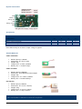
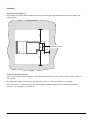
Mounting
Mechanical size
16.8 mm
16.0 mm
37.5 mm
29.8 mm
2.15 mm
8.42 mm
O 2.1 mm
4.80 mm
32.12 mm
There are two holes available for mounting. The one nearest the connection pads can accept an M2 screw or
American equivalent #0-80. Important Note: DO NOT USE #2 screw size. Note that the mounting hole is
connected directly to the Battery ground of the acquisition module.
The mounting hole near the chip antenna cannot accept metal mounting hardware.
The connection holes are on a 1.9mm pitch and are a diameter of 1mm.
Mantracourt Electronics Limited T24-RA User Manual
26
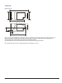
Antenna
Internal Chip Antenna
20 mm
There must be no metal objects within 7mm of the antennas long edge and 20mm from the short edges. See
diagram below
Internal Antenna
20 mm
7 mm
External Antenna Option
Use of a T24 external antenna requires a T24 acquisition module with a UFL connector stud in place of the onpcb antenna.
T24 acquisition modules fitted with a UFL stud have a suffix ‘e’ to the part number e.g. T24-SAe
Note: The suffix ‘e’ is omitted where the T24 acquisition module is fitted inside a T24-ACM or T24-ACMi
enclosure e.g. T24-ACM-SA, T24-ACMi SA
27
Mantracourt Electronics Limited T24-RA User Manual
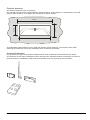
External Antennas
The external antennas come in two styles.
The flat PCB antenna can be mounted inside a plastic housing or to the outside of a metal housing. The PCB
requires 3mm Clearance on all edges, this also applies to the RF window.
26 mm
20 mm
64 mm
58 mm
The bulkhead mounting antenna can be used with metal or plastic housings. Care must be taken when
mounting the Antenna to ensure the installation does not become directional.
Antenna Orientation
For the maximum range the acquisition module and any other modules should be orientated as shown.
The sensitivity to the radio transmission will be reduced if the acquisition module is oriented in a vertical or
portrait position if a handheld is used because the handheld can only be used in one orientation.
Mantracourt Electronics Limited T24-RA User Manual
28
Specifications
General Radio
Min
License
Modulation method
Radio type
Data rate
Radio Frequency
Power
Range RAD24i (Integrated antenna)
Range RAD24e (External antenna)
Channels (DSSS)
Typical
License Exempt
MS (QPSK)
Transceiver (2 way)
250
Max
2.4000
2.4835
1
100 (325)
200 (650)
Units
K bits/sec
GHz
mw
Metres (feet) *
Metres (feet) *
16
* Maximum range achieved in open field site at a height of 3 metres above ground.
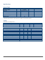
T24-RA
Specification at 3V supply at 25°C
Measurement
Sensor Excitation Voltage
Input Range
Accuracy
Min
2.4
500
Electrical
Power Supply voltage
Power Supply ripple
Min
2.1
Typical
3.0
Max
3.6
50
Units
V DC
mV AC pk-pk
Power Supply current
Normal Mode
Standby / Low power mode
Min
Typical
35
5
Max
65
40
Units
mA
uA
Environmental
Operating temperature range
Storage temperature
Humidity
Min
-40
-40
0
Typical
Max
+85
+85
95
Units
°C
°C
%RH
Physical
PCB Dimensions
29
Mantracourt Electronics Limited T24-RA User Manual
Typical
2.5
Max
2.6
100,000
0.01
16.8 x 37.5 x 6.5mm
Units
VDC
Ohms
% of Full Scale
Approvals
CE
Complies with EMC directive. 2004/108/EC
The Radio Equipment and Telecommunications Terminal Equipment (R&TTE) Directive,
1999/5/EC,
European Community, Switzerland, Norway, Iceland, and Liechtenstein
English:
This equipment is in compliance with the essential requirements and other
relevant provisions of Directive 1999/5/EC.
Deutsch:
Dieses Gerät entspricht den grundlegenden Anforderungen und den weiteren
entsprecheneden Vorgaben der Richtlinie 1999/5/EU.
Dansk:
Dette udstyr er i overensstemmelse med de væsentlige krav og andre relevante
bestemmelser i Directiv 1999/5/EF.
Español:
Este equipo cumple con los requisitos esenciales asi como con otras
disposiciones de la Directive 1999/5/EC.
Français:
Cet appareil est conforme aux exigencies essentialles et aux autres dispositions
pertinantes de la Directive 1999/5/EC.
Íslenska:
Þessi búnaður samrýmist lögboðnum kröfum og öðrum ákvæðum tilskipunar
1999/5/ESB.
Italiano:
Questo apparato é conforme ai requisiti essenziali ed agli altri principi sanciti
dalla Direttiva 1999/5/EC.
Nederlands: Deze apparatuur voldoet aan de belangrijkste eisen en andere voorzieningen
van richtlijn 1999/5/EC.
Norsk:
Dette utstyret er i samsvar med de grunnleggende krav og andre relevante
bestemmelser i EU-directiv 1999/5/EC.
Português:
Este equipamento satisfaz os requisitos essenciais e outras provisões da
Directiva 1999/5/EC.
Suomalainen: Tämä laite täyttää direktiivin 1999/5/EY oleelliset vaatimukset ja on siinä
asetettujen muidenkin ehtojen mukainen.
Svenska:
Denna utrustning är i överensstämmelse med de väsentliga kraven och andra
relevanta bestämmelser i Direktiv 1999/5/EC.
This equipment is in compliance with the essential requirements and other relevant provisions of Directive
1999/5/EC.
FCC
Family: RAD24
Models: i and e for internal and external antenna variants. For antenna T24-ANTA and T24-ANTB
FCC ID:VHARAD24
This device complies with Part 15c of the FCC Rules. Operation is subject to the following two conditions: (1) this
device may not cause harmful interference, and (2) this device must accept any interference received, including
interference that may cause undesired operation.
CAUTION: If the device is changed or modified without permission from Mantracourt Electronics Ltd, the user
may void his or her authority to operate the equipment.
Mantracourt Electronics Limited T24-RA User Manual
30
Industry Canada
Models: i and e for internal and external antenna variants. For antenna T24-ANTA and T24-ANTB
IC:7224A-RAD24
This apparatus complies with RSS-210 - Low-power Licence-exempt Radiocommunication Devices (All Frequency
Bands): Category I Equipment RSS.
OEM / Reseller Marking and Documentation Requirements
FCC
The Original Equipment Manufacturer (OEM) must ensure that FCC labelling requirements are met. This
includes a clearly visible label on the outside of the final product enclosure that displays the contents as
shown:
Contains FCC ID:VHARAD24
This device complies with Part 15 of the FCC Rules. Operation is subject to the following two conditions:
(1) this device may not cause harmful interference and
(2) this device must accept any interference received, including interference that may cause undesired operation.
The acquisition modules have been tested with T24-ANTA and T24-ANTB. When integrated in OEM products,
fixed antennas require installation preventing end-users from replacing them with non-approved antennas.
Antennas other than T24-ANTA and T24-ANTB must be tested to comply with FCC Section 15.203 (unique
antenna connectors) and Section 15.247 (emissions).
Acquisition modules have been certified by the FCC for use with other products without any further
certification (as per FCC section 2.1091). Changes or modifications not expressly approved by Mantracourt
could void the user’s authority to operate the equipment.
In order to fulfil the certification requirements, the OEM must comply with FCC regulations:
1. The system integrator must ensure that the text on the external label provided with this device is placed on
the outside of the final product.
2. The acquisition modules with external antennas may be used only with Approved Antennas that have been
tested by mantracourt.
IC
Labelling requirements for Industry Canada are similar to those of the FCC. A clearly visible label on the
outside of the final product enclosure must display the following text:
Contains Model RAD24 Radio (2.4 GHz), IC:7224A-RAD24
Integrator is responsible for its product to comply with RSS-210 - Low-power Licence-exempt
Radiocommunication Devices (All Frequency Bands): Category I Equipment RSS.
CE
The T24 series has been certified for several European countries.
If the acquisition module is incorporated into a product, the manufacturer must ensure compliance of the final
product to the European harmonized EMC and low-voltage/safety standards. A Declaration of Conformity must
be issued for each of these standards and kept on file as described in Annex II of the R&TTE Directive.
Furthermore, the manufacturer must maintain a copy of the T24 device user manual documentation and ensure
the final product does not exceed the specified power ratings, antenna specifications, and/or installation
requirements as specified in the user manual. If any of these specifications are exceeded in the final product, a
submission must be made to a notified body for compliance testing to all required standards.
OEM Labelling Requirements
The ‘CE’ marking must be affixed to a visible location on the OEM product.
31
Mantracourt Electronics Limited T24-RA User Manual
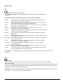
The CE mark shall consist of the initials “CE” taking the following form:
If the CE marking is reduced or enlarged, the proportions given in the above graduated drawing must be
respected.
The CE marking must have a height of at least 5mm except where this is not possible on account of the
nature of the apparatus.
The CE marking must be affixed visibly, legibly, and indelibly.
Mantracourt Electronics Limited T24-RA User Manual
32
Declaration Of Conformity
We, Mantracourt Electronics Limited
The Drive
Farringdon
Exeter
Devon EX5 2JB
declare under our sole responsibility that our products in the T24 Radio Telemetry Product Range to which
this declaration relates are in conformity with the appropriate standard EN 300 328 following the provisions of
the Radio and Telecommunications Terminal Equipment Directive 1999/5/EC, FCC CFR Title 47 part 15c BS EN
61000-4-2 and BS EN 61000-4-3 following the provisions of the EMC Directive 2004/108/EC and Low Voltage
Directive 2006/95/EC.
December 2007
Brett James
Development Manager
Mantracourt Electronics Limited.
33
Mantracourt Electronics Limited T24-RA User Manual
FCC ID:VHARAD24
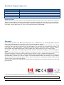
Worldwide Regional Approvals
Region
Europe
USA
Canada
Australia
China
Japan
Product Conforms To
CE
FCC
IC
To Be Determined
To Be Determined
To Be Determined
Important Note
Mantracourt does not list the entire set of standards that must be met for each country. Mantracourt customers
assume full responsibility for learning and meeting the required guidelines for each country in their distribution
market. For more information relating to European compliance of an OEM product incorporating the T24 range
of modules, contact Mantracourt, or refer to the following web site: www.ero.dk
Warranty
All Telemetry products from Mantracourt Electronics Ltd., ('Mantracourt') are warranted against defective
material and workmanship for a period of (1) one year from the date of dispatch.
If the 'Mantracourt' product you purchase appears to have a defect in material or workmanship or fails during
normal use within the period, please contact your Distributor, who will assist you in resolving the problem. If it
is necessary to return the product to 'Mantracourt' please include a note stating name, company, address,
phone number and a detailed description of the problem. Also, please indicate if it is a warranty repair.
The sender is responsible for shipping charges, freight insurance and proper packaging to prevent breakage in
transit.
'Mantracourt' warranty does not apply to defects resulting from action of the buyer such as mishandling,
improper interfacing, operation outside of design limits, improper repair or unauthorised modification.
No other warranties are expressed or implied. 'Mantracourt' specifically disclaims any implied warranties of
merchantability or fitness for a specific purpose. The remedies outlined above are the buyer’s only remedies.
'Mantracourt' will not be liable for direct, indirect, special, incidental or consequential damages whether based
on the contract, tort or other legal theory.
Any corrective maintenance required after the warranty period should be performed by 'Mantracourt' approved
personnel only.
In the interests of continued product development, Mantracourt Electronics Limited reserves the right to alter product specifications without prior notice.
Code No. 517-930
Mantracourt Electronics Limited T24-RA User Manual
Issue 1.3
27.10.14
34
Distribuidor
Brasil e América do Sul
C O N TA T O
Ender eço
Rua Sete de Setembro, 2671 - C entro
13560-181 - São C arlos - SP - Brasil
Telefone
+ 55 (16) 3371-0112
Metrolog Controles de Medição
Fax
+ 55 (16) 3372-7800
Inter net
www.metrolog.net
metrolog @metrolog.net
www.metrolog.net / mantracourt.com
[email protected]
tel +55 (16) 3371-0112