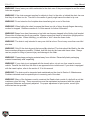
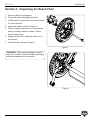
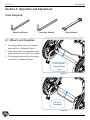
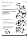
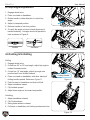
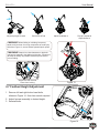
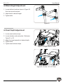
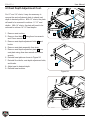
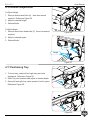
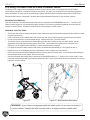
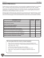
1
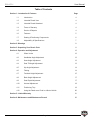
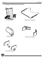
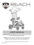
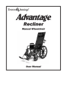
REACH
USER MANUAL
CHAIR PROVIDER: THIS MANUAL MUST BE GIVEN TO THE USER OF
THIS DEPENDENT MOBILITY BASE
USER: READ THIS MANUAL BEFORE USING THIS DEPENDENT
MOBILITY BASE AND SAVE FOR FUTURE REFERENCE
Product delivered may vary from the one described and pictured in this manual.
Revision 15-0729
User Manual
REACH
Authorized Leggero Provider:
Provider Name
Address
Phone
Email
Website
Page 2
User Manual
REACH
Table of Contents
Section 1: Introduction & Features
Page
1.1
Introduction
4
1.2
Intended Reach User
4
1.3
Intended Reach Attendant
4
1.4
Terms of Warranty
4
1.5
Service & Repairs
4
1.6
Features
5
1.7
Seating & Positioning Components
6
1.8
Adjustability & Speciications
7
Section 2: Warnings
8
Section 3: Unpacking Your Reach Chair
11
Section 4: Operation and Adjustment
12
4.1
Wheel Locks
12
4.2
Handlebar Angle Adjustment
13
4.3
Knee Angle Adjustment
13
4.4
Seat Tilt Angle Adjustment
13
4.5
Hip Angle Adjustment
14
4.6
Folding
14
4.7
Footbed Height Adjustment
15
4.8
Back Height Adjustment
17
4.9
Seat Depth Adjustment
17
4.10
Armrest Adjustment
19
4.11
Positioning Tray
19
4.12
Using the Reach as a Chair in a Motor Vehicle
20
Section 5: Limited Warranty
21
Section 6: Maintenance and Maintenance Record
22
Page 3
User Manual
REACH
Section 1: Introduction, Warnings, & Features
1.1 Introduction
Thank you for selecting the Reach chair. This manual explains how to operate, adjust, and
maintain your Reach chair. The product as described is subject to technical alterations without
notice.
We are sorry that we cannot offer this user information in a format, appropriate for use by
visually impaired people. The visually Impaired must contact an authorized Leggero provider to
obtain information and instruction in the form of verbal communication and hands on training if
necessary.
1.2 Intended Reach User
Rehab pushchairs and pediatric positioning systems are appropriate for children who are limited
to a seated position and require mobility and positioning assistance. Individuals who need such
assistance can have a wide variety of diagnosis limiting their ability to achieve mobility without
such a system. For maximum occupancy rating and additional speciications, reference section
1.7 of this manual.
1.3 Intended Reach Attendant
Attendants who operate the chair must be visually, mentally, and physically capable of safely
operating the chair under all circumstances. Attendants must read and follow all instructions
provided in this manual.
1.4 Terms of Warranty
Warranty applies only when the product is used in concordance with the manufacturer’s
recommendations and for the intended purposes and speciied conditions of the product.
1.5 Service and Repairs
Service and repair of the Reach chair should be performed only by Leggero authorized
providers. Should any problems arise, please contact the provider that supplied the chair.
Authorized providers only replace and install original Leggero spare parts.
Page 4
User Manual
REACH
1.6 Features
Sun & Weather Shade
Adjustable Height Back
Armrests/Tray Receivers
Adjustable Height
Footbed
Handlebar Angle
Adjustment
Adjustable Depth Seat
Quick Release
Rear Wheels
Folding
Handle
Serial Number Label
Wheel Lock Lever
Page 5
User Manual
REACH
1.7 Seating & Positioning Components
LT Back Cushion
Therapeutic Positioning Tray
Headrest Options
Lateral Thoracic Supports
Lateral Pelvic Supports
Page 6
User Manual
REACH
1.8 Adjustability and Speciications
Adjustability
Reach 12
Reach 14
Reach 16
Seat Depth
8-13” (20-33cm)
11-16” (28-40cm)
13-18” (33-46cm)
Seat Width
12” (30cm)
14” (35cm)
16” (40cm)
Seat to Fooplate
8-13” (20-33cm)
11-16” (28-40cm)
13-18” (33-46cm)
Max Back Height
18” (46cm)
21” (53cm)
24” (61cm)
Hip Angle Adjustment
85-115°
85-105°
85-95°
Seat Angle
10°, 20°, or 30°
10°, 20°, or 30°
10°, 20°, or 30°
Speciications
Reach 12
Reach 14
Reach 16
Maximum User Weight
80lb (36kg)
110lb (50kg)
150lb (68kg)
Mobility Base Weight
27lb (12kg)
29lb (13kg)
31lb (14kg)
Overall Width
21.5” (55cm)
23.5” (60cm)
25.5” (65cm)
Front Tire Diameter
7” (18cm)
7” (18cm)
7” (18cm)
Rear Tire Diameter
16” (40cm)
16” (40cm)
16” (40cm)
Folded Dimensions
31 x 21.5 x 18”
(79 x 55 x 46cm)
31 x 23.5 x 18”
(79 x 60 x 46cm)
33 x 25.5 x 18”
(84 x 65 x 46cm)
Maximum Safe Slope
5°
5°
5°
Page 7
User Manual
REACH
Section 2: Warnings
Read this Manual Completely Before Using
All caregivers and/or attendants must read this user manual prior to operating the Reach chair.
Familiarize yourself with the handling and functions of the product prior to actual use. If there is
any information in this manual that you do not understand, please contact your authorized Leggero
provider for assistance.
Failure to follow instructions or comply with warnings within this manual could result in
personal injury and/or damage to the Reach chair, potentially voiding the warranty.
Symbols Used on Product Warning Labels and in User Manual
WARNING!
The word “WARNING” or this symbol indicate practices that are unsafe or
dangerous and could result in serious injury to the occupant and/or caregiver.
WARNING! READ INSTRUCTION MANUAL
Choose The Right Chair & Safety Options
In the mobility industry, there are several options available to meet the needs of children. Make
sure that your (and your provider’s) choice of chair and other options takes into account your child’s
comfort, positioning, physical limitations, and hazards that may be encountered during daily use.
Page 8
User Manual
REACH
Warnings: Failure to Follow These Warnings Could Result in
Serious Injury or Death
WARNING! All caregivers and/or attendants must read this user manual prior to operating the Reach
chair. Familiarize yourself with handling and functions of the product prior to actual use. If there is
any information in this manual that you do not understand, please contact your authorized Leggero
provider for assistance.
WARNING! Non-conventional use and/or handling of the product can be dangerous. The pushchair
is not safely suitable for skating or similar high speed activities. Swiveling front wheels can wobble
at higher speed and can cause a sudden stop and tip over of the chair. For maximum safety use the
pushchair only at regular walking speed. Under no circumstance should you let go of the handlebar
while pushing. Do not ever push the chair away.
WARNING! The initial set up of this pushchair must be performed by a qualiied technician.
WARNING! Procedures other than those described in this manual must be performed by a qualiied
technician.
WARNING! The weight carried by the Reach chair must not exceed the total weight limit of 80lb/36kg
for 12” chairs, 110lb/50kg for 14” chairs, or 150lb/68kg for 16” chairs (Maximum occupant weight plus
weight of accessories and/or items carried.)
WARNING! Adjustments made to the chair may affect stability, increasing the risk of tipping.
Adjustments must be made by your authorized Leggero provider.
WARNING! Avoid getting the chair wet or storing the chair in damp environments. Excess moisture
can cause rust or corrosion, which can result in component failure. If the chair is exposed to moisture,
dry thoroughly.
WARNING! Do not leave the chair or child in the sun or near other heat sources since the surfaces on
the chair may reach temperatures capable of burning the child. Do not leave the chair or child outside
in cold temperatures because contact with a chair in temperatures below freezing could result in injury.
Damage to the chair may also result from exposure to extreme hot or cold temperatures.
WARNING! The chair should only be used on solid and level ground. Do not attempt to push
the chair over or into obstacles. Always remove the child from the chair when lifting chair to clear
obstacles.
WARNING! Do not use the chair on slopes steeper than 5 degrees. Do not leave the chair parked on
a slope or an incline. Pay particular attention when on slopes and inclines to prevent the child from
falling out of the chair, the chair from tipping over, or the chair from rolling away.
WARNING! Before leaving the chair and before getting into and out of it, always engage the wheel
locks. Do not use the wheel locks to stop the chair while moving.
Page 9
User Manual
REACH
WARNING! Never leave your child unattended in the chair even if they are strapped in and the wheel
locks are engaged.
WARNING! If the chair occupant reaches for objects in front, to the side, or behind the chair, be sure
that they do not lean too far. The shift in the center of gravity might cause the chair to tip over.
WARNING! Do not stand on the footplate when transferring into or out of the chair.
WARNING! When folding the chair, be aware that there is a risk of injury through ingers becoming
crushed or trapped. Reference section 4.6 of this manual for further information.
WARNING! Straps from chest harnesses or lap belts can become trapped in the folding lock bracket.
Please trim all straps as shortly as possible. Always ensure that frame is locked into upright position
prior to resuming use. When unfolding, you will hear a “click” when the frame locks.
WARNING! The chair is only intended to carry one child at a time. Do not carry more than one child
at a time.
WARNING! Only lift the chair by parts that are solidly attached. The chair should be lifted by the side
frame members whenever possible. If folded, hold the chair by the lower side frame tubes. Always
use two people for lifting to prevent injury and damage to the chair.
WARNING! Please keep packaging material away from children. Discard all plastic packaging
material immediately after unpacking.
WARNING! If your chair is not equipped with the transit option, do not use it as a seat in a motor
vehicle. Transfer the child from the chair to an approved motor vehicle seat. If your chair is equipped
with the transit option, refer to the section 4.12 in this manual.
WARNING! The chair must be inspected and maintained per the chart in Section 6: Maintenance.
Problems detected must be repaired prior to resuming use of the chair.
WARNING! Many of the fasteners used to construct the Reach chair consist of a bolt with a nut that
contains a nylon lock ring. These connections must be maintained and secured with the original
equipment fasteners and properly adjusted. For proper adjustment of pivot points, consult your
authorized service provider.
Page 10
User Manual
REACH
Section 3: Unpacking the Reach Chair
1. Remove chair from packaging.
2. Discard all plastic packaging materials.
3. Unfold frame and seat back, reference Section
4.6 of this manual.
4. Install rear wheels, reference Figure 1.
5. Check for proper adjustment of quick release
axles by pulling outward on wheel. Wheel
should hold in place.
6. Engage wheel locks, reference section 4.1 of
this manual.
7. Install anti-tips, reference Figure 2
Figure 1
WARNING! Please keep packaging material
away from children. Discard all plastic packaging
material immediately after unpacking.
Figure 2
Page 11
User Manual
REACH
Section 4: Operation and Adjustment
Tools Required:
4mm Hex Wrench
5mm Hex Wrench
13mm Wrench
4.1 Wheel Lock Operation
1. To engage wheel locks, push crossbar
down with foot. Reference Figure 3.
2. Verify wheel locks are engaged on each
side by trying to move chair front to back.
3. To disengage wheel locks, pull crossbar
up with foot. Reference Figure 4.
Push DownTo
Engage Wheel
Lock
Figure 3
Pull Up To
Disengage
Figure 4
Page 12
User Manual
REACH
4.2 Handlebar Angle Adjustment
1. Press and hold buttons on outside of each
adjustment ratchet, reference Figure 5.
2. Adjust handlebar to desired angle.
3. Release buttons.
Figure 5
4.3 Knee Angle Adjustment
1. Press and hold buttons on outside of each adjustment
ratchet, reference Figure 6.
2. Adjust knees to desired angle.
3. Release buttons.
Figure 6
4.4 Seat Tilt Angle Adjusment
1. Engage Wheel Locks.
2. Remove bolt and nut from left and right sides,
reference Figure 7. 5mm hex wrench and 13mm
wrench required.
3. Adjust seat to desired angle, reference Figure 8.
4. Install bolts and nuts, tighten. Do not over-torque,
this could result in damage to the seat tube.
5. Adjust hip angle to desired angle, reference
section 4.5.
Figure 7
10°
20°
30°
Figure 8
Nut
Page 13
User Manual
REACH
4.5 Hip Angle Adjustment
1. Engage wheel locks.
2. Place one hand on handlebar.
3. Rotate handle in either direction to unlock hip
angle.
4. Adjust to despired position.
5. Release handle to lock into position.
6. To verify hip angle is locked, check alignment of
handle assembly. Linkages should be parallel to
tube as shown in Figure 9.
Locked
Figure 9, Locked
Unlocked
Figure 10, Unlocked
4.6 Folding & Unfolding
Folding
1. Engage wheel locks.
2. If chair has 20° or 30° seat angle, adjust hip angle to
furthest forward postion.
3. If chair has 10° seat angle, adjust hip angle one
position back from furthest forward.
4. Place one hand on handlebar, with other hand pull
folding handle upward. Reference Figure 11.
5. Push forward on handlebar and chair will fold.
6. Adjust handlebar inward.
7. Flip footbed upward.
8. Adjust knee angle as far inward as possible.
Folding Handle
Figure 11
Unfolding
1. Adjust handlebar outward.
2. Flip Footbed down.
3. Swing knee ratchets outward.
4. Pull back on handlebar until locking mechanism locks
Figure 12
Page 14
User Manual
REACH
Adjust Hip Angle Forward
Pull Handle & Fold
Flip Up Footplate &
Adjust Knees In
Adjust Handlebar In
WARNING! When folding or unfolding, keep arms,
hands, and feet clear of moving components to avoid injury.
Reference Figure 13, arrows indicate potential pinch points.
WARNING! Straps from chest harnesses or lap belts
can become trapped in the folding lock bracket. Please trim
all straps as shortly as possible & attach lap belt buckles
prior to folding.
Straps Here Can Prevent
Frame from Locking
Figure 13
4.7 Footbed Height Adjustment
1. Remove left and right button head bolts,
reference Figure 14. 5mm hex wrench required.
2. Adjust footrest assembly to desired height.
3. Reinstall bolts.
Figure 14
Page 15
User Manual
REACH
4.7 Footbed Height Adjustment Cont.
If your footbed is currently conigured as shown in Figure
14, it may be necessary to adjust the footbed assembly
downward on the footrest extensions (12” & 14” chairs only).
1. Remove bolts as described in previous
section.
2. Remove footbed assembly from chair.
3. Remove lat head and button head
bolts from left and right sides, reference
Figure 16. 5mm Hex wrench required.
4. Reinstall bolts in lowest position on
footbed extensions as shown in Figure
17.
5. Reinstall footbed assembly and adjust
to desired height.
Figure 15
Figure 16
For 12” units, it will be necessary to change the
footbed extensions to obtain leg drops beyond
11in./28cm. Longer extensions were supplied
with your chair, but if you do not have them please
contact your authorized provider.
1. Remove bolts as described in previous section.
Reference Figure 18.
2. Install longer extensions as shown in Figure 19.
For the next leg drop position beyond what was
achievable with shorter extensions, install lat
head bolts through 7th hole from top of footbed
extensions.
3. Install footbed assembly in chair and adjust to
desired height
Figure 17
Short Extensions
Figure 18
7th Hole
Long Extensions
Figure 19
Page 16
User Manual
REACH
4.8 Back Height Adjustment
1. Loosen bolts at locations shown in Figure 20.
5mm hex wrench required.
2. Adjust back to desired height.
3. Tighten bolts.
Figure 20
4.9 Seat Depth Adjustment
1. Loosen seat cushion straps.
2. Loosen knob(s) under seat plate. Reference
Figure 21 or 22.
3. Adjust front seat assembly to desired depth.
4. Tighten knob.
5. Tighten seat cushions straps.
Figure 21, Single Knob 12” Chair
Figure 22, 2 knobs 14” & 16” Chair
Page 17
User Manual
REACH
4.9 Seat Depth Adjustment Cont.
2
For 12” and 14” chairs, it may be necessary to
remove the seat adjustment plate to extend seat
depth to desired position. With 12” chairs, the plate
will need to be removed to achieve 11”-13” seat
depths. With 14” chairs, the plate will need to be
removed to achieve 14”-16” seat depths.
1. Remove seat cushion.
2. Remove front bolts 1 using 4mm hex wrench
and 10mm wrench.
3. Remove seat depth adjustment bolts 2 and
knobs.
4. Remove seat plate assembly from chair.
5. Remove seat depth adjustment plate 3 from
seat plate using 4mm hex wrench and 10mm
wrench.
6. Reinstall seat plate as shown in Figure 24.
7. Reinstall front bolts, seat depth adjustment bolts,
and knobs.
8. Adjust seat to desired depth.
9. Reinstall seat cushion.
1
Figure 23
3
Figure 24
Figure 25
Page 18
User Manual
REACH
4.10 Armrest Adjustment
To Adjust Height:
1. Remove button head bolts (4). 4mm hex wrench
required. Reference Figure 26.
2. Adjust to desired height.
3. Reinstall bolts.
To Adjust Angle:
1. Remove rear button head bolts (2). 4mm hex wrench
required.
2. Adjust to desired angle.
3. Reinstall bolts.
Figure 26
Angle
Height
Figure 27
4.11 Positioning Tray
1. To insert tray, swing left and right tray cam locks
downward. Reference Figure 28.
2. Slide Tray into receivers and adjust to desired depth.
3. Swing left and right tray cams upward to lock in place.
Reference Figure 29.
Figure 28
Figure 29
Page 19
User Manual
REACH
4.12 Using The Reach Chair As A Seat In A Motor Vehicle
The Reach Chair is approved for transporting children in motor vehicles when it is equipped with the OPTIONAL
transit feature and used in accordance with these instructions. The chair must be secured in a forward-facing position
with a Wheelchair Tie-down and Occupant Restraint System (WTORS) which meets the requirements of SAE J2249
Recommended Practice—Wheelchair Tie-down and Occupant Restraint Systems For Use in Motor Vehicles.
IMPORTANT INFORMATION:
This chair conforms to and has been dynamically tested in compliance with ANSI/RESNA WC/Vol. 1 – Section 19.5.3.
Please contact Leggero or your authorized Leggero provider if you have any questions regarding use of the chair for
seating in a motor vehicle. Contact information can be found on page 2 of this manual.
WARNINGS & INSTRUCTIONS:
• The Reach chair must be used as indicated in these instructions and the instructions supplied by the vehicle mounted
tie-down manufacturer.
• Chair occupant should be transferred to the vehicle seat and use the vehicle restraint system whenever possible.
• Do not exceed maximum occupant weight ratings. Reference Section 1.8 of this manual.
• The Reach Chair must be placed in a forward-facing position when used as a seat in a motor vehicle. Use an
approved 4-point strap-type tie-down system for the chair. Use an approved 3-point belt for occupants over
50lb/23kg. For occupants under 50lb/23kg, a 5-point transit harness is required.
• For approved transit tie-down locations and location of belt/harness attachment pin, see Figures 30 and 31.
• Restraints must not be held away from the child’s body by chair components or accessories.
• Belt or harness straps should be adjusted until they are snug and do not have slack. If you can pinch the webbing of
the belt straps between your ingers, then it is too loose.
• Only belt restraints that comply with the provisions of ANSI/RESNA WC/Vol. 1 – Section 19 4.9.2-4.9.5 and 5.2 that
have been dynamically tested in accordance with Annex A & 5.3 of the same, should be used on the chair for use as a
restraint in a motor vehicle.
Figure 30
Figure 31, Belt/Harness Attachment
WARNING! If your chair is not equipped with the transit option, do not use it as a seat in
a motor vehicle. Transfer the child from the chair to an approved motor vehicle seat.
Page 20
User Manual
REACH
Section 5: Limited Warranty
A. THIS WARRANTY IS EXTENDED ONLY TO THE ORIGINAL PURCHASER OF OUR PRODUCTS.
B. FOR LIFETIME
Leggero LLC warrants the frame and quick-release axles of this chair against defects in materials and
workmanship for the life of the original purchaser. The expected life of this frame is ive years.
C. FOR ONE (1) YEAR
We warrant all original equipment parts and components of this chair against defects in materials and
workmanship for one year from the date of the irst consumer purchase.
D. LIMITATIONS
1. We do not warrant:
• Tires, tubes, upholstery, push handle grips, or armpads.
• Damage resulting from neglect, misuse, or from improper installation or repair.
• Damage resulting from transit use.
• Damage from exceeding the weight limit indicated on the serial number label.
2. This warranty is valid only when the product is used according to the speciied conditions and the
intended purposes, following all manufacturer recommendations. It is void otherwise.
3. This warranty shall not apply to problems arising from normal wear, and such evaluation will be solely
determined by Leggero LLC.
4. This warranty is void if the product is modiied without Leggero’s express written consent including, but
not limited to, modiication through the use of unauthorized parts or attachments; products damaged by
reason of repairs made to any component without speciic consent of Leggero; or to a product damaged
by circumstances beyond Leggero’s control, and such evaluation will be solely determined by Leggero.
5. This warranty is void if the original serial number is removed or altered.
6. This warranty applies in the USA only. Check with your supplier if international warranties apply.
E. WHAT MANUFACTURER WILL DO
Our sole liability is to repair or replace covered parts. This is the exclusive remedy for consequential
damages.
F. WHAT YOU MUST DO
1. Obtain from us, while this warranty is in effect, prior approval for return or repair of covered parts.
2. Return the product or part(s), freight pre-paid to Leggero LLC. Contact Leggero customer service at
1-844-503-KIDS for a return address and to obtain a return authorization number (RA#).
3. Pay the cost of labor to repair, remove or install parts.
G. NOTICE TO CONSUMER
1. If allowed by law, this warranty is in place of any other warranty, written or oral, express or implied,
including a warranty of merchantability, or itness for a particular purpose.
2. This warranty gives you certain legal rights. You may also have other rights that vary from state to state.
Page 21
User Manual
REACH
Section 6: Maintenance
Please consult your authorized provider if you have questions regarding maintenance of your Reach
chair. Consistent and thorough maintenance will extend the useful life of your chair. Improper
maintenance can signiicantly decrease the useful life of the chair. Any damaged parts should be
replaced prior to resuming use of the chair. The chair should be cleaned regularly and should be
serviced by an authorized dealer at least once per year.
Warranty might be affected if proper maintenance is not performed at the speciied intervals. Please
see table below for recomended maintenance procedures and frequency. There is a maintenance
record on the following page of this manual that should be used to document maintenance activities.
Maintenance Activity
Weekly
Monthly
P
Check wheels and tires for wear or damage
P
Check wheel lock function
Check for proper caster alignment
P
Verify that all fasteners are tight
P
Verify that quick release axles function properly
P
Check tilt lock mechanism for proper engagement
P
Check recline lock mechanism for proper engagement
P
Check all structural components for wear or damage
P
Check all accessory components for damage
P
We recommend that the chair be cleaned regularly:
•
•
•
•
•
Clean all frame components and plastic parts using mild detergents only.
Fabric parts may be washed. If using a washing machine, put them in a linen
bag or pillow case. Air dry.
In most cases, wiping with a damp cloth is suficient.
Do not use your chair in salt water as severe damage may result.
Keep sand or other particles from damaging the wheel and caster fork
bearings.
Page 22
User Manual
REACH
Maintenance Record
Date
Service
Provider
Technician
Description of Service
Page 23