1
ICE Emulator for 68HC11
TRACE32 Online Help
TRACE32 Directory
TRACE32 Index
TRACE32 Documents ......................................................................................................................
ICE In-Circuit Emulator .................................................................................................................
ICE Target Guides ......................................................................................................................
ICE Emulator for 68HC11 ........................................................................................................
1
WARNING ..............................................................................................................................
4
Quick Start ............................................................................................................................
5
Troubleshooting ...................................................................................................................
6
Hang-Up
6
Dualport Errors
6
FAQ ........................................................................................................................................
7
Basics ....................................................................................................................................
11
Emulation Modes
11
CPU Modes
13
SYStem.Clock
SYStem.Access
Clock generation
15
Dualport Modes
15
Code Sequencer
16
General SYStem Settings and Restrictions .......................................................................
General Restrictions
17
17
SYStem.Option Trace
Trace options
19
SYStem.Option PerReset
Reset target
19
SYStem.Option TestClock
Clock sense
19
RAM and register mapping
20
PLL mode
20
SYStem.Option BASE
SYStem.Option PLL
SYStem.Option RWMC
Memory strobe mode
20
SYStem.Option TRANS
Transparent mode
21
Strobe control
21
Exception Control ................................................................................................................
22
SYStem.Line EC
RESET Control
22
eXception.Activate
Force exception
23
eXception.Enable
Enable exception
24
eXception.Trigger
Trigger on exception
25
Stimulate exception
26
eXception.Pulse
©1989-2015 Lauterbach GmbH
ICE Emulator for 68HC11
1
EEPROM Management .........................................................................................................
27
Banked Target Systems .......................................................................................................
28
Internal
29
External
29
Memory Access Routines
31
MMU .......................................................................................................................................
Using the MMU for 68HC11K
32
32
SYStem.Option MMU
MMU usage
Using the MMU for 68HC11C
32
35
Memory Classes ...................................................................................................................
38
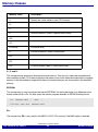
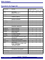
State Analyzer .......................................................................................................................
39
Keywords for the Trigger Unit
39
Keywords for the Display
40
Port Analyzer ........................................................................................................................
41
Keywords for the Port Analyzer
41
Additional Trace Channels
41
Modul M68HC11-A/E/D
42
Modul M68HC11-F
42
Compilers ..............................................................................................................................
43
3rd Party Tool Integrations ..................................................................................................
44
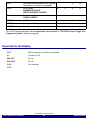
Realtime Operation Systems ...............................................................................................
45
Emulation Frequency ...........................................................................................................
46
Emulation Modules ..............................................................................................................
47
Module Overview
47
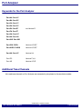
Order Information
48
Operation Voltage ................................................................................................................
49
Physical Dimensions ...........................................................................................................
50
Adapter ..................................................................................................................................
57
©1989-2015 Lauterbach GmbH
ICE Emulator for 68HC11
2
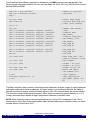
ICE Emulator for 68HC11
Version 06-Nov-2015
P:0069B0
\\IAR11\iar11\sieve+5
........... HLL
AI
E::w.d.l
addr/line source
register int i, primz, k;
int anzahl;
515
anzahl = 0;
517
for ( i = 0 ; i <= SIZE ; flags[ i++ ] = TRUE ) ;
; i <= SIZE ; i++ )
E::w.v.f /l /c
flags[ i ] )
end of frame
-001 main()
j = 15
{
primz = i + i + 3
sieve();
-000 sieve()
i = 3
primz = 3
k = 3
anzahl = 3
::w.per
imer
FORC 00 FOC1 L
FOC2
C1M 00 OC1M7 OffOC1M
C1D 00 OC1D7 L OC1D
CNT 32CD
IC1 FFFF
E::w.r
S
S
X
X
H
_
I
I
N
_
Z
Z
V
_
C
_
A
0
B
0
D
0
IX
3
IY
0
SP 240F
PC 69B0
CCR 0D4
SP >00
+01 00
+02 03
+03 00
+04 03
+05 00
+06 03
+07 00
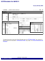
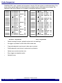
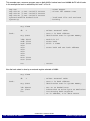
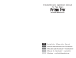
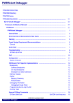
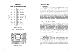
For general informations about the In-Circuit Debugger refer to the ”ICE User’s Guide” (ice_user.pdf). All
general commands are described in ”IDE Reference Guide” (ide_ref.pdf) and “General Commands and
Functions”.
©1989-2015 Lauterbach GmbH
ICE Emulator for 68HC11
3
WARNING
NOTE:
Do not connect or remove probe from target while target power is ON.
Power up:
Switch on emulator first, then target
Power down: Switch off target first, then emulator
©1989-2015 Lauterbach GmbH
ICE Emulator for 68HC11
4
WARNING
Quick Start
tbd.
©1989-2015 Lauterbach GmbH
ICE Emulator for 68HC11
5
Quick Start
Troubleshooting
Hang-Up
If you are not able to stop the emulation, there may be some typically reasons:
Clock Error
The clock lines between the target and the CPU on the probe are very short.
Therefore normally no problems should occur when using an external crystal.
Be sure that the capacitors on the target have a value of 20 pF minimum and
are with short routes connected to the CPU socket.
Dualport Errors
Dualport errors may occur by the following conditions:
1.
The operation frequency in GAP access mode is higher than 3 MHz.
2.
The clock signal is switched off.
3.
The CPU is hold in STOP state for a too long time.
To solve problems with dualport error first increase the SYStem.TimeReq value. Be sure that the
SYStem.TimeOut value is bigger than the access time limit. If it is not possible to solve the problem by
changing the values, you must switch to DENIED mode. In this mode no access to memory is possible while
running realtime emulation. The dualport access has no effect on CPU performance.
©1989-2015 Lauterbach GmbH
ICE Emulator for 68HC11
6
Troubleshooting
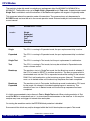
FAQ
Debugging via
VPN
The debugger is accessed via Internet/VPN and the performance is very
slow. What can be done to improve debug performance?
The main cause for bad debug performance via Internet or VPN are low data
throughput and high latency. The ways to improve performance by the debugger
are limited:
in practice scripts, use "SCREEN.OFF" at the beginning of the script and
"SCREEN.ON" at the end. "SCREEN.OFF" will turn off screen updates.
Please note that if your program stops (e.g. on error) without executing
"SCREEN.OFF", some windows will not be updated.
"SYStem.POLLING SLOW" will set a lower frequency for target state
checks (e.g. power, reset, jtag state). It will take longer for the debugger to
recognize that the core stopped on a breakpoint.
"SETUP.URATE 1.s" will set the default update frequency of Data.List/
Data.dump/Variable windows to 1 second (the slowest possible setting).
prevent unneeded memory accesses using "MAP.UPDATEONCE
[address-range]" for RAM and "MAP.CONST [address--range]" for ROM/
FLASH. Address ranged with "MAP.UPDATEONCE" will read the specified
address range only once after the core stopped at a breakpoint or manual
break. "MAP.CONST" will read the specified address range only once per
SYStem.Mode command (e.g. SYStem.Up).
©1989-2015 Lauterbach GmbH
ICE Emulator for 68HC11
7
FAQ
Target Power
Supply Switch
Is there a simple way to control target power supply via the ICE to prevent
problems after the ICE has been powered off?
Follow the sequence below.
If you own an output probe COUT8, connect it to the STROBE output connector.
Type PULSE2. and press F1. You will get the pin out of the output probe
COUT8. Pin 13 (OUT6) delivers +5 V after the emulator has finished its initialization and 0 V if the emulator is powered off. This can be used to drive
a relay via a transistor to switch the target power on and off automatically if
the Pulse Generator is not used for other purposes. The schematic of the
switching unit can be found in the file TARGETC.CMM.
Additionally Pin 13 (OUT6) can be controlled by ICE commands.
Target power supply off. "PULSE2.P +"
Target power supply on. "PULSE2.P -"
The following Practice command file creates 3 buttons in the Toolbox for:
Target power on
Target power off
Target power off and QUIT.
Adding that file to T32.cmm loads the buttons automatically after startup.
http://www.lauterbach.com/faq/targetc.cmm
Wrong
Location after
Break
Why is the location after break wrong?
Most emulators use some bytes of user stack for the break system. Therefore it
is necessary to have valid stack, if single step or breakpoints are used.
©1989-2015 Lauterbach GmbH
ICE Emulator for 68HC11
8
FAQ
CONFIG
Register
Cannot be
Modified
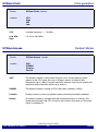
The CONFIG Register does not react on modifications.
The CONFIG Register is implemented with EEPROM cells. It can be written
anytime in any mode with the mechanism for programming EEPROM. Writing
has no immediate effect. The new value gets active with the next reset. See also
chapter 4.4.1.6 CONFIG Register Programming in M68HC11 E Series Technical
Data Book.
So, for changing the value use the following PRACTICE commands:
SYStem.Down
SYStem.CPU SingleTst
SYStem.Mode AloneInt
Data.Set EEPROM:103f value
SYStem.Down
SYStem.Mode AloneInt
Data.dump 103f
Then you can see the changed value.
©1989-2015 Lauterbach GmbH
ICE Emulator for 68HC11
9
FAQ
68HC11
Start-up
Problems
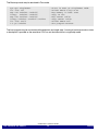
How can I program registers, which can be accessed through the first 64
CPU cycles only.
In TEST mode, the emulator can access all registers at any time. In EXPANDED
or SINGLE mode, the processor must run excecute a RESET. The following
example shows, how the eXception. Activate instruction can be used for
generating an immediate reset:
; setup operation modes
sys.res
sys.cpu expanded
sys.m ee
; disable EPROM
d.s 3f 04
; map memory
map.def 0--0ffff
; define reset vectors
d.s 0fffe %w 1000
d.s 0bffe %w 1000
; load sample program
d.a 1000--101f nop
d.a 1020 bra 1020
; example for option register programming
d.a 1010 ldaa #0
d.a ,
staa 39
; set 1st breakpoint, typically on 'main' in C program
b.s 1020 /p
; activate cpu reset
x.a cpureset on
; start emulation
g
; release cpu reset
x.a cpureset off
; check if o.k.
wait 0.1s
if n:state.run():a:r(pc)==1020
print "Startup o.k."
enddo
©1989-2015 Lauterbach GmbH
ICE Emulator for 68HC11
10
FAQ
Basics
The ICE-11 emulation head supports all 68HC11 derivatives from Freescale Semiconductor and Toshiba.
The adaption to different probes is done by changing the module. Modules support both DIL and PLCC
versions, where applicable. The maximum frequency of the base modul is 6 (24) MHz, however the
emulation is only possible to the max. speed of the MCU's available from the chip manufacturer. All
emulation probes support single chip and expanded modes. The probes for 68HC1-K/N/C may run with or
without MMU. The emulator supports either 1 MByte directly or 256 pages with 64 K each together with
banked target systems or paged EPROMs. An additional slot in the base modul offers upgrading with the
port analyzer to get timing and state trace features for all MCU I/O ports.
Emulation Modes
E::w.sys
system
Down
Up
RESet
cpu-type
M68HC11E
BankMode
OFF
INTern
EXTern
Mode
RESet
Analyzer
Monitor
ResetDown
ResetUp
NoProbe
AloneInt
AloneExt
EmulInt
EmulExt
Clock
VCO
Low
Mid
High
Access
GAP
DUMMY
Prefetch
Denied
BankFile
TimeReq
1.000ms
TimeOut
50.000us
Line
EC
CPU
Single
Expanded
SingleTst
Test
Bootstrap
BootExp
Option
TestClock
TraceWait
TraceRes
TraceAll
PerReset
BASE
01
MMU
00
The emulation head can stay in 6 modes. The modes are selected by the SYStem.Up or the SYStem.Mode
command.
Format:
SYStem.Mode <mode>
<mode>:
ResetDown
ResetUp
AloneInt
AloneExt
EmulInt
EmulExt
©1989-2015 Lauterbach GmbH
ICE Emulator for 68HC11
11
Basics
Reset Down
Target is down, all drivers a in tristate mode.
Reset Up
Target has power, drivers are logically in inactive state, but not tristate.
Alone Internal
Probe is running with internal clock, driver inactive.
Alone External
Probe is running with external clock, driver inactive.
Emulation Internal
Probe is running with internal clock, strobes to target are generated.
Emulation External
Probe is running with external clock, strobes to target are activated.
In active mode, the power of the target is sensed and by switching down the target the emulator changes to
RESET mode. The probe is not supplied by the target. When running without target, the target voltage is
simulated by an internal pull-up resistor.
©1989-2015 Lauterbach GmbH
ICE Emulator for 68HC11
12
Basics
CPU Modes
The emulator single chip mode is made by port replacement chips like MC68HC24, MC68HC26 or
MC68HC27. The emulator may run in Single Chip, in Expanded and in Test mode. A special mode named
Single Test is available to use all the features of the Test mode together with targets in single chip mode.
This command selects the operation mode of the emulator. The command may only be executed in
SYS.RES mode and must be set to the correct operation mode. External mode pins on the emulator probe
are not sensed.
Format:
SYStem.CPU <mode>
<mode>:
Single
Expanded
SingleTest
Test
Bootstrap
BootExp
Single
The CPU is running in Expanded mode, the port replacement chip is active.
Expanded
The CPU is running in Expanded mode, the port replacement chip is switched
off.
Single Test
The CPU is running in Test mode, but the port replacement is switched on.
Test
The CPU is running in Test mode, but may be switched to Expanded mode
under software control.
Bootstrap
The emulator starts in SingleTest mode, but the Bootstrap mode is selected, if
the CPU is forced to RESET in realtime emulation. The boot program which is
downloaded must set the CPU to expanded mode while running in the internal
RAM. Don't set breakpoints on the bootstrap program (internal). The emulation
must run in denied mode until the bootstrap sequence has been completed.
Bootstrap
Expanded
The emulator starts in Test mode, the Bootstrap mode is selected on CPU reset
by the target. No change in the downloaded program is necessary. The
emulation must run in denied mode until the bootstrap sequence has been
completed.
It is highly recommended to test software in Test or Single Test mode. When starting emulation in Test
mode the IRV bit is automatically set to 1 to show internal read accesses on the data bus. In this way the
analyzer may trace and trigger on internal data read cycles.
On starting the emulation monitor the EEPROM block protection is disabled.
Some control bits which may only be changed within the first 64 clock cycles are open in Test mode.
©1989-2015 Lauterbach GmbH
ICE Emulator for 68HC11
13
Basics
The Bootstrap mode may be emulated in Test mode:
sys.cpu singletest
d.s 103c 0f5
map.ram 0x0bf40--0x0bfff
d.copy 0x0bf40--0x0bfff
map.ram 0x0ffc0--0x0ffff
d.copy 0x0bfc0--0x0fbff 0x0ffc0
d.s 103c 0x075
r.s pc 0x0bf40
;
;
;
;
;
;
;
;
Start in Test or SingleTest mode
Switch RBOOT flag to ON
Map memory in boot area
Copy to ram
Map vector table
Copy Vector table
Switch RBBOT off
Set program counter
The boot program may be now tested with breakpoints and single step. If running in bootstrap mode no trace
or breakpoint is possible as the emulation CPU has set the internal bus to single chip mode.
©1989-2015 Lauterbach GmbH
ICE Emulator for 68HC11
14
Basics
SYStem.Clock
Clock generation
Format:
SYStem.Clock <option>
<option>:
VCO
High
Mid
Low
VCO
Variable frequency 1 … 35 MHz.
Low, Mid,
High
2.5, 5.0 or 10.0 MHz.
SYStem.Access
Dualport Modes
Format:
SYStem.Access <mode>
<mode>:
GAP
DUMMY
Prefetch
Denied
GAP
The dualport access is done while E signal is low. As two memory cycles
appear in one CPU cycle, this way of dualport access is limited to bus
frequencies up to 3 MHz. Dynamic emulation memory may only be used in this
operation mode (otherwise refresh error occurs).
DUMMY
The dualport access is made on CPU idle cycles (address = 0ffffh).
Prefetch
Dualport access is done on prefetch cycles marked by the code sequencer.
Denied
No dualport access is allowed while the realtime emulation is running. This
mode must be used if the CPU is hold in stop state for long time or if the clock
signal is switched off.
©1989-2015 Lauterbach GmbH
ICE Emulator for 68HC11
15
Basics
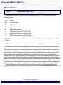
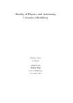
Code Sequencer
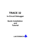
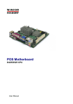
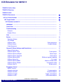
TRACE32-ICE11 uses a special code sequencer to classify CPU bus cycles on realtime emulation. This
feature allows perfect trigger and trace functions as prefetch cycles or idle cycles are not traced. The
sequencer offers many functions not available on competitive emulation systems.
-000016
-000015
-000014
-000013
-000012
-000011
-000010
-000009
-000008
-000007
-000006
-000005
-000004
-000003
-000002
D:0069F4
D:00240F
P:0069F4
P:0069F5
ldd
D:00FFFF
D:002414
D:002415
P:0069F6
P:0069F7
P:0069F8
subd
D:00FFFF
P:0069F9
P:0069FA
bgt
D:00FFFF
P:0069FB
rd
rd
opfetch
rd
$4,X
rd
rd
rd
opfetch
rd
rd
#$12
rd
opfetch
rd
6A0F
rd
opfetch
EC
01
EC
04
00
00
12
83
00
12
00
2E
14
00
3F
std
D:002414
D:002415
P:0069F3
tsx
P:0069F4
P:0069F5
ldd
D:002414
D:002415
P:0069F6
P:0069F7
P:0069F8
subd
P:0069F9
P:0069FA
bgt
P:0069FB
-000014
-000013
-000012
-000011
-000010
-000009
-000008
-000007
-000006
-000005
-000004
-000003
-000002
Without Sequencer
$4,X
wr-mem 00
wr-mem 03
opfetch 30
opfetch
sfetch
$4,X
rd-mem
rd-mem
opfetch
sfetch
sfetch
#$12
opfetch
sfetch
6A0F
opfetch
EC
04
00
03
83
00
12
2E
14
3F
With Sequencer
•
Perfect coverage analysis, prefetch cycles don't set read flags
•
No trigger on prefetch to data fields within code area
•
Program breakpoints may be set in data area to protect
•
Data breakpoints may be set in code area for protection
•
Select trace on data transfers only
•
Easy trigger on exception cycles
•
Selective trace
©1989-2015 Lauterbach GmbH
ICE Emulator for 68HC11
16
Basics
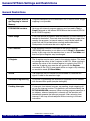
General SYStem Settings and Restrictions
General Restrictions
Program Break and Single Stepping in Internal
Memory
Program breakpoints are not executed if set in internal RAM. Single
stepping is not possible.
EPROM/ROM versions
Versions with internal program memory must be used in Test or
SingleTst mode or the internal EPROM must be turned off (EPON
bit in CONFIG register).
Stack Usage
If the stack pointer is placed in external memory, no stack memory is
needed for emulation. The stack size should be 9 bytes longer than
used by the program. In internal memory area 9 bytes below the
stack limit are first written before starting realtime emulation.
Stackpointer should never be set to register area.
COP Function
If the watchdog function is activated in the Option Register
(EEPROM) the emulator is not able to start in Single or Expanded
mode. In this case start the emulator has to start in Test Mode and
then the Option Register may be changed.
X Register
The X register may be set or reset in the register window. This does
not change the status of the X register in the CPU. When starting in
realtime the value of this shadow register is copied to the CPU. If
reset the X register may never be set again with the Register
command till the CPU is reset again either on target or by selecting
an emulation mode (SYStem.Mode).
4XCLK
The output pin 4XCLK should not be switched off, because this
signal is used for the emulator logic.
On-Board Programming
On-Board Programming with external programmers is not allowed
with the emulation probe (may be damaged).
Pending Interrupts
If interrupts from internal sources are pending, single stepping will
go into the interrupt routine. This behavior can be controlled by the
SETUP.IMASKASM command. When starting program execution at
an address, where a breakpoint is already set, the emulator will
immediately execute the interrupt program. After returning from
interrupt it will stop at the breakpoint without moving to the next
instruction.
©1989-2015 Lauterbach GmbH
ICE Emulator for 68HC11
17
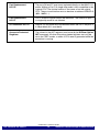
General SYStem Settings and Restrictions
Port Replacement
HC11D
The ports D6 and D7 may be not replaced directly on the 68HC11-D
probe. Writing to Port D in single chip mode is fully compatible to the
original CPU. The tristate function is the same as on the original
CPU. The port read function must on be done at address IOBASE+5
(05H, 1005H,…).
Port Replacement
HC11F
Port C direction register cannot be read back. The function of port C
in single chip mode is not affected.
I/O Relocation HC11C
Internal I/O and RAM must be relocated within the first 2 KByte of a
4 KByte block (A11 must be 0).
Access to Protected
Registers
The values for the INIT registers must be set by the SYStem.Option
INIT command. All other 64-cycle protected registers can only be
set in the TEST modes, or when a CPU reset is generated while the
emulation is running.
©1989-2015 Lauterbach GmbH
ICE Emulator for 68HC11
18
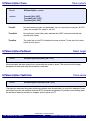
General SYStem Settings and Restrictions
SYStem.Option Trace
Trace options
Format:
SYStem.Option <option>
<option>:
TraceAll [ON | OFF]
TraceWait [ON | OFF]
TraceRes [ON | OFF]
TraceAll
Normally dummy cycles and prefetches are not traced by the analyzer. All CPU
cycles are traced if this option is set ON.
TraceWait
Normally wait cycles (the cycles between the WAIT command and the next
opcode fetch cycle).
TraceRes
The reset line on the CPU disables the trace analyzer. To see also this cycles
switch on this option.
SYStem.Option PerReset
Format:
Reset target
SYStem.OptionPerReset [ON | OFF]
When activated, the reset output line is active while the system is down. This ensures that the target
peripherals in reset state after the emulation is activated.
SYStem.Option TestClock
Format:
Clock sense
SYStem.Option TestClock [ON | OFF]
The emulator measures the system clock and switches down the emulator if a clock fail is detected. Some
derivatives stop also the oscillator when the STOP command is executed. To prevent from switching down
the emulation when the oscillator is stopped, set this option to OFF.
©1989-2015 Lauterbach GmbH
ICE Emulator for 68HC11
19
General SYStem Settings and Restrictions
SYStem.Option BASE
Format:
RAM and register mapping
SYStem.Option BASE <value>
The INIT register may be only set in the first 64 clock cycles after reset. Therefore the monitor program on
the emulator uses this value to remap internal memory and ports. This value must be same value used in
the program. On reset when running in realtime the target program must set the INIT register again to the
same value. This value must be set correctly it also defines the chip select of the port replacement chip and
the bus control while accessing internal memory. On the 68HC11C0 the lower byte defines the start address
of the I/O and the upper byte the start address of the RAM (INIT2). A value of 0ff in the upper byte disables
the internal RAM of the 68HC11C0.
SYStem.Option PLL
PLL mode
Format:
SYStem.Option PLL [ON | OFF]
OFF
The PLL operation is disabled
ON
The PLL operation is enabled
Derivatives with PLL (like 68HC11P) inside must be set to the correct mode before starting-up the emulation
system.
SYStem.Option RWMC
Memory strobe mode
Format:
SYStem.Option RWMC [ON | OFF]
OFF
The CPU memory access uses the R/W and E- signal.
ON
The CPU memory access uses the RD- and WR- signal.
The bus interface of the 68HC11C derivatives has 2 modes: An 6811 like mode with E- and R/W function
and an INTEL like mode with RD- and WR- signals.
©1989-2015 Lauterbach GmbH
ICE Emulator for 68HC11
20
General SYStem Settings and Restrictions
SYStem.Option TRANS
Format:
Transparent mode
SYStem.Option TRANS [ON | OFF]
The SYStem.Option Trans has effect on logical addresses smaller then 64K. If it is on, then accesses to this
area show the 64K of memory as seen by the CPU in the current paging configuration. This is the
transparent mode. If it is off, then in banked areas page zero of this area is shown and the contents of the
according page register has no influence. It has no effect on the memory access of the CPU executing user
code.
Address
Access to
000000--00ffff
current 64K address space (when TRANS is on)
000000--00ffff
page 0 (when TRANS is off)
010000--0ffffff
pages 1..0ff
100000--0ffffffff
current 64K address space
SYStem.Line EC
Strobe control
Format:
SYStem.Line EC [ON | OFF]
OFF
E signal is low if emulation is stopped, and active if emulation is running
ON
E signal is always active
In Expanded and Test mode, the access to peripheral devices is controlled by the E line and the address
bus. To stop access while the emulation is stopped, the emulator sets address output to 0ffxxh and switches
of the Write line. In this address range from 0xFF00--0xFFFF no I/O ports should be mapped. The CPU
accesses 0ffffh in idle/dummy cycles). Additionally the E line may also be stopped (Off). However some
targets use this line as clock signal. Stopping the E clock will force fatal errors in the target system.
©1989-2015 Lauterbach GmbH
ICE Emulator for 68HC11
21
General SYStem Settings and Restrictions
Exception Control
E::w.x
exception
OFF
ON
RESet
Activate
OFF
CpuReset
PerReset
IRQ
XIRQ
Enable
OFF
ON
CpuReset
PerReset
IRQ
XIRQ
Trigger
OFF
ON
RESet
STOP
IRQ
XIRQ
PULS
Puls
OFF
CpuReset
PerReset
IRQ
XIRQ
Puls
Single
Width
1.000us
PERiod
0.000
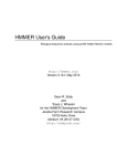
RESET Control
The reset line (input and output) is controlled by a bridge with analog switches and diodes.
RESET input
VCC
VCC
R1
R2
RESETTarget
S2
RESETEmulation CPU
S3
R3
S1
S4
GND
GND
R1 = 22K
R2 = 4.7K
R3 = 220
S1
Reset Target
X.Activate PerReset
X.Puls PerReset * running
S2
Reset Out
running
S3
Reset In
X.Enable Reset * running
S4
Internal Reset
Emulator Control
X.Activate CpuReset * running
X.Puls
CpuReset * running
©1989-2015 Lauterbach GmbH
ICE Emulator for 68HC11
22
Exception Control
eXception.Activate
Force exception
Format:
eXception.Activate CpuReset [ON | OFF]
Format:
eXception.Activate PerReset [ON | OFF]
Format:
eXception.Activate IRQ [ON | OFF]
Format:
eXception.Activate XIRQ [ON | OFF]
Format:
eXception.Activate OFF
CpuReset
Activates the RESET line of the CPU.
PerReset
Activates the RESET line on target side.
IRQ
Activates the IRQ line.
XIRQ
Activates the XIRQ line.
OFF
No activation of any exception line.
©1989-2015 Lauterbach GmbH
ICE Emulator for 68HC11
23
Exception Control
eXception.Enable
Enable exception
Format:
eXception.Enable CpuReset [ON | OFF]
Format:
eXception.Enable PerReset [ON | OFF]
Format:
eXception.Enabke IRQ [ON | OFF]
Format:
eXception.Enabke XIRQ [ON | OFF]
Format:
eXception.Enable OFF
Format:
eXception.Enable ON
CpuReset
Enables the RESET line of the CPU.
PerReset
Enables the RESET line on target side.
IRQ
Enables the IRQ line.
XIRQ
Enables the XIRQ line.
OFF
Disable all exception line.
ON
Enables all exception lines.
©1989-2015 Lauterbach GmbH
ICE Emulator for 68HC11
24
Exception Control
eXception.Trigger
Trigger on exception
Format:
eXception.Trigger RESET [ON | OFF]
Format:
eXception.Trigger STOP [ON | OFF]
Format:
eXception.Trigger IRQ [ON | OFF]
Format:
eXception.Trigger XIRQ [ON | OFF]
Format:
eXception.Trigger Pulse [ON | OFF]
Format:
eXception.Trigger OFF
Format:
eXception.Trigger ON
RESet
Trigger on RESET line.
STOP
Trigger on STOP line.
IRQ
Trigger on IRQ line.
XIRQ
Trigger on XIRQ line.
Pulse
Trigger on Pulse line.
ON
Trigger on all exception lines.
OFF
No trigger on any exception lines.
©1989-2015 Lauterbach GmbH
ICE Emulator for 68HC11
25
Exception Control
eXception.Pulse
Stimulate exception
Format:
eXception.Pulse PerReset [ON | OFF]
Format:
eXception.Pulse CpuReset [ON | OFF]
Format:
eXception.Pulse IRQ [ON | OFF]
Format:
eXception.Pulse XIRQ [ON | OFF]
Format:
eXception.Pulse OFF
CpuReset
Stimulate RESET line of the CPU.
PerReset
Stimulate RESET line on target side.
IRQ
Stimulate on IRQ line.
XIRQ
Stimulate on XIRQ line.
OFF
No stimulation on any exception line.
©1989-2015 Lauterbach GmbH
ICE Emulator for 68HC11
26
Exception Control
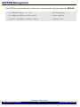
EEPROM Management
The EEPROM may be initialized with standard set or load commands using the storage class EEPROM:
d.s EEPROM:0xB600 2 3 4 5
; setting bytes
d.s EEPROM:0xB600++0x1ff 0x0ff
; clear EEPROM
d.load.b epromdata EEPROM:0xB600
; loading data
©1989-2015 Lauterbach GmbH
ICE Emulator for 68HC11
27
EEPROM Management
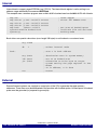
Banked Target Systems
In banked systems the upper address lines are either supplied internally or by the external bank probe. 8
additional lines offer 256 different memory banks. Accessing the different pages is done by extending all
memory and pc addresses to 24 bit. The address bits A16 to A23 select the memory bank. Every command
which makes a memory access first calls a special bank driver subroutine to select the temporary memory
bank. On realtime emulation the bank number is traced on the upper 8 bits of the address bus. On
breakpoints the bank address is stored back to the MSB of the program counter.
Format:
SYStem.BankFile <file>
This command load the bank driver. The bank driver is a special subroutine to select the actual bank.
Loading a special bank driver gives a maximum in flexibility to the user. A bank address delivered by the
emulator may be used to set microcontroller ports or external MMUs in the target system. The bank file
consists of a code number defining the bank operation mode and a code area which consists of a subroutine
to set the correct bank state. Writings to internal CPU ports may be executed directly, while ports in target
systems must be accessed by a special system call to address 1800H. The internal bank address is places
in accu A when calling the subroutine. The reason for the call is placed in B (0=init, 1=read, 2=write, 3=go,
4=breakpoint). Register IX holds the address for read or write functions. After a breakpoint (code 4) the
current bank can be stored at the address pointed to by register IY plus 21 (decimal). The write function to
the target system needs the address in IX and the data in accu A. The BNK register holds the physical bank
number. The PP (Program Pointer) register hold the logical 24-bit PC address. The translation between
logical bank and physical bank (also for the common areas) is done by the MMU command.
Format:
SYStem.Bank <option>
<option>:
OFF
Internal
External
©1989-2015 Lauterbach GmbH
ICE Emulator for 68HC11
28
Banked Target Systems
Internal
Internal bank to support paged EPROMs (e.g 27C513). The internal bank register is set by writing to an
address range selected by the command MAP.Bank
This example uses a common program area on 0x0--0x3fff a banked area from 0x4000--0x7fff with 4 banks:
map.res
map.mirror p:0x0--0x03fff 0x10000
map.mirror p:0x0--0x03fff 0x20000
map.mirror p:0x0--0x03fff 0x30000
map.bank
0x4000--0x7fff
system.bankfile banksel.bnk
system.up
; reset mapper
; mirror for common area
; set area of banked eprom
; load bank file and activate
; banking mode
Bank drivers are special subroutines (max. length 256 bytes) to set the bank or an external mmu:
org 27FFH
db
1
bank:
; select internal mode
; accu a is bank address
org $2800
; destination area in system memory
ldx $4000
jsr $1800
;
;
;
;
;
;
rts
set IX to banked area
subroutine to write byte to target
system setting the page register in the
EPROM
IX is address, A is date
return
External
External banked systems use a register or output pins of the CPU to generate the upper memory
addresses. These lines must be feedbacked to the emulator with the bank probe. Unused inputs of the bank
probe must be grounded (or jumpered to ground pin).
©1989-2015 Lauterbach GmbH
ICE Emulator for 68HC11
29
Banked Target Systems
This example uses a common program area on 0x0--0x3fff a banked area from 0x4000--0x7fff with 4 banks
In this example the bank is selected by bit 6 and 7 of Port A:
map.res
map.mirror p:0x0--0x03fff 0x10000
map.mirror p:0x0--0x03fff 0x20000
map.mirror p:0x0--0x03fff 0x30000
system.bankfile banksel.bnk
system.up
; reset mapper
; mirror for common area
; load bank file and activate
; banking
org 27FFH
db
2
bank:
org $2800
ldab
andb
stab
asla
asla
asla
asla
asla
asla
oraa
staa
#$03f
$1000
$1000
; select external mode
; accu a is bank address
; destination area in system memory
;
;
;
;
;
mask bit 6+7
store back
shift 6 times
store back and set bank address
$1000
$1000
rts
; return
Now the bank select is done by an external register selected at A000h
org 27FFH
db
2
bank:
org $2800
ldx #$A000
jsr $1800
rts
; select external mode
; accu a is bank address
; destination area in system memory
;
;
;
;
set IX to banked area
subroutine to write byte to emulation
ram setting bank register
IX is address, A is date return
©1989-2015 Lauterbach GmbH
ICE Emulator for 68HC11
30
Banked Target Systems
The next examples shows the map and load commands for translated bank numbers:
This example uses a common program area on 0x0--0x7fff and a banked area from 0x8000--0xffff with 2
banks:
system.bankfile banksel.bnk
; load bank file
; (uses physical
; banks)
system.mode ai
map.res
map.mirror
; reset mapper
; mirror for common
; area
p:0x0--0x7fff 0x10000
map.ram p:0x0--0x0ffff
; map memory in
; banks and
common
map.ram p:0x18000--0x1ffff
map.intern
symbol.reset
mmu.reset
mmu.create p:0x00000--0x07fff
mmu.create p:0x08000--0x0ffff
mmu.create p:0x00000--0x07fff
mmu.create p:0x18000--0x1ffff
mmu.on
p:0x00000--0x07fff
p:0x08000--0x0ffff
p:0x10000--0x17fff
p:0x18000--0x1ffff
d.load.u applic.dbg /nc
; load file from
; ICC6811 (IAR)
Memory Access Routines
Addr
Function
Address
Data
Result
1800H
MemWrite
IX
A
-
1808H
MemRead
IX
-
A
©1989-2015 Lauterbach GmbH
ICE Emulator for 68HC11
31
Banked Target Systems
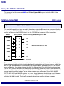
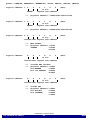
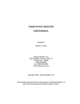
MMU
Using the MMU for 68HC11K
This command and the commands MMU and SYStem.Option MMU support the built-in MMU of the
68HC11K/P processors.
SYStem.Option MMU
Format:
MMU usage
SYStem.Option MMU <mask>
The mask defines which port pins are used for the address extension. Bits zero to five correspond directly to
the pins of port G (XA13 to XA18). A set bit will activate the MMU function on the pin. Bit six is used to
control the behavior of the CSPROG line. If set, the CSPROG line is used as A19 for the emulator.
68HC11
CSPROG
XA18
XA17
XA16
XA15
A15
XA14
A14
XA13
A13
Multiplexer controlled by SYStem.Option MMU
1
0
1
0
1
0
1
0
1
0
1
0
1
0
A0..12
6
A19
5
A18
4
A17
3
A16
2
A15
1
A14
0
A13
Emulator Address Bus
A0..A12
The analyzer and all memory systems and breakpoints are based on the physical address. The display in
the analyzer can be both physical or logical addresses. A logical address can have two formats: smaller than
64K or larger. Smaller addresses are assumed to be a logical address as seen by the CPU in the current
mmu configuration. If an address is larger than 64K, the address bits A17 to A22 define the physical page
(XA13..XA18) used for the access. To access page zero absolute, address A16 must be set, otherwise the
address would be interpreted as a logical address in the current CPU space. A logical address alone doesn't
unique identify the physical address, as the address depends also on the setup of the PGAR, MMSIZ,
CSCTL, INIT, INIT2 and MMWBR registers. As a result, logical addresses should only be used, if the mmu
registers were already setup. Accessing internal resources (RAM or peripherals) is handled like an access
outside of the MMU window. The following schematic shows these relations for some examples:
©1989-2015 Lauterbach GmbH
ICE Emulator for 68HC11
32
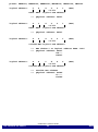
MMU
preset: PGAR=3F, MMSIZ=22, MMWBR=84, MM1CR=10, MM2CR=20, INIT=01
logical address:
5
0
XA18..XA13
-->
logical address:
0
logical address:
0
1
4
5
6
7
16 bit
logical CPU address
0
0
4
(Hex)
(Hex)
mmu window 1 at logical address 4000..7fff
physical address: 00567
+10--=10567
d
e
f
16 bit
current-mmu logical CPU address
-->
-->
(Hex)
physical address: 00567
5
6
7
16 bit
current-mmu logical CPU address
-->
-->
logical address:
5
6
7
16 bit
logical CPU address
physical address: 50567
XA18..XA13
-->
4
0
c
(Hex)
outside mmu windows
physical address: 0cdef
+7---=7cdef
©1989-2015 Lauterbach GmbH
ICE Emulator for 68HC11
33
MMU
To activate the correct address translation for breakpoints, the MMU command must be activated. The
following script will prepare the 68HC11K4 for using the MMU with XA13..XA17 and CSPROG line to select
between RAM and ROM:
map.ram a:0x0++0x3ffff
map.ram a:0x80000++0x7fff
map.i
; memory at physical
; locations
sys.cpu test
sys.o mmu 5f
; select TEST mode
; activate MMU mode for
; probe (with CSPROG)
sys.m ai
mmu.res
mmu.c 0x008000--0x00bfff
mmu.c 0x000000--0x0002ff
mmu.c 0x000300--0x000fff
mmu.c 0x001000--0x00107f
mmu.c 0x001080--0x007cff
mmu.c 0x007d00--0x007fff
mmu.c 0x01c000--0x01ffff
mmu.c 0x04c000--0x04ffff
...
mmu.c 0x34c000--0x34ffff
mmu.c 0x3cc000--0x3cffff
mmu.on
0x38000--0x3bfff
0x0b0000--0x0b02ff
0x80300--0x80fff
0x0b1000--0x0b107f
0x81080--0x87cff
0x0b7d00--0x0b7fff
0x00000--0x03fff
0x04000--0x07fff
0x34000--0x37fff
0x3c000--0x3ffff
d.s 0x2d 0x1f
d.s 0x56 0x32
d.s 0x57 0x0c
d.s 0x58 0x3c 0x0
d.s 0x5b 0x25
y.res
d.load.ws applic.h11 /nc
r.res
;
;
;
;
;
;
;
;
;
common area memory
(16K)
internal RAM
RAM memory
internal registers
RAM memory (32K)
RAM memory
ROM page #0
ROM page #1
; ROM page #13
; ROM page #15
; activate
;
;
;
;
;
;
;
;
PGAR PINs XA13..XA17
used as address lines
two windows
window 1 at c000,
window 2 at 0000
offset values for
MM1CR and MM2CR
32K CSPROG size
;
;
;
;
clear symbols
load application
get reset vector for
PC
The MMU translation table is used for translating physical addresses (analyzer, trigger) to logical addresses
and logical addresses to physical addresses. If a logical address is not defined in the table, the logical to
physical translation is done by reading the MMU registers of the CPU and calculating the physical address.
This calculation doesn't take care about memory areas, which are overlaid by internal memory or i/o. It is
strongly recommended to defined all logical and physical addresses in the MMU table.
NOTE: When accessing memory with physical addressing (A:) by the CPU the address for the CPU is
transformed to a bank and offset using the MMU table. Physical addressing of emulation memory is always
possible without transformation (EA:).
©1989-2015 Lauterbach GmbH
ICE Emulator for 68HC11
34
MMU
Using the MMU for 68HC11C
This command and the commands MMU and SYStem.Option MMU support the built-in MMU of the
68HC11C processors.
Format:
SYStem.Option MMU <mask>
The mask defines which port pins are used for the address extension. The following table shows the
possible values:
mask
mode
00
No MMU used
01
MMU 64K expansion
03
MMU 128K expansion
07
MMU 256K expansion
11
MMU 64K expansion, CSPROG used
13
MMU 128K expansion, CSPROG used
17
MMU 256K expansion, CSPROG used
WARNING: Switch off the internal ROM when using the 68HC11C0 with MMU in TEST mode (bit RBOOT
in HPRIO).
In TEST mode the external memory at the address of the internal RAM or I/O location cannot be accessed.
When CSPROG is used to distinguish different memories, is will be used as physical A19 for the emulator.
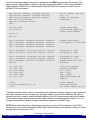
The analyzer and all memory systems and breakpoints are based on the physical address. The display in
the analyzer can be both physical or logical addresses. A logical address can have two formats: smaller than
64 K or larger. Smaller addresses are assumed to be a logical address as seen by the CPU in the current
MMU configuration. If an address is larger than 64K, the address bits A16 to A23 define the physical
address A10 to A17 (offset for MXADR) used for the access. To distinguish an access to page zero absolute
from a logical address A24 must be set. Otherwise the address would be interpreted as a logical address in
the current CPU space. A logical address alone doesn't unique identify the physical address, as the address
depends also on the setup of the VA, PSA, PEA and PGEN registers. As a result, logical addresses should
only be used, if the mmu registers were already setup. Accessing internal resources (RAM or peripherals) is
handled like an access outside of the MMU window. Accesses outside the MMU set A16 and A17 according
to the MXADRH register (except CSV accesses). This feature can also be used for a second banking
outside the CSPROG area. If this area is not banked, it must be mirrored by MAP.MIRROR commands. The
following schematic shows these relations for some examples:
©1989-2015 Lauterbach GmbH
ICE Emulator for 68HC11
35
MMU
preset: PGEN=xF, MXADRH=03, MXADRL=FC, VA=F0, PSA=60, PEA=B0, INIT=01
logical address: 1
5
0
MXADR
-->
logical address: 1
0
MXADR
logical address: 0
0
7
8
9
16 bit
logical CPU address
6
7
8
9
16 bit
logical CPU address
logical address:
0
logical address:
0
6
0
0
c
(Hex)
outside mmu windows
physical address: 0cdef
set MXADRH
+30000
A19 (no CSPROG) +80000
=bcdef
d
e
f
16 bit
current-mmu logical CPU address
-->
-->
(Hex)
MMU window
physical address: 06789
+MXADR
+3fc00
=06389
d
e
f
16 bit
current-mmu logical CPU address
-->
-->
(Hex)
physical address: 00000+6789-6000=00789
7
8
9
16 bit
current-mmu logical CPU address
-->
-->
(Hex)
physical address: 14000+6789-6000=14789
0
-->
6
0
f
(Hex)
inside CSV
physical address: 0fdef
set A16/A17
+30000
A19 (CSPROG)
+00000
=3fdef
©1989-2015 Lauterbach GmbH
ICE Emulator for 68HC11
36
MMU
To activate the correct address translation for breakpoints, the MMU command must be activated. The
following script (../demo/m68hc11/etc/mmu_c0.cmm) will prepare the 68HC11C0 for using the MMU in
256K mode with CSPROG line to select between RAM and ROM (the example was taken from the
MC68HC11C0 User Manual):
map.mirror p:0x80000--0x85fff 0x090000
map.mirror p:0x80000--0x85fff 0x0a0000
map.mirror P:0x80000--0x85fff 0x0b0000
map.ram a:0x0++0x3ffff
map.ram a:0x80000++0x7fff
map.i
;
;
;
;
mirror common area and
int. I/O
memory at physical
locations
sys.cpu test
sys.o mmu 17
; select TEST mode
; activate MMU mode for
; probe (with CSPROG)
sys.m ai
mmu.res
mmu.c
mmu.c
mmu.c
mmu.c
0x000000--0x005fff
0x000000--0x005fff
0x000000--0x005fff
0x000000--0x005fff
0x080000--0x085fff
0x090000--0x095fff
0x0a0000--0x0a5fff
0x0b0000--0x0b5fff
; common area memory
; and internal I/O and RAM
mmu.c 0x1006000--0x100afff 0x00000--0x04fff
mmu.c 0x1146000--0x114afff 0x05000--0x09fff
...
mmu.c 0x1dc6000--0x1dcafff 0x37000--0x3bfff
mmu.c 0x1f06000--0x1f0afff 0x3c000--0x3cfff
mmu.c 0x00d000--0x00ffff 0x03d000--0x03ffff
mmu.on
; ROM page #0 (20K)
; ROM page #1 (20K)
;
;
;
;
ROM page #11 (20K)
ROM page #12 (4K)
common area CSV (12K)
activate
d.s
d.s
d.s
d.s
d.s
d.s
;
;
;
;
;
;
;
turn off bootprom
disable watchdog
VA = 0d000
PSA = 6000
PEA = 0b000
PGEN enable MMU and
CSPROG
0x3c
0x3f
0x40
0x42
0x43
0x71
0x75
0x05
0x0d0
0x60
0x0b0
0x0f
y.res
d.load.xxx applic.h11 /nc
r.res
; clear symbols
; load application
; get reset vector for PC
The MMU translation table is used for translating physical addresses (analyzer, trigger) to logical addresses
and logical addresses to physical addresses. If a logical address is not defined in the table, the logical to
physical translation is done by reading the MMU registers of the CPU and calculating the physical address.
This calculation doesn't take care about memory areas, which are overlaid by internal memory or i/o. It is
strongly recommended to defined all logical and physical addresses in the MMU table.
NOTE: When accessing memory with physical addressing (A:) by the CPU the address for the CPU is
transformed to a bank and offset using the MMU table. Physical addressing of emulation memory is always
possible without transformation (EA:).
©1989-2015 Lauterbach GmbH
ICE Emulator for 68HC11
37
MMU
Memory Classes
Memory Class
Description
C:
Specify the same address-area (CPU-access)
D:
P:
A:
Absolute memory access (requires MMU-table)
AD:
AP:
EEPROM:
EEPROM write
E:
Emulation memory access (dualported)
ED:
EP:
EA:
Physical address (68HC11-K4/KA4/N4 only)
C:, P: and D:
This storage classes operate on the same physically memory. They are only used to be compatible with
other emulation probes. CPU internal registers and memory may not be accessed dualported, by mapping
memory to the same address range data written to the internal memory are also present in the emulation
memory.
EEPROM:
This storage class is used to program the internal EEPROM. On read cycles there is no difference to the
access mode with C: or D:. On write cycles the monitor program executes an EEPROM write protocol.
d.s
EEPROM:0E00
d.load.b test.bin
"
Test
"
EEPROM:0e00
EA:
The storage class EA: is only used for the 68HC11-K/P/C CPU and only if the MMU option is selected.
©1989-2015 Lauterbach GmbH
ICE Emulator for 68HC11
38
Memory Classes
State Analyzer
Keywords for the Trigger Unit
Input Event
Meaning
Analyzer Hardware
ECC8
HAC
HA120
SA120
DATA
Data access
MEM+STACK+INT+X
X
X
X
X
DUMMY
DUMMY cycle
X
X
X
X
FETCH
any fetch cycle
OPFETCH+SFETCH
X
X
X
X
INT
Internal memory access
INTREAD+INTWRITE
X
X
X
X
INTREAD
Read internal memory
X
X
X
X
INTWRITE
Write internal memory
X
X
X
X
IREQ
Interrupt request line
X
X
MEM
Memory cycle
MEMREAD+MEMWRITE
X
X
X
X
MEMREAD
Memory read cycle
X
X
X
X
MEMWRITE
Memory write cycle
X
X
X
X
OPDATA
Fetch or data cycle
FETCH+DATA
X
X
X
X
OPFetch
1st cycle of command
X
X
X
X
PD0..PD5
Port D lines access
X
X
PIRQ
Interrupt request for port B or C (port
replacement)
X
X
PORT
Input line from port analyzer
X
X
PREFETCH
Prefetch cycle (normally not sampled)
X
X
X
X
Read
Read access
FETCH+PREFETCH+DUMMY+MEMREAD +STACKREAD
+INTREAD+XREAD
X
X
X
X
SFETCH
Sequential fetch (2nd opcode)
X
X
X
X
STACK
Stack access
STACKREAD+STACKWRITE
X
X
X
X
STACKREAD
Stack read cycle (internal or memory)
X
X
X
X
STACKWRITE
Stack write cycle (internal or memory)
X
X
X
X
©1989-2015 Lauterbach GmbH
ICE Emulator for 68HC11
39
State Analyzer
WAIT
Wait cycle (cycles between WAIT opcode
and interrupt, normally not sampled)
Write
Write access
MEMWRITE+STACKWRITE+INTWRITE+XWRITE
X
X
Exception cycle
XREAD+XWRITE
X
XIREQ
XIRQ input
XREAD
Exception read (e.g. vector read)
X
XWRITE
Exception write (e.g. interrupt stack)
X
X
X
X
X
X
X
X
X
X
X
X
X
X
X
X
X
For not CPU-specific keywords, see non-declarable input variables in ”ICE/FIRE Analyzer Trigger Unit
Programming Guide” (analyzer_prog.pdf).
Keywords for the Display
WAIT
Wait for interrupt, normally not sampled
EC
E clock of CPU
PA0..PA7
Port A
PD0..PD5
Port D
PIRQ
Port Interrupt
XIRQ
©1989-2015 Lauterbach GmbH
ICE Emulator for 68HC11
40
State Analyzer
Port Analyzer
Keywords for the Port Analyzer
Port.A0..Port.A7
Port.B0..Port.B7
Port.C0..Port.C7
Port.D0..Port.D7
Port.E0..Port.E7
not Version D
Port.F0..Port.F7
Port.G0..Port.G7
Port.H0..Port.H5
Port.WR..Port.WR
Port.IRQ..P.IRQ
Version A,D,E,F
Port.XIRQ..P.XIRQ
Version A,D,E,F
Port.H6..Port.H7
Version H,J
Port.EC
Version F,H,J
Port.AS
Version A,D,E
Additional Trace Channels
Not used trace channels on Port Analyzer are connected to pins placed on the emulation module.
©1989-2015 Lauterbach GmbH
ICE Emulator for 68HC11
41
Port Analyzer
Modul M68HC11-A/E/D
25 23 21 19 17 15 13 11 9
26 24 22 20 18 16 14 12 10
1
2
3
4
5
6
7
8
Port.F0
Port.F1
Port.F2
Port.F3
Port.F4
Port.F5
Port.F6
Port.F7
9
10
11
12
13
14
15
16
Port.G0
Port.G1
Port.G2
Port.G3
Port.G4
Port.G5
Port.G6
Port.G7
17
18
19
20
21
22
Port.H0
Port.H1
Port.H2
Port.H3
Port.H4
Port.H5
23..26
GND
7
8
5
6
3
4
1
2
Modul M68HC11-F
5
6
1
2
3
4
5
6
3
4
1
2
Port.H0
Port.H1
Port.H2
Port.H3
Port.H4
Port.H5
©1989-2015 Lauterbach GmbH
ICE Emulator for 68HC11
42
Port Analyzer
Compilers
Language
Compiler
Company
Option
Comment
ASM
A6801
IAR Systems AB
UBROF
C
CX68HC11
Cosmic Software
COSMIC
Source level
debugging
w. Banking and K4
MMU
C
HICROSS-C
HICROSS
C
CC11
C
C
C
GCC11
ICC6811
C11
Freescale
Semiconductor, Inc.
Freescale
Semiconductor, Inc.
Generic
IAR Systems AB
Introl Corporation
COFF
DBX
UBROF
ICOFF
Banking support
©1989-2015 Lauterbach GmbH
ICE Emulator for 68HC11
43
Compilers
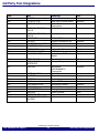
3rd Party Tool Integrations
CPU
Tool
Company
ALL
ALL
ALL
ADENEO
X-TOOLS / X32
CODEWRIGHT
ALL
CODE CONFIDENCE
TOOLS
CODE CONFIDENCE
TOOLS
EASYCODE
ECLIPSE
RHAPSODY IN MICROC
RHAPSODY IN C++
CHRONVIEW
LDRA TOOL SUITE
UML DEBUGGER
Adeneo Embedded
blue river software GmbH
Borland Software
Corporation
Code Confidence Ltd
ALL
ALL
ALL
ALL
ALL
ALL
ALL
ALL
ALL
ALL
ALL
ALL
ALL
ALL
ALL
ALL
ALL
ALL
ALL
ALL
ALL
ATTOL TOOLS
VISUAL BASIC
INTERFACE
LABVIEW
Host
Windows
Code Confidence Ltd
Linux
EASYCODE GmbH
Eclipse Foundation, Inc
IBM Corp.
IBM Corp.
Inchron GmbH
LDRA Technology, Inc.
LieberLieber Software
GmbH
MicroMax Inc.
Microsoft Corporation
Windows
Windows
Windows
Windows
Windows
Windows
Windows
NATIONAL
INSTRUMENTS
Corporation
Open Source
Parasoft
Rapita Systems Ltd.
RistanCASE
Symtavision GmbH
The MathWorks Inc.
Timing Architects GmbH
Undo Software
Vector Software
Windows
CODE::BLOCKS
C++TEST
RAPITIME
DA-C
TRACEANALYZER
SIMULINK
TA INSPECTOR
UNDODB
VECTORCAST
WINDOWS CE PLATF.
BUILDER
Windows
Windows
Windows
Windows
Windows
Windows
Windows
Windows
Windows
Windows
Windows
Linux
Windows
Windows
©1989-2015 Lauterbach GmbH
ICE Emulator for 68HC11
44
3rd Party Tool Integrations
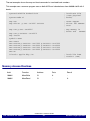
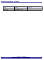
Realtime Operation Systems
Name
Company
Comment
CMX-RTX
RTX51/-tiny
CMX Systems Inc.
ARM Germany GmbH
©1989-2015 Lauterbach GmbH
ICE Emulator for 68HC11
45
Realtime Operation Systems
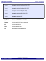
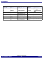
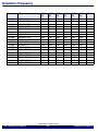
Emulation Frequency
Module
CPU
F-W015
F-W035
S-W015
S-W035
S-W115
S-W135
LA-6682
LA-6681
LA-6685
LA-6682
LA-6683
LA-6684
LA-6684
LA-6693
LA-6684
LA-6688
LA-6688
LA-6685
LA-6682
LA-6684
LA-6684
LA-6688
LA-6682
MC68HC11A
MC68HC11C
MC68HC11D
MC68HC11E
MC68HC11F
MC68HC11G
MC68HC11K
MC68HC11KA
MC68HC11KW
MC68HC11N
MC68HC11P
MC68HC11PH
MC68HC711D
MC68HC711E
MC68HC711K
MC68HC711KA
MC68HC711P
MC68HC811E
2.0+
3.0+
4.0+
2.0+
4.0+
4.0+
4.0+
4.0+
4.0+
4.0+
4.0+
4.0+
2.0+
2.0+
4.0+
4.0+
4.0+
2.0+
2.0+
3.0+
4.0+
2.0+
4.0+
4.0+
4.0+
4.0+
4.0+
4.0+
4.0+
4.0+
2.0+
2.0+
4.0+
4.0+
4.0+
2.0+
2.0+
3.0+
4.0+
2.0+
4.0+
4.0+
4.0+
4.0+
4.0+
4.0+
4.0+
4.0+
2.0+
2.0+
4.0+
4.0+
4.0+
2.0+
2.0+
3.0+
4.0+
2.0+
4.0+
4.0+
4.0+
4.0+
4.0+
4.0+
4.0+
4.0+
2.0+
2.0+
4.0+
4.0+
4.0+
2.0+
2.0+
3.0+
4.0+
2.0+
4.0+
4.0+
4.0+
4.0+
4.0+
4.0+
4.0+
4.0+
2.0+
2.0+
4.0+
4.0+
4.0+
2.0+
2.0+
3.0+
4.0+
2.0+
4.0+
4.0+
4.0+
4.0+
4.0+
4.0+
4.0+
4.0+
2.0+
2.0+
4.0+
4.0+
4.0+
2.0+
DRAM
©1989-2015 Lauterbach GmbH
ICE Emulator for 68HC11
46
Emulation Frequency
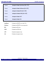
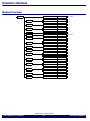
Emulation Modules
Module Overview
LA-6680
MC68HC11G
PLCC68
LA-6682
MC68HC11A
MC68HC11A
DIL48
PLCC52
LA-6681
MC68HC11C
FP64
LA-6685
MC68HC11D
MC68HC11D
DIL40
PLCC44
LA-6682
MC68HC11E
PLCC52
LA-6690
MC68HC11E
PLCC52
LA-6683
MC68HC11F
PLCC68
MC68HC11K
PLCC84
MC68HC11KA
PLCC68
LA-6693
MC68HC11KW
ET100-QF49
LA-6684
MC68HC11N
PLCC84
MC68HC11P
PLCC84
MC68HC11PH
PLCC84
LA-6685
MC68HC711D
MC68HC711D
DIL40
PLCC44
LA-6682
MC68HC711E
MC68HC711E
DIL48
PLCC52
MC68HC711K
PLCC84
MC68HC711KA
PLCC68
LA-6688
MC68HC711P
PLCC84
LA-6682
MC68HC811E
PLCC52
3.0..5.5V
3.0..5.5V
LA-6684
LA-6688
LA-6684
©1989-2015 Lauterbach GmbH
ICE Emulator for 68HC11
47
Emulation Modules
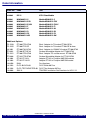
Order Information
Order No.
Code
Text
LA-6680
ICE-11
ICE-11 Base Module
LA-6681
LA-6682
LA-6690
LA-6683
LA-6684
LA-6685
LA-6688
LA-6693
M-MC68HC11-C
M-MC68HC11-E-5V
M-MC68HC11-E-3.3V
M-MC68HC11-F
M-MC68HC11-K
M-MC68HC11-D
M-MC68HC11-P2
M-MC68HC11-KW
Module MC68HC11-C
Module MC68HC11-E 5V
Module MC68HC11-E 3.3V
Module MC68HC11-F1
Module MC68HC11-K4
Module MC68HC11-D3
Module MC68HC11-P2
Module MC68HC11-KW
Additional Options
TO-1250
ET100-ETO-QF49
TO-1255
ET100-ETO-SE
YA-1091
ET100-EYA-QF49
ET-1092
ET100-SET-QF49
TO-1251
ET100-STO-QF49
ET-1000
ET132-ETS-QF03
LA-1004
ET132-FP132-L
LA-1003
ET132-FP132-R
LA-6450
PA64
LA-1923
PLCC-BLOCK-68
LA-1926
PLCC-TEST-ADAPTER-68
LA-8806
SIM-12
Emul. Adapter for T0 socket ET100-QF49
Emul. Adapter for T0 socket ET100-SE 0.4mm
Emul. Adapter for YAMAICHI socket ET100-QF49
Surface Mountable Adapter for ET100-QF49
Emul. Adapter TO-surface mount. ET100-QF49
Surface Mountable Adapter for ET132-QF03
Adapter ET132 to Footprint AMP/3M sockets
Adapter ET132 to Footprint AMP/3M socket
Port Analyzer
PLCC Block 68 Pins
PLCC Test Adapter 68 Pins
TRACE32 Instruction Set Simulator for HC11/12
©1989-2015 Lauterbach GmbH
ICE Emulator for 68HC11
48
Emulation Modules
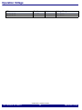
Operation Voltage
CPU
Module
Adapter
Voltage Range
MC68HC11E
MC68HC11G
LA-6690
-
-
3.0 .. 5.5 V
3.0 .. 5.5 V
©1989-2015 Lauterbach GmbH
ICE Emulator for 68HC11
49
Operation Voltage
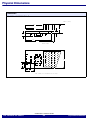
Physical Dimensions
Dimension
LA-6681
M-MC68HC11-C
cable (400)
64
37
13
9
93
103
SIDE VIEW
1
PLCCsocket
64
1
21 16
13
30
TOP VIEW (all dimensions in mm)
©1989-2015 Lauterbach GmbH
ICE Emulator for 68HC11
50
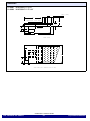
Physical Dimensions
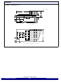
Dimension
LA-6682
LA-6690
M-MC68HC11-E-5V
M-MC68HC11-E-3.3V
cable (400)
63
Port Repl.
68HC11A/E
37
13
PLCC-52
9
26
DIL-48
93
103
SIDE VIEW
PLCCsocket
1
64
20
:
15
TOP VIEW (all dimensions in mm)
©1989-2015 Lauterbach GmbH
ICE Emulator for 68HC11
51
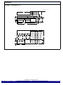
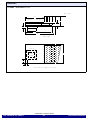
Physical Dimensions
Dimension
LA-6683
M-MC68HC11-F
cable (400)
63
68HC11F
Port Repl.
37
13
PLCC-68
9
93
103
SIDE VIEW
PLCCsocket
69
1
20
8
TOP VIEW (all dimensions in mm)
©1989-2015 Lauterbach GmbH
ICE Emulator for 68HC11
52
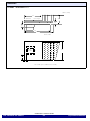
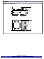
Physical Dimensions
Dimension
LA-6684
M-MC68HC11-K
cable (400)
67
68HC11K/N
Port Repl.
37
13
9
PLCC84
PLCC68
26
97
107
SIDE VIEW
HC11/K/N
HC11/KA
PLCCsocket
1
PLCCsocket
71
1
21
17
38
TOP VIEW (all dimensions in mm)
©1989-2015 Lauterbach GmbH
ICE Emulator for 68HC11
53
Physical Dimensions
Dimension
LA-6685
M-MC68HC11-D
cable (400)
68
68HC11D
Port Repl.
37
13
9
PLCC44
DIL-40
97
108
SIDE VIEW
PLCCsocket
1
64
21
17
TOP VIEW (all dimensions in mm)
©1989-2015 Lauterbach GmbH
ICE Emulator for 68HC11
54
Physical Dimensions
Dimension
LA-6688
M-MC68HC11-P2
cable (400)
66
68HC11P
Port Repl.
37
13
9
PLCC84
97
107
SIDE VIEW
HC11/P
PLCC-
69
1
socket
18
6
TOP VIEW (all dimensions in mm)
©1989-2015 Lauterbach GmbH
ICE Emulator for 68HC11
55
Physical Dimensions
Dimension
LA-6693
M-MC68HC11-KW
cable (400)
75
37
13
9
105
115
SIDE VIEW
69
PIN 1
8
18
TOP VIEW (all dimensions in mm)
©1989-2015 Lauterbach GmbH
ICE Emulator for 68HC11
56
Physical Dimensions
Adapter
Not necessary.
©1989-2015 Lauterbach GmbH
ICE Emulator for 68HC11
57
Adapter