1
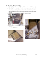
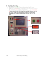
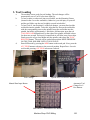
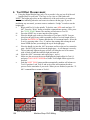
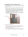
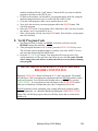
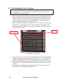
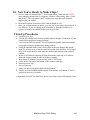
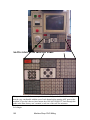
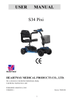
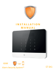
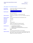
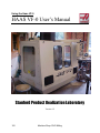
Using the Haas VF-0
HAAS VF-0 User’s Manual
Stanford Product Realization Laboratory
Version 1.2
152
Machine Shop: CNC Milling
1. Machine (Pre) Start-Up
a. Check Oil Reservoir (at rear of machine). If Oil Level is below MIN line, notify a
TA and help them add way oil to this reservoir.
b. Check Coolant Level (in rollaway unit beneath the machine). Pull out the coolant
unit and open the chip trap. Check to make sure the coolant level is up to at least
half of the tank. Also, check to make sure the chip basket is clear of chips. Empty
if needed.
c. Check compressed air supply – is it on? 85 lbs. pressure is normal.
d. Ensure that there are no chips in the Spindle Taper (check with finger, wipe with
clean rag)
Oil Reservoir
Coolant Unit
Chip Trap in Coolant Unit
Machine Shop: CNC Milling
153
2. Machine Start Up
a. Press the Green POWER ON Button at the control panel (top left corner).
b. Wait for the machine to boot up. It should flash an alarm message and say “servos
off.” Press the red RESET button to clear all alarms.
c. Make sure the emergency stop button is pulled out and press the AUTO POWER
UP button on the tool panel. The machine will go through a calibration cycle and
zero all axes. MAKE SURE THE DOOR IS CLOSED! The HAAS will not
perform any table or spindle command with the doors open. This is for your
safety.
154
Machine Shop: CNC Milling
3. Tool Loading
a.
b.
c.
d.
The machine is now ready for tool loading. The tool changer will be
automatically set to Tool #1 after Auto Start-Up.
To load a cutter (or other tool) into a tool holder, use the Mounting Fixture
(located in the vise on the worktable). Otherwise, you risk injury to yourself
and the tool. Make sure the tool is tightly secured in its holder!
To load Tool #1 into Position #1 on the tool changer, you must first load the
tool holder into the spindle. To do this, align the two slots on the tool holder
with the corresponding posts on the spindle. Insert the tool holder into the
spindle, but hold it approximately 1 inch below full insertion; press the red
TOOL RELEASE button directly to the right of the spindle, and hold it down
for about one second. The burst of compressed air will blow away loose chips.
Firmly press the aligned tool holder into the spindle, and release the TOOL
RELEASE button. The tool will be sucked into position. KEEP PRESSURE
ON THE TOOL HOLDER UNTIL IT IS IN PLACE.
Enter MDI mode by pressing the MDI button on the touch pad. Next, press the
ATC FWD button to advance to the next tool position. Repeat Part c for each
tool loaded, pressing ATC FWD in between each tool.
4. Workpiece Loading
Tool Carriage
Spindle and Tool Release Button on VF0
Automatic Tool
Change Fwd /
Rev Buttons
Manual Data Input Button
MDI and ATC Forward/Reverse Buttons
Machine Shop: CNC Milling
155
4. Tool Offset Measurement
a. Using the Digital Height Gage (ask a TA to provide it for you) set all of the tool
length offsets for your tools. The Gage is very close to 2.000 inches tall.
NOTE: The height gage relies on the conductivity of the work surface to complete a
circuit, thus indicating when the tool comes in contact with the gage. If you are
machining any non-metal, you must create a conductive “bridge” in order to use the
height gage.
ii.
Begin with Tool #1 in the spindle. To do this, enter MDI mode and type “T1
M6”. Press the “Write” button to load the command into memory. Next, press
the CYCLE START button. The machine will advance to Tool #1.
iii.
Press the OFSET key to enter into the offset registry.
iv.
Place the height gage on the top flat surface of your part. (NOTE: You can
also place the gage on any other repeatable surface to set tool length offsets.)
v.
Press the HANDLE JOG button, and then the .01 increment button. Select the
Z axis by pressing either +Z or –Z, and use the rotating dial to bring the tool
down NEAR (but not yet touching) the top of the height gage.
vi.
Place the handle jog into the .001” increment, and lower the tool to contact the
gage. Do NOT jam your tool into the height gage – it will damage it severely.
vii.
The red indicator light on the gage will tell you when the tool is in contact
with it. Back off until the indicator light just turns off.
viii. Select the .0001” increment, and repeat steps v. and vi.
ix.
Make sure the cursor on the screen highlights the length offset for Tool #1,
and press TOOL OFSET MESUR to set the Tool Length Offset register for
that tool.
x.
Push the NEXT TOOL button and the automatically machine will advance to
Tool #2 position. Load Tool #2 and set its offset, and continue the above
process for the remainder of your tools. When you are finished, repeat the “T1
M6” command line to return to Tool #1.
156
TOOL OFSET MESUR
Machine Shop: CNC Milling
OFSET Menu Button
5. Establishing the Work Coordinate System
In the following steps, you will locate the (x,y) origin on your part. If you used Gibbs
to generate your code, it’s the same as the Gibbs part origin. Make sure your Z-zero
is on the TOP of your part.
a. Mount your work to the table (via the vise or other means). Make sure it is VERY
secure.
b. In MDI, enter an S987 command and hit CYCLE START. This will load the
spindle speed of 987 in memory. (We recommend entering 987 instead of one
thousand to avoid entering ten thousand by mistake, which is a speed that will
destroy an edge finder. Actually, the VF0 has maximum spindle speed of 7500,
but any value entered that is higher than that will default to the highest speed.)
c. To activate the spindle, press the Spindle CW button.
d. Using an edge-finder and the jog handle, carefully locate the X-zero edge paying
attention to the size of the handle jog increment. Don’t forget to compensate for
the radius of the edge-finder!
Spindle Clockwise
Override and Spindle Command Menu
e. When you have located X-zero, enter the OFSET menu and page down (or up)
until you see the G54 register. Place the cursor on the X register, and press PART
ZERO SET. This has now set the X-zero location for your part.
f. Repeat this procedure for the Y-axis.
g. For now, simply make sure that the Z-axis entry reads 0. If it does not, move the
cursor to the Z entry and type 0.000, then press F1 to set a zero into that register.
Machine Shop: CNC Milling
157
6. Coordinate Systems and the G54 Register
The Haas controller recognizes a few distinct coordinate systems. The two that
will concern you the most are the machine coordinate system and the work coordinate
system.
The machine coordinate system is absolute within the machine and can never be
changed. It is the coordinate system to which all else is referenced. The machine
(x,y) origin is located at the upper right corner of the mill table. The machine Z origin
is above the work area, a few inches below automatic tool change position. This
means that all machining on your part is done in negative machine coordinates.
The work coordinate system defines the location of the workpiece and is
changeable by the machinist. There are many available registers for defining many
distinct work coordinate systems, but the G54 register is the machine’s default work
coordinate system.
The X and Y entries in this register specify where your part’s origin is located
with respect to the machine origin. Because of the location of this origin, these will
always be negative numbers.
The Haas treats the Z entry in the G54 register differently from the X and Y
entries. It is defined as the height of the Z reference point used for setting the Tool
Length Offsets (the top of the digital height gage) with respect to your workpiece Zzero. For example, suppose you placed the digital height gage on the top surface of
your part and set the Tool Length Offsets by touching off the top of the gage. You
should then set the Z entry in the G54 register at +2.000 if you wish to define the top
of your part as Z-zero (do this only if you’re ready to cut). This is because you
measured your Tool Length Offsets from a reference point 2.000 inches above your
part’s Z-zero. If you wanted to test-run your code in air 2.000 inches ABOVE your
part’s surface, you would enter a 0.000 in the G54 Z entry. For test-running 4.000
inches above the part, enter a –2.000, and so on.
To set a particular value to the register, type the value then press F1 for “set”. If
you wish to add a value to the value already in the register, press “Write” instead of
F1. For example, if the register reads +2.000 and you type –0.500 then press “Write”,
the result will be +1.500.
Please consult the Haas factory user’s manual for more information.
7. Loading Program into Active Memory
a. Get your G-Code onto the computer behind the VF-0, either by floppy or on the
network. You will need to have a TA log you on to this computer as VF0. If your
program is longer that 64 kilobytes, you are going to have to use DNC to send
your program – talk to a TA.
b. On the Haas Interface, enter into the LIST PROG menu. You will likely see a list
of existing programs in memory. Move the cursor onto the ALL option on the list
of programs.
c. Press the RECV RS232 Button.
d. Next, go back to the computer behind the and open the program called “SSC
DNC” on the computer’s desktop. Make sure the Haas VF-0 is the selected
158
Machine Shop: CNC Milling
e.
f.
g.
h.
i.
machine and then click the “send” button. Choose the file you want to send the
program to the Haas via the RS232 port.
Go back to the machine: you should see you program appear in the list, using the
numbered program name to gave it on the first line of the G-Code.
If you have sub-programs, make sure to transfer them as well.
Next, place the cursor on your main program and hit the WRITE button. This
selects the program.
Enter into EDIT mode. Your program will be listed there, and if you need to make
any changes, now is a good time to do so.
Once your program is ready, enter into MEM mode. This will place your program
into active memory.
8. Verify Program Code
a. Now that your code is loaded, you MUST verify that it will run correctly
BEFORE running the machine!
b. After placing the machine in MEM mode, press the SETNG GRAPH key twice.
This will enter into the graphical mode to visualize your code. NOTE: You can
only enter this feature from the MEM mode.
c. Press the CYCLE START button. Your program will be run on-screen. Pay
careful attention to it! This will show any errors in your code. Be aware that this
code is using your work offsets, so make sure they are correct before running
your program.
READ THESE EMERGENCY PROCEDURES
BEFORE CONTINUING
Hitting the FEED HOLD button will stop the X, Y, and Z movements. The spindle
will remain on. This is an appropriate stopping method for MINOR problems, and to
verify tool locations. You can restart the program where you left off by pressing
CYCLE START. It is a good idea to keep one finger on the FEED HOLD button
until you are absolutely confident that your code is completely safe to run.
MAJOR problems (cutters exploding, parts coming unfixtured, potential spindle
crashes, earthquakes, etc.) should be handled by hitting the EMERGENCY STOP
button. This will kill the program, and you will likely not be able to restart in the
middle of it.
Machine Shop: CNC Milling
159
9. Test-Running Your Program
Always do a test-run of your part in a soft material such as machine-grade ABS.
Foam and Renshape are NOT permitted on the Haas machines because their fine
chips contaminate the coolant system.
a. Before cutting any material, perform an air pass of your entire program. Now is
the time to make sure that you have entered an appropriate Z offset into the G54
register. If any part of your code will plunge deeper than 2 inches, please make
sure you have read section 6, and enter an appropriate height offset into this
register such that your entire dry run will be in air.
b. Make sure that the Feed Rate is turned down (15% is a good place to begin) and
that Rapid is set comfortably slow (5% is nice). This will ensure that you will
have time to stop the machine before it hits any fixturing. (See image below for
override button locations.)
Feed Rate
Override
Rapid Override
The Manual Override Menu
c. Enter into CURNT COMDS to see the program and machine settings. The listed
program should be at its starting position. Press the CYCLE START button. The
machine will load the first tool in the program and begin “cutting” your part!
d. Always press Feed Hold when the tool is rapiding down for the first time in the zdirection; look at the position display and verify that you have set your Z offset
correctly.
e. Once the air pass is finished (and everything is OK) you may run your part in a
soft material such as plastic or machining wax.
160
Machine Shop: CNC Milling
10. Now You’re Ready to Make Chips!
a. Now it’s time to account for the 2” Tool Length Offset. Enter into the OFSET
menu, and page-down to the G-54 register. On the Z offset setting, enter +2.000
and press F1. This will remove the 2” height of the gage and place each tool
length at the part surface.
b. Reset the Feed Rate Override to 100%, and the Rapid to 50%.
c. Once you are done running in plastic, you may cut in your part’s final material, if
it is different. If you are cutting metal, remember to open the Coolant Lever
(green lever next to the spindle) before you cut your part.
Clean-Up Procedures
a. Unmount your part.
b. Unload your cutting tools from the spindle and tool changer. Clean them off, and
return to their respective storage locations.
c. Load a tool holder into spindle. This will protect the spindle from contaminants
being sprayed into the spindle taper during clean up.
d. Using the attached airline, blow off any chips on the tool changer and spindle
head. Try to blow away as much coolant as possible from the table. For a larger
mess, first use the hose to wash down the inside of the machine with synthetic
coolant.
e. With a CLEAN brush, clean up all chips from inside walls and ALL surfaces.
Both side windows open in order to facilitate cleaning.
f. Wipe down all windows (inside and out) with a CLEAN rag.
g. Clean out the chip pan at the bottom of the machine with rags.
h. Repeat previous step.
i. See previous step.
j. Find a TA and have him/her check out the machine.
k. Finally, press the POWER DOWN button. The machine will change to Tool #1
and power down in 30 seconds.
Congratulate yourself! You now know how to run a Haas Vertical Machining Center.
Machine Shop: CNC Milling
161
An Overview of the Interface Panel:
This panel contains all the necessary tools to successfully run the HAAS. However, you
must be very comfortable with the uses of each button before running ANY parts on the
machine! If you don’t know what a button does, DO NOT PRESS IT! Look through this
guide or the Haas factory user’s manual, or ask one of the staff for assistance.
Let’s Begin:
162
Machine Shop: CNC Milling
EDIT: Used to manually edit programs already in memory.
INSERT: Places inputted data at the location of the cursor (or after a highlighted
data)
ALTER: Overwrites existing data at cursor location with inputted value
DELETE: Deletes existing data at cursor location
UNDO: Undoes one action previous
MEM: Used to access and/or upload data into active memory (only one program at a
time).
SINGLE BLOCK: Runs program line-by-line. Useful to debug bad code.
DRY RUN: Overrides feed rates within program. Uses values assigned under
Handle Jog.
OPT STOP: Activates Optional Stop Mode (Use M1 commands in code).
BLOCK DELETE: Deletes entire blocks of code rather than per command.
MDI (Manual Data Input): Used to enter short commands, change tools, and activate
spindle.
COOLNT: Turns Coolant pump ON/OFF. NOTE: You must press this button to
activate coolant within your program. The M08 command is overridden until this button
is pressed. Also remember to turn ON the coolant lever (Green Handle to the right of the
spindle) as well as the individual nozzles.
ORIENT SPINDLE: Used to rotate spindle to zero-degree position.
ATC FWD / ATC REV: In MDI mode, used to advance tool changer
forward/backward by one tool. If you need to advance more than one tool, enter “Tx
Machine Shop: CNC Milling
163
M06” in MDI mode ( replace “x” with tool #) and press WRITE button. Next, press
CYCLE START, and machine will advance to that tool.
HANDLE JOG: Used to manually move the table and head of the machine in X, Y, and
Z (respectively). The top numbers represent the amount of movement
per division on the Jog Handle (Jog Rate). CAUTION! Using Handle
Jog can be VERY DANGEROUS. The machine will not hesitate to run
into fixtures, vises, etc. BE AWARE OF THE JOG RATE WHEN
USING THIS FEATURE.
The Jog Handle. Love it, Respect it.
ZERO RET: Used mainly to re-zero the machine or send it home.
AUTO ALL AXIS: Re-zeros all machine coordinates automatically.
ORIGIN: Set part origin
ZERO SINGLE AXIS: Manually zero selected axis
HOME G28: Send the machine to part home location.
LIST PROG: This menu deals entirely with the file system on the machine, from
sending and receiving files to erasing them from memory.
SELECT PROG: Uploads the selected file into active memory. This is how you
select which program you wish to run.
SEND RS232: Download selected program to the computer.
RECEIVE RS232: Upload program from computer. Select ALL on screen to
make sure you include any sub-programs.
ERASE PROG: Erases selected program.
164
Machine Shop: CNC Milling
TOOL OFSET MESUR: Despite the spelling, this is a very handy tool. Enter this mode
to set Tool Length Offsets (TLO) for each tool you use. The
current tool loaded in the spindle will be highlighted.
NEXT TOOL: Used to advance the tool changer during tool loading.
TOOL RELEASE: Disabled on VF0. Instead use red button on spindle.
PART ZERO SET: Sets X Y and Z origin locations for work fixture offsets.
PRGRM: Used to view current program in memory.
POSIT: displays current position of Machine, User, Global, and Distance-To-Go
coordinates.
OFSET: Enters Tool and Fixture Offset registry.
CURNT COMDS: Displays the current line of code, current position, feeds and speeds.
ALARM MESSAGES: Displays any details on Alarms when triggered.
PARAM DGNOS: Sets software parameters. DO NOT TOUCH THIS COMMAND!
SETNG GRAPH: Press this button once to enter settings (TA ONLY). Press it again to
enter GRAPHICS MODE. You must be in MEM previously for this
feature to work. To see your part run in GRAPHICS MODE, press
CYCLE START.
HELP CALC: Press once for on-screen help. Press again for CALCULATOR.
Rev 1.0 Rconnolly 010318, Rev 1.1 CmcElhaney 010405, Rev 1.2 Kkuchenbecker 011003
Machine Shop: CNC Milling
165