1
Cat. No. Q06BAZ1
V500-LPN5627/
V500-LPR5627 Raster
Miniature High Speed Laser
Fixed Position Scanner
USER MANUAL
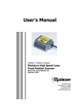
V500-LPN5627/V500-LPR5627 Raster
Miniature High Speed Laser/
Fixed Position Scanner
User Manual
iv
.
OMRON Electronics LLC 2003
All rights reserved. No part of this publication may be reproduced, stored in a retrieval system, or transmitted, in any form, or
by any means, mechanical, electronic, photocopying, recording, or otherwise, without the prior written permission of
OMRON.
No patent liability is assumed with respect to the use of the information contained herein. Moreover, because OMRON is constantly striving to improve its high-quality products, the information contained in this manual is subject to change without
notice. Every precaution has been taken in the preparation of this manual. Nevertheless, OMRON assumes no responsibility
for errors or omissions. Neither is any liability assumed for damages resulting from the use of the information contained in
this publication.
v
Terms and Conditions of Sale
1. Offer; Acceptance. These terms and conditions (these "Terms") are
deemed part of all quotations, acknowledgments, invoices, purchase orders
and other documents, whether electronic or in writing, relating to the sale of
goods or services (collectively, the "Goods") by Omron Electronics LLC
("Seller"). Seller hereby objects to any terms or conditions proposed in
Buyer's purchase order or other documents which are inconsistent with, or
in addition to, these Terms.
2. Prices. All prices stated are current, subject to change without notice by
Seller. Buyer agrees to pay the price in effect at time of shipment.
3. Discounts. Cash discounts, if any, will apply only on the net amount of
invoices sent to Buyer after deducting transportation charges, taxes and
duties, and will be allowed only if (i) the invoice is paid according to Seller's
payment terms and (ii) Buyer has no past due amounts owing to Seller.
4. Interest. Seller, at its option, may charge Buyer 1-1/2% interest per month
or the maximum legal rate, whichever is less, on any balance not paid
within the stated terms.
5. Currencies. If the prices quoted herein are in a currency other than U.S.
dollars, Buyer shall make remittance to Seller at the then current exchange
rate most favorable to Seller and which is available on the due date; provided that if remittance is not made when due, Buyer will convert the
amount to U.S. dollars at the then current exchange rate most favorable to
Seller available during the period between the due date and the date remittance is actually made.
6. Governmental Approvals. Buyer shall be responsible for, and shall bear all
costs involved in, obtaining any government approvals required for the
importation or sale of the Goods.
7. Taxes. All taxes, duties and other governmental charges (other than general
real property and income taxes), including any interest or penalties thereon,
imposed directly or indirectly on Seller or required to be collected directly or
indirectly by Seller for the manufacture, production, sale, delivery, importation, consumption or use of the Goods sold hereunder (including customs
duties and sales, excise, use, turnover and license taxes) shall be charged
to and remitted by Buyer to Seller.
8. Financial. If the financial position of Buyer at any time becomes unsatisfactory to Seller, Seller reserves the right to stop shipments or require satisfactory security or payment in advance. If Buyer fails to make payment or
otherwise comply with these Terms or any related agreement, Seller may
(without liability and in addition to other remedies) cancel any unshipped
portion of Goods sold hereunder and stop any Goods in transit until Buyer
pays all amounts, including amounts payable hereunder, whether or not
then due, which are owing to it by Buyer. Buyer shall in any event remain
liable for all unpaid accounts.
9. Cancellation; Etc. Orders are not subject to rescheduling or cancellation
unless Buyer indemnifies Seller fully against all costs or expenses arising in
connection therewith.
10. Force Majeure. Seller shall not be liable for any delay or failure in delivery
resulting from causes beyond its control, including earthquakes, fires,
floods, strikes or other labor disputes, shortage of labor or materials, accidents to machinery, acts of sabotage, riots, delay in or lack of transportation
or the requirements of any government authority.
11. Shipping; Delivery. Unless otherwise expressly agreed in writing by Seller:
a. Shipments shall be by a carrier selected by Seller;
b. Such carrier shall act as the agent of Buyer and delivery to such carrier
shall constitute delivery to Buyer;
c. All sales and shipments of Goods shall be FOB shipping point (unless
otherwise stated in writing by Seller), at which point title to and all risk of
loss of the Goods shall pass from Seller to Buyer, provided that Seller
shall retain a security interest in the Goods until the full purchase price is
paid by Buyer;
d. Seller may over or under ship by up to 3% of the scheduled quantity.
Exact quantity orders will be accepted at a 5% unit price premium.
e. Delivery and shipping dates are estimates only.
f. Seller will package Goods as it deems proper for protection against
normal handling and extra charges apply to special conditions.
vi
12. Claims. Any claim by Buyer against Seller for shortage or damage to the
Goods occurring before delivery to the carrier must be presented in writing
to Seller within 30 days of receipt of shipment and include the original transportation bill signed by the carrier noting that the carrier received the Goods
from Seller in the condition claimed.
13. Warranties. (a) Exclusive Warranty. Seller's exclusive warranty is that
the Goods will be free from defects in materials and workmanship for
a period of twelve months from the date of sale by Seller. Seller disclaims all other warranties, express or implied. (b) Limitations.
SELLER MAKES NO WARRANTY OR REPRESENTATION, EXPRESS
OR IMPLIED, ABOUT NON-INFRINGEMENT, MERCHANTABILITY OR
FITNESS FOR A PARTICULAR PURPOSE OF THE GOODS. BUYER
ACKNOWLEDGES THAT IT ALONE HAS DETERMINED THAT THE
GOODS WILL SUITABLY MEET THE REQUIREMENTS OF THEIR
INTENDED USE. Seller further disclaims all warranties and responsibility of any type for claims or expenses based on infringement by the
Goods or otherwise of any intellectual property right. (c) Buyer Remedy. Seller's sole obligation hereunder shall be to replace (in the form
originally shipped with Buyer responsible for labor charges for
removal or replacement thereof) the non-complying Good or, at
Seller's election, to repay or credit Buyer an amount equal to the purchase price of the Good; provided that in no event shall Seller be
responsible for warranty, repair, indemnity or any other claims or
expenses regarding the Goods unless Seller's analysis confirms that
the Goods were properly handled, stored, installed and maintained
and not subject to contamination, abuse, misuse or inappropriate
modification. Return of any goods by Buyer must be approved in writing
by Seller before shipment.
14. Damage Limits; Etc. SELLER SHALL NOT BE LIABLE FOR SPECIAL,
INDIRECT OR CONSEQUENTIAL DAMAGES, LOSS OF PROFITS OR
PRODUCTION OR COMMERCIAL LOSS IN ANY WAY CONNECTED
WITH THE GOODS, WHETHER SUCH CLAIM IS BASED IN CONTRACT,
WARRANTY, NEGLIGENCE OR STRICT LIABILITY. Further, in no
event shall liability of Seller exceed the individual price of the Good
on which liability is asserted.
15. Indemnities. Buyer shall indemnify and hold harmless Seller, its affiliates
and its employees from and against all liabilities, losses, claims, costs and
expenses (including attorney's fees and expenses) related to any claim,
investigation, litigation or proceeding (whether or not Seller is a party)
which arises or is alleged to arise from Buyer's acts or omissions under
these Terms or in any way with respect to the Goods. Without limiting the
foregoing, Buyer (at its own expense) shall indemnify and hold harmless
Seller and defend or settle any action brought against Seller to the extent
that it is based on a claim that any Good made to Buyer specifications
infringed intellectual property rights of another party.
16. Property; Confidentiality. The intellectual property embodied in the Goods
is the exclusive property of Seller and its affiliates and Buyer shall not
attempt to duplicate it in any way without the written permission of Seller.
Notwithstanding any charges to Buyer for engineering or tooling, all engineering and tooling shall remain the exclusive property of Seller. All information and materials supplied by Seller to Buyer relating to the Goods are
confidential and proprietary, and Buyer shall limit distribution thereof to its
trusted employees and strictly prevent disclosure to any third party.
17. Miscellaneous. (a) Waiver. No failure or delay by Seller in exercising any
right and no course of dealing between Buyer and Seller shall operate as a
waiver of rights by Seller. (b) Assignment. Buyer may not assign its rights
hereunder without Seller's written consent. (c) Law. These Terms are governed by Illinois law (without regard to conflict of law principles). Federal
and state courts in Illinois shall have exclusive jurisdiction for any dispute
hereunder. (d) Amendment. These Terms constitute the entire agreement
between Buyer and Seller relating to the Goods, and no provision may be
changed or waived unless in writing signed by the parties. (e) Severability.
If any provision hereof is rendered ineffective or invalid, such provision shall
not invalidate any other provision. (f) Setoff. All claims hereunder by Seller
are subject to setoff by Seller for any counterclaim arising out of any transaction with Buyer. (g) Definitions. As used herein, "including" means
"including without limitation.”
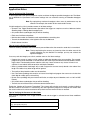
PRECAUTIONS
This section provides general precautions for using the V500 Bar Code Reader.
The information contained in this section is important for the safe and reliable application of the V500 Bar Code
Reader. You must read this section and understand the information contained before attempting to set up or operate
a Bar Code Reader.
1
2
3
Intended Audience . . . . . . . . . . . . . . . . . . . . . . . . . . . . . . . . . . . . . . . . . . . . .
General Precautions . . . . . . . . . . . . . . . . . . . . . . . . . . . . . . . . . . . . . . . . . . . .
Application Precautions . . . . . . . . . . . . . . . . . . . . . . . . . . . . . . . . . . . . . . . . .
viii
viii
viii
vii
1
Intended Audience
1
Intended Audience
This manual is intended for the following personnel, who must also have
knowledge of electrical systems (an electrical engineer or the equivalent).
• Personnel in charge of installing automation systems.
• Personnel in charge of designing automation systems.
• Personnel in charge of managing automation systems and facilities.
2
General Precautions
The user must operate the V500 Bar Code Reader according to the
performance specifications described in the operation manuals.
Please use particular care before using the V500 Bar Code Reader under
conditions which are not described in the manual or applying the V500 Bar
Code Reader to nuclear control systems, railroad systems, aviation systems,
vehicles, combustion systems, medical equipment, amusement machines,
safety equipment, and other systems, machines, and equipment that may
have a serious influence on lives and property if used improperly.
Make sure that the ratings and performance characteristics of the V500 Bar
Code Reader are sufficient for the systems, machines, and equipment, and be
sure to provide the systems, machines, and equipment with double safety
mechanisms.
This manual provides information for installing and operating OMRON V500
Bar Code Readers. Be sure to read this manual before operation and keep
this manual close at hand for reference during operation.
!WARNING It is extremely important that a V500 Bar Code Reader be used for the specified purpose and under the specified conditions, especially in applications that
can directly or indirectly affect human life.
3
Application Precautions
!WARNING Do not touch the terminals while the power is ON. Doing so may cause an
electric shock.
!WARNING It may be necessary to install a power supply breaker to turn OFF the power
supply before working on the V500 Bar Code Reader. Not turning OFF the
power supply may result in electrical shock.
!WARNING Do not allow metal fragments or lead wire scraps to fall inside the V500 Bar
Code Reader. These may cause electric shock, fire, or malfunction.
!WARNING Do not use the V500 Bar Code Reader in flammable and explosive gas atmospheres. There is danger of explosion.
!WARNING Never disassemble, repair, or modify the V500 Bar Code Reader. Doing so
may cause electric shock, fire or malfunction.
viii
Application Precautions
3
Observe the following precautions when using the V500 Bar Code Reader.
• Use and store the V500 Bar Code Reader within the specified temperature and humidity ranges. If there is a possibility of the ambient temperature rising to a temperature above the specified temperature range, take
steps, such as installing fans, to cool the V500 Bar Code Reader. If the
V500 Bar Code Reader is installed incorrectly, heat will build up inside,
shortening the life of the V500 Bar Code Reader. If heat buildup is a problem, use forced cooling, e.g., install a cooling fan.
• Do not touch the patterns or components on a board with your bare
hands. Hold it by the case.
• To allow heat to escape, do not block the area around the V500 Bar Code
Reader. (Ensure that enough space is left for the heat to escape.) Do not
block the ventilation holes on the casing.
• Use the V500 Bar Code Reader within the specified power supply voltage
and rated load ranges.
• Wire properly using the correct terminal polarity.
• Make sure that the rated voltage is reached within 2 seconds after the
power supply is turned ON.
• Attach a surge suppressor or noise filter to peripheral devices that generate noise (in particular, motors, transformers, solenoids, magnetic coils or
other equipment that have an inductance component). When mounting a
noise filter on the power supply, be sure to first check the filter's voltage
and current capacity, and then mount the filter as close as possible to the
V500 Bar Code Reader. Allow as much space as possible between the
V500 Bar Code Reader and devices that generate powerful highfrequency noise (e.g., high-frequency welders, high-frequency sewing
machines) or surges.
• To reduce induction noise, separate the high-voltage or large-current
power lines from other lines, and avoid parallel or common wiring with the
power lines when you are wiring to the terminals. We recommend using
separating pipes, ducts, or shielded lines.
• Install a switch or circuit breaker in a location easily accessible to the
operator and label it appropriately.
• Do not use the V500 Bar Code Reader in the following places:
• Places subject to dust or corrosive gases (in particular, sulfide gas and
ammonia gas)
• Places subject to high humidity, condensation or freezing
• Places subject to direct sunlight
• Places subject to vibration and large shocks
• Places subject to splashing liquid or oily atmosphere
• Places directly subject to heat radiated from heating equipment
• Places subject to intense temperature changes
• Cleaning: Do not use paint thinner or the equivalent. Use standard grade
alcohol to clean the V500 Bar Code Reader.
ix
Application Precautions
x
3
Table of Contents
Section 1: Introduction and Getting
Started
Section 4: Configuring the Scanner
Product Overview ..............................................3
Default Setting ................................................ 17
Quick Start-Up Procedure .................................3
Configuring the Scanner ................................. 17
Section 2: Technical Specifications
Section 5: Application Engineering
Support
Physical Specifications ......................................5
Common Causes of Poor Performance .......... 19
Symbologies Supported ....................................5
Optical Specification ..........................................5
Pitch...................................................................6
Skew ..................................................................6
Tilt (rotation) ..................................................... 6
Curvature...........................................................7
Section 6: Laser Labeling.................... 21
Section 7: Service and
Maintenance .............................................. 23
Appendix A: How to Program the
Scanner ....................................................... 25
V500-LPR5627 Raster Pattern......................... 7
Electrical Specification.......................................8
RS-232C Communications Specifications.........8
Connector Pin Outs ...........................................8
Environmental Specifications ............................9
Ordering Information..........................................9
Section 3: Positioning the Scanner
Achieving Optimum Performance ....................11
Measuring Scanner Performance ....................13
The Read Rate Test.........................................13
Tips for Achieving High Throughput ................14
Appendix B: Computer Programming
Commands ................................................ 27
Appendix C: Bar Code Programming
Commands ................................................ 33
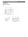
Appendix D: Dimensional
Drawings .................................................... 67
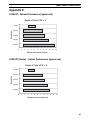
Appendix E: Optical Performance ... 69
Appendix F: PLC/Touchscreen
Connection Examples ........................... 71
Tips for Insuring Highest Data Integrity ...........14
Tips for Verifying the Presence
of a Bar Code ..................................................14
1
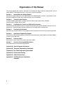
Organization of this Manual
This manual provides the necessary instructions for installing and using the Omron V500-LPN5627 and the
V500-LPR5627 Fixed Position Scanners. The manual is organized as follows:
Section 1:
Introduction and Getting Started
Describes the general operation of the V500-LPN5627 and V5000-LPR5627 scanners. Also provides a Quick
Start-Up Procedure that allows you to begin using the scanner immediately.
Section 2:
Technical Specifications
Provides complete specifications, including mechanical details, optical performance, RS-232C
communications and other technical data.
Section 3:
Positioning the Scanner for Optimum Performance
Provides detailed instructions and tips for mounting and positioning the scanning to obtain the best scanning
performance. Application Notes describe guidelines for maximizing specific characteristics.
Section 4:
Configuring the Scanner
Describes how various parameters can be programmed to customize the scanner for your specific application.
Section 5:
Application Engineering Support
Discusses the most common questions and concerns when adapting the V500-LPN5627 and V500-LPR5627
scanners in your application.
Section 6:
Scanner Labels
Discusses the various labels on the product required by CDRH.
Section 7:
Scanner Servicing and Maintenance
Discusses maintenance and cleaning procedures.
Appendix A: How to Program the Scanner
Appendix B: Computer Programming Commands
Appendix C: Bar Code Programming Commands
Appendix D: Dimensional Drawing
Appendix E: Optical Performance
Appendix F: PLC/Touchscreen Connection
Examples
2
Section 1 - Introduction and Getting Started
V500-LPN5627/V500-LPR5627
Section 1
Introduction and Getting Started
Product Overview
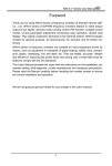
The V500-LPN5627 and V500-LPR5627 (Raster) Fixed Position Scanners are miniature, 500 scan per second,
laser bar code readers designed to be easily incorporated into host equipment. The high scan speed and small
physical size make the scanner easy to integrate into any hardware design. Durability and reliability are
assured.
Advanced microprocessor technology coupled with Omron’s proven decoding algorithms result in high speed
operation with superior accuracy. The scanners are fully programmable allowing the user to customize parameters including changing communication settings, selecting symbologies, adding prefixes and appending
suffixes. Programmable settings can be downloaded from the host CPU or computer directly to the scanner.
The scanners are encased in compact, rugged metal enclosures. The compact size permits installation in the
tightest areas allowing great flexibility in mounting and positioning the scanner for optimum performance.
Quick Start-Up Procedure for Computer Connections
This section is for those who wish to start using the scanner before reading the complete manual. Only a few
steps are needed to make the scanner operable.
• Connect the board to a DB9 serial port, such as COM 1 on you PC.
• Be sure your PC or host device is running an application such as HyperTerminal that will accept serial
input.
• The default communications parameters of the scanner are 9600 baud, 1 Start/Stop Bit, 8 Data bits, No
Parity, No Handshaking, No Flow Control. See Users Manual for details on establishing or changing
communications parameters.
• Plug the 5 VDC power supply into the jack on the connector.
• There is a trigger test button on the scanner.
That’s it. Your PC and the scanner should now communicate.
To verify that the scanner and the PC are communicating properly, send the following command from your PC
keyboard to activate the scanner’s buzzer.
Send the command:
<Escape> V5 <Carriage Return>
Note Be sure to use capital letters, e.g. “V5”, not “v5”. The buzzer should sound,
indicating that good communications have been established.
To test the scanner, press the trigger test button on the scanner itself. A red laser light will be visible. Do not
stare into the laser light.
This Quick Start-Up procedure will get you started. However, to best understand the full capabilities of this
scanner, you should read the complete manual.
3
Section 1 - Introduction and Getting Started
4
V500-LPN5627/V500-LPR5627
Section 2 - Technical Specifications
V500-LPN5627/V500-LPR5627
Section 2
Technical Specifications
Physical Specifications
Case Material
Zinc-die cast
Dimensions
1.9 x 1.5 x 0.9 in (WxDxH) (47.4 x 37.2 x 23 mm)
Weight
2.9 oz (80 grams) w/o cable
Cable length
6.5 feet (2000 mm)
Connector
9-pin Male MiniDIN Connector on “-C” units, 9-pin Female on “-P” units
Mounting
2 threaded (M-3) mounting holes
(not to extend more than 3 mm into the case)
Symbologies Supported
• Codabar (NW-7)
• Code 39
• Code 93
• Code 128
• Industrial 2 of 5 Interleaved 2 of 5
• MSI / Plessey
• WPC (UPC / EAN / JAN)
• IATA
Optical Specifications
Scan rate
500 scans per second ± 10%
Light source
650 ±10nm visible laser diode
Narrow Bar Resolution
6 mil (0.15 mm) at 0.9 PCS
Minimum PCS
0.45 (min. background reflectance of 70%)
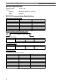
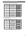
Reading Distances* V500-LPN5627
Bar Code Density
Near Distance
40 mil (1.00 mm)
2.3 in.
20 mil (0.50 mm)
2.3 in.
10 mil (0.25 mm)
2.3 in.
6 mil (0.15 mm)
3.5 in.
Far Distance
12.6 in.
10.8 in.
7.5 in.
4.7 in.
* Measured from edge of scanner.
Reading Distances* V500-LPR5627 Raster
Bar Code Density
Near Distance
40 mil (1.00 mm)
2.3 in.
20 mil (0.50 mm)
2.3 in.
10 mil (0.25 mm)
2.3 in.
6 mil (0.15 mm)
3.5 in.
Far Distance
10.6 in.
9.1 in.
6.7 in.
4.3 in.
* Measured from edge of scanner.
5
Section 2 - Technical Specifications
V500-LPN5627/V500-LPR5627
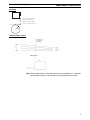
Pitch
Hatched No-Read
Specular Zone
+5˚
Height
of
Barcode
-10˚
Note Recommended operation (α) at ± 60° or less. Avoid specular reflection in the
dead zone (hatched).
Skew
Note Recommended operation (β) ± 25°.
Tilt (Rotation)
θ
θ
Note Recommended operation (θ) ± 25° (barcode aspect ratio allowing laser to
cover all bars).
6
Section 2 - Technical Specifications
V500-LPN5627/V500-LPR5627
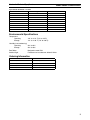
Curvature
H
Jan 13: R = 20 mm (0.8 in) or
Jan 8: R = 15 mm (0.6 in)
Where: PCs 0.9, h = 100 mm,
Pitch = 15˚, Skew = 0˚, Tilt = 0˚.
R
LPR5627 Raster Pattern
Note Raster sweep pattern as seen from front of scanner. Subtends a 1° angle from
top to bottom of raster, (at the centerline) as measured from the scanner.
7
Section 2 - Technical Specifications
V500-LPN5627/V500-LPR5627
Electrical Specifications
+5 VDC ± 10%
Operating Voltage
Current:
Operating
150 mA idle; 350 mA max. (laser ON)
Surge
2.5 A max.
RS-232C Communications Specifications
RS232 Data Transmission Format
Parameter
Default
Asynchronous
1 bit
1 bit
8 bits
None
9600 Baud
None
Timing
No. of start bits
No. of stop bits
No. of data bits
Parity
Baud Rate
Handshaking
Optional Settings
--1 or 2 bits
7 or 8 bits
Odd/Even/None
300 to 38,400 Baud
Hardware/Software/None
RS-232C Transmit / Receive Character Format
TXD/
RXD
Start
Bit
7 or 8
Data Bits
LSB
Parity
Bit
MSB
Stop
Bit
RS-232C Data Format
Transmit
Receive
Decoded Data
Command
Command
ESC
STX
CR
CR
ETX
RS-232C Signal Level
Signal Name
TXD
RXD
In/Out
Out
In
Mark/Off
-5 to -15
-3 to -15
Space/On
+5 to +15
+3 to +15
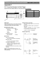
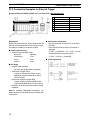
Connector Pin-outs
9 pin Male Mini-Din Connector “-C” Units
Pin No.
1
2*
3*
4
5
6
7
8
9
Signal
TXD
RXD
DSR
Signal ground
DTR
SRTS
CTS
-
Direction
Output
Input
Output
Input
-
Note * NPN open collector, rated at 24 VDC, 30 mA maximum.
8
Section 2 - Technical Specifications
9 pin Female Connector “-P” Units
Pin No.
Signal
1
2
RXD
3
TXD
4
RTS
5
CTS
6
+5V
7
8
9
Signal ground
V500-LPN5627/V500-LPR5627
Direction
Input
Output
Connected to 5
Connected to 4
Input
-
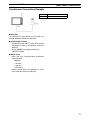
Environmental Specifications
Temperature
Operating
+32° to +113° F (0° to +45°C)
Storage
+14° to +140° F (-10° to +60°C)
Humidity (non-condensing)
Operating
20% to 85%
Storage
20% to 90%
Dust/Water
Designed to meet IP54
Ambient Light
Fluorescent or incandescent: below 5 kilolux
Ordering Information
Part No.
V500-LPN5627-C
V500-LPN5627-P
V500-LPR5627-C
V500-LPR5627-P
Model
Linear, computer
Linear, Omron PLC/Touchscreen
Raster, computer
Raster, Omron PLC/Touchscreen
9
Section 2 - Technical Specifications
10
V500-LPN5627/V500-LPR5627
Section 3 - Positioning the Scanner
V500-LPN5627/V500-LPR5627
Section 3
Positioning the Scanner
Achieving Optimum Performance
Three items greatly impact performance:
• Distance (from the scan window) to the bar code
• Spectral reflection
• Quality of Bar Code labels
1) Distance to the Bar Code
The operation of the scanner is similar to a camera. If you photograph an object that is out of focus, the resulting picture will be blurry. The same is true with the scanner. If the bar code label is out of focus, the scanner
may have difficulty decoding what appears to be fuzzy bars and spaces.
Focal Distance
Ideally, the distance from the window of the scanner to the bar code label should be equal to the focal distance
of the scanner. For the V500-LPN5627 / V500-LPR5627 fixed position scanners, the nominal focal distance is
approximately 4.0 in. from the front edge of the scanner.
Depth-of-Field
Just as with a camera, the scanner has a depth-of-field. It can read bar codes that are not precisely at the focal
distance - maybe a little closer, or a little farther away. However, if the bar code label is positioned too far from
the focal distance, the scanner may not be able to successfully decode it.
The depth-of-field varies based on the density of the bar code, i.e., the thickness of the bars. Very high density
bar codes (which have very narrow bars) are readable over a much shorter distance range than low density bar
codes with larger bars.
The following table shows the depth-of-field specifications (closest to farthest reading distances) for the
V500-LPN5627 / V500-LPR5627 scanners. The actual performance may differ slightly from unit to unit. Also,
it is important to note that this data was measured under ideal conditions using high quality bar code labels. In
a “real world” environment the conditions will not be as ideal. Therefore, the best practice is to position the
scanner at the center of the depth-of-field rather than at the extremes of its depth-of-field.
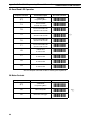
Depth-of Field* V500-LPN5627
Bar Code Density
40 mil (1.00 mm)
20 mil (0.50 mm)
10 mil (0.25 mm)
6 mil (0.15 mm)
Near Distance
2.3 in.
2.3 in.
2.3 in.
3.5 in.
Far Distance
12.6 in.
10.8 in.
7.0 in.
4.7 in.
* Measured from front edge of scanner.
11
Section 3 - Positioning the Scanner
V500-LPN5627/V500-LPR5627
Readable Bar Code Width V500-LPN5627 / V500-LPR5627
Field-of-View Specification Based Upon 40 Degree Sweep
Distance from Window
2.0 in.
4.0 in.
8.0 in.
12.0 in.
Max. Width
2.0 in.
3.5 in.
6.4 in.
9.3 in.
The table above shows the field-of-view at various distances from the window. The field-of-view is the
maximum width that the scanner is capable of reading. It is the distance from the left edge of the view to the
right edge. A bar code label positioned anywhere within this field-of-view can be decoded. The field-of-view is
also a measure of the widest bar code label that can be read. Remember: The width of a bar code label
includes not only the bars and spaces but also the required white space (quiet zone) on each end.
Good design policy is to position the barcode at the midpoint of the scanner’s depth-of-field and at the center of
the field-of-view. Do not position it near the extremes of the reading range.
Comparable depth-of-field parameters for the LPR5627 are the following:
Depth-of-field* V500-LPR5627- Raster
Bar Code Distance
40 mil (1.00 mm)
20 mil (0.50 mm)
10 mil (0.25 mm)
6 mil (0.15 mm)
Near Distance
2.3 in.
2.3 in.
2.3 in.
3.5 in.
Far Distance
10.6 in.
9.1 in.
6.7 in.
4.3 in.
* Measured from front edge of scanner.
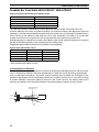
2) Avoiding Specular Reflection
Do not position the scanner at an angle that causes the laser light to be reflected directly back into the scanner.
This is called specular reflection. Too much reflected light can “blind” the scanner preventing a good decode.
If the bar code label is located on a flat surface, specular reflectivity occurs between 0 to 10 degrees off perpendicular (See diagram). If the bar code label is located on a cylindrical surface, such as a test tube, the angle
of specular reflection is measured tangent to the curve. If the curved surface is also moving, there may be
more than one position causing specular reflection. The following diagram indicates the area to avoid:
Hatched No-Read
Specular Zone
+5˚
Height
of
barcode
-10˚
12
Section 3 - Positioning the Scanner
V500-LPN5627/V500-LPR5627
3) Quality Bar Code Labels
The quality of the bar code label can affect the scanning performance. Poor quality labels are more difficult to
decode and may result in non-reads or potential misreads. The bar code label should be printed to specifications. This means that the bars are printed within spec, with the correct widths, no ink spread, crisp edges and
no voids. There should be a sufficient quiet zone on both ends of the bar code label. For best results, the paper
or label stock should have a matte finish to diffuse light. The print contrast signal (which is a comparison of the
reflectance of the bars and the background stock) should be as high as practical.
Measuring Scanner Performance
Two methods are helpful in determining the optimum position of the scanner. The first method is to program the
scanner for Trigger Disable and Continuous Read modes. The scanner will always be on and will
continuously read the same bar code. Since the buzzer sounds each time the bar code is read, the sound of
the buzzer can be used like a “Geiger counter.” As the position of the scanner changes the sound of the buzzer
will change. The buzzer sound will be loudest and most continuous at the best reading positions.
The Read Rate Test
The second method, the Read Rate Test, provides a mathematical calculation of scanning performance. In this
test the scanner scans a bar code 500 times and then calculates the number of those scans that resulted in a
good decode. That number, expressed as a percentage, will be transmitted to the host. For example, 93%
means that the scanner decoded the bar code symbol 93 times out of the 500 scan attempts. By performing
the Read Rate Test with the scanner mounted in various positions you can determine which of those locations
results in the best performance.
How to perform the Read Rate Test
Perform the following steps after you have correctly configured communications to the computer via your
RS-232C port and power is made available to the scanner:
Send the command: <Escape> U8 <Carriage Return>
Note Be sure to use capital letters, e.g. “U8,” not “u8.”
The scanner will read the barcode continuously and will display the ratio of the number of successful reads to
the total number of attempts.
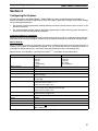
The printout on the screen will appear as follows:
(Example)
500d OK 93.5%
CODE-39 TEST
The number in the upper left indicates the number of times the decoder ran while scanning at 500 scans per
second. The number can be lower than 500 when reading noisy barcodes. The upper right percentage indicates the ratio of the number of successful reads to the total number of attempts. By positioning the scanner at
the optimal distance from the barcode with the correct orientation and with a grade-A quality barcode, readings
of 95% or higher are expected. Reset the scanner after testing.
13
Section 3 - Positioning the Scanner
V500-LPN5627/V500-LPR5627
Application Notes
Tips for Achieving High Throughput
In some applications your primary objective may be to achieve the highest possible throughput rate. The following list identifies the parameters and scanner settings that can maximize scanning and decode throughput
speed.
Note By emphasizing maximum throughput, other areas of performance may be
affected. For example, the number of non-reads could increase.
If high throughput is critical, consider some or all of these settings:
• Operate in the Trigger Disabled mode. Operation of the trigger can require as much as 200 msec before
decoding begins, slowing down throughput rate.
• Only enable those symbologies that you will be decoding.
• Eliminate all suffixes and prefixes.
• Minimize the number of redundant reads required before transmitting data.
• Transmit the decoded data at the highest baud rate, 38,400 baud.
• Disable buzzer functions.
Tips for Insuring Highest Data Integrity
There are several parameters that can enhance your confidence that the correct bar code data is transmitted.
Note That by emphasizing the accuracy and security of the data other areas of the
scanner operation may be affected. For example, you may not achieve the
highest throughput.
If accuracy and data integrity are critical, consider some or all of these settings:
• Program the scanner to require a high number of redundant decodes prior to transmitting. For example,
program the scanner to decode a bar code exactly the same way three consecutive times before transmitting the data. Then decoding the bar code the same way 2 out of 3 times or any 3 out of 4 times is not
sufficient. It must obtain three consecutive and identical decodes.
• Utilize a predetermined, fixed-length of bar code. Program the scanner to only decode a bar code of that
length. Bar codes of any other length will be ignored.
• The quality of the printed bar code must be excellent.
• Use a bar code symbology that contains an internal check digit and program the scanner to calculate that
check digit for validity prior to transmitting.
• Do not use a symbology with poor internal verification, or subject to partial decodes, such as 2 of 5 or MSI/
Plessey.
• Only enable those symbologies that you will be decoding.
• Transmit data at low baud rates to minimize communication errors.
Enable the “Number of Characters Transmitted.” The scanner will calculate and transmit a number indicating
the total number of characters it is transmitting. Your host application program can compare this number with
the actual number of characters received to verify that the correct amount of data is received.
Tips for Verifying the Presence of a Bar Code
If the scanner is operated in the “trigger enabled” mode and the trigger is activated, one of three conditions
may occur.
A bar code is scanned and decoded
Decoded data is transmitted
A bar code is scanned but is not decoded
(e.g., print quality was poor)
No data is transmitted
No bar code is present
No data is transmitted
14
Section 3 - Positioning the Scanner
V500-LPN5627/V500-LPR5627
In some applications, when no data is transmitted, it may be important to know why. Was there a bar code
present that could not be decoded, or was no bar code present at all?
This requirement is common in applications such as automated blood analysis equipment. Test tubes containing blood samples from many different people are loaded into a rack for automatic analysis. The bar code on
each tube ties that sample and the results back to a specific individual. If no bar code data is transmitted it is
critical to understand the reason.
Your Omron scanner, when operated in the Trigger Enabled mode, can be programmed to transmit an error
message indicating whether or not a bar code was present. The following table shows the message that will be
transmitted for each condition.
Presence/Absence of bar code
Bar code was present and correctly decoded
Scanner Transmits
Decoded Data
No bar code was present
<STX> “?” <ETX>
Bar code was present but could not be decoded
<STX> “>” <ETX>
15
Section 3 - Positioning the Scanner
16
V500-LPN5627/V500-LPR5627
Section 4 - Configuring the Scanner
V500-LPN5627/V500-LPR5627
Section 4
Configuring the Scanner
Since the operation of the V500-LPN5627 / V500-LPR5627 scanners are microprocessor controlled, it is
possible to modify or program its operation to match your specific application. Changes in parameter settings
can be accomplished two ways.
1. The scanner can be programmed by sending software instructions from the host PC to the scanner via the
RS-232C connection.
2. The second method employs specially designed programming bar codes. Scanning these bar codes instructs the scanner to modify specific parameters.
Programming Menus & Commands
Appendix A contains full instructions on how to configure the scanner as well as a complete listing of the computer commands and programming bar codes that are available to customize the scanner for your application.
Default Settings
When you modify or change any parameters, the scanner can be programmed to retain the new parameter in
memory, even if power is interrupted or terminated. If for any reason the scanner is instructed to return all
parameters to default settings (U1), it will return to the default settings shown in the following table.
%) throughout the bar codes menus.
Default settings are indicated by a pointing hand symbol (
Parameter
RS-232C Communications
“-C” Factory Default Setting
9600 baud
8 data bits
1 stop bit
No parity
No handshaking
Trigger Function
Read Mode
No. of Redundant Decodes
UPC-A (13 digits)
Enabled
Multiple Read Mode
Read twice before transmitting
Add leading zero
Enable check digit
UPC-E (7 digits)
Add leading zero
No check digit
Do not calculate check digit/Transmit check digit
Enable start/stop characters (*.....*)
Disable character length of one
Code 39
Codabar
2 of 5
Fixed length of bar code only
Buzzer
Positive bar codes only
Error indications
Print quality adjustment
“-P” Factory Default Settings
9600 baud
7 data bits
2 stop bits
Even parity
No handshaking
Enable start/stop characters as abcd/abcd
Do not calculate check digit/Transmit check digit
Disable character length of one
Do not calculate check digit
Disable characters length of two
Disabled
Enabled
Disabled (Both positive and negative barcodes)
Do not transmit error code
Output from Low or High analog gain
1 MHz sampling rate
17
Section 4 - Configuring the Scanner
18
V500-LPN5627/V500-LPR5627
Section 5 - Application Engineering Support
V500-LPN5627/V500-LPR5627
Section 5
Application Engineering Support
Technical Assistance and Support
Omron is eager to help you integrate the V500-LPN5627 / V500-LPR5627 scanner into your application. Our
technical support staff is available to answer any questions or work with you to adapt the scanner to your specific situation. We are happy to answer your questions, assist in configuring and positioning the scanner for
optimum operation, and help resolve any problems you encounter. Call us at (800) 556-6766.
Common Causes of Poor Performance
The most common reasons for poor scanning performance are listed below:
• Bar codes are not positioned at the focal distance of the scanner.
• Specular reflection is impacting the scanner. Change the angle/position of the scanner or the bar code.
• Poor quality of printed bar codes. Bar codes are out of specification.
• The paper on which the bar code is printed is highly reflective or has a glossy finish causing light to be
reflected into the scanner.
• The distance from the scanner to the bar code is not suitable for the density of the bar code. Or the density
of the bar code is beyond the scanners capability. If the red illuminating light of the scanner is not on, the
scanner may be in the “Trigger Enable” mode expecting a trigger signal.
19
Section 5 - Application Engineering Support
20
V500-LPN5627/V500-LPR5627
Section 6 - Scanner Labeling
V500-LPN5627/V500-LPR5627
Section 6
Scanner Labeling
CDRH Class II Laser Device
V500-LPN5627 / V500-LPR5627 scanners comply with Center for Devices and Radiological Health (CDRH)
regulations 21, CFR Subchapter J. It is classified as a Class II Laser Device.
The V500-LPN5627 / V500-LPR5627 scanners use a low-power visible laser. As with any very bright light
source, such as the sun, you should avoid staring into the light beam. Momentary exposure to a CDRH Class II
laser is not known to be harmful.
A laser safety label is affixed to the scanner as shown.
If the V500-LPN5627 or V500-LPR5627 scanner is incorporated into or interfaced to other equipment, that
equipment should include a laser safety label and a visible indicator that is illuminated whenever laser energy
is being emitted from the scanner. This indicator may remain illuminated when the scanner is powered but the
laser is not emitting energy.
21
Section 6 - Scanner Labeling
22
V500-LPN5627/V500-LPR5627
Section 7 - Scanner Servicing and Maintenance
V500-LPN5627/V500-LPR5627
Section 7
Scanner Servicing and Maintenance
!Caution Use of controls or adjustments or performance of procedures other
than those specified herein may result in hazardous laser light exposure.
The V500-LPN5627 / V500-LPR5627 scanners contain no user adjustable or serviceable parts in the interior of
the scanner. All product service must be performed by Omron. Opening the scanner will void the warranty and
could expose the operator to laser light.
The V500-LPN5627 / V500-LPR5627 are warranted for 1 year including parts and workmanship. If you need
warranty or out-of-warranty repair, first call Omron or your distributor to obtain a Returned Material Authorization (RMA) number. You will be provided a number and shipping instructions.
There is no scheduled maintenance required for the V500-LPN5627 / V500-LPR5627. The scanner can be
cleaned using a water dampened, lint free or lens cloth. Be careful to avoid excessive moisture that would penetrate the housing or obscure the window. While use of cleaning fluids other than water are not recommended,
a neutral detergent or ethanol would be preferred if necessary. Do not use bleach at full or diluted strength as
damage to the painted case and/or window may result.
23
Section 7 - Scanner Servicing and Maintenance
24
V500-LPN5627/V500-LPR5627
Appendix A - Programming the Scanner
V500-LPN5627/V500-LPR5627
Appendix A
Programming the Scanner
Two different methods can be used to program parameters to configure the scanner:
• Programming via Computer Commands
• Programming via special Bar Codes from a menu page
Most parameters can be programmed using either of these two methods. However, there are certain
parameters that are only programmable via the bar code menu.
Programming via Computer Commands
Parameters can be programmed by sending software commands or keyboard strokes from the host computer
to the scanner in the following format:
<ESC> Computer Command <CR>
Note Only upper case letters are recognized, e.g., “AB” not” ab”
Each command normally consists of two characters
Downloading of software commands cannot be “grouped” together. Each
command must be preceded by <ESC> and followed by a <CR>
Parameters programmed by downloaded commands can be stored permanently by transmitting a
“<ESC> Z2 <CR>” command. It is not necessary to send a “Z2” command after each parameter is changed.
One Z2 command will save all changes
Appendix B lists all of the Computer Commands. In Appendix C, Bar Code Programming Menus, the left-hand
column in all menus contains the Computer Command associated with that bar code.
Programming via Bar Codes
Use the following steps to program parameters via the bar code menus:
1. Scan the “Start/End” bar code. This instructs the scanner to enter the Programming Mode. While in this
mode the scanner will beep intermittently.
2. Scan the bar code(s) associated with the desired parameter(s). The scanner will beep when the bar code
is read. Note: because of the close proximity of bar codes on the page, it is important to aim carefully to
ensure that only the desired bar code is scanned.
3. Scan the “Start/End” bar code. This instructs the scanner to exit the Programming Mode.
All the parameters that were scanned are retained in memory and are stored permanently (even if the
scanners is power down) or until they are changed again.
When the scanner is in the Programming Mode, you can change more than one parameter at a time. However,
this may become confusing. Until you be come proficient at programming you may prefer to change only a few
parameters at one time. We recommend that you keep a record of the changes you have made to the scanner.
What if you make a mistake?
Don’t worry. If you are programming the scanner but are unsure of which parameters have been changed, scan
the Reset All Defaults bar code. This bar code returns the scanner to the default settings that were installed in
the factory at the time the product was manufactured. Scanning this bar code erases any change you have
made, including any changes that were made during previous programming.
Reset All Defaults U1 Command (U1).
This command will return all settings to the factory default settings.
We recommend that after you have reset all defaults you also set the commands for No Handshaking (P0), All
Symbologies (A0), and Do Not Transmit Start/Stop Characters (D0) for Code 39.
25
Appendix A - Programming the Scanner
V500-LPN5627/V500-LPR5627
Reset All Defaults
Computer
Command
Function / Description
Z7
START/END Programming Mode
U1
Reset All Defaults
A0
Decodes all Symbologies
P0
No Handshaking
D0
For Code 39: do not transmit start/
stop characters *….*
Z2
Save settings in memory
Z7
START/END Programming Mode
Bar Code Command
-[8-V2-B1-Q1-E1-[3-[8-
Note Appendix C contains all the Bar Code Programming menus
and commands.
26
Appendix B - Computer Programming Commands
V500-LPN5627/V500-LPR5627
Appendix B
Computer Programming Commands
All commands must be preceded by an ‘ESC’ character and be followed by a ‘Carriage Return’ character.
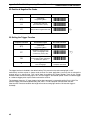
Shaded areas indicate factory default settings.
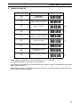
Enable
Disable
Global Defaults
U1
Enable Factory Default Settings
1Y
Clear all prefixes
1Z
Clear all suffixes
P9
Transmit Barcode Pattern Data
U8
Read Rate Test Mode
Z1
Clear all values set by command
Z2
Save all values set by command
Z3
Display software settings & version
no.
Z4
Display prefix/suffix
Enable
Disable
UPC-A (13 Digits) Leading zero &
CD
UPC-A (12 Digits) No leading 0 &
CD
UPC-A (12 Digits) Leading zero &
No CD
UPC-A (11 Digits) No leading 0 & no
CD
E2
E3
E4
E5
E6
UPC-E (8 Digits) Leading 0 & CD
UPC-E (7 Digits) No leading zero &
CD
UPC-E (7 Digits) Leading zero; no
CD
UPC-E (6 Digits) No leading 0 & no
CD
E7
E8
E9
Only
Add
Rmv
A0
Symbology Selection
Enable
Options for UPC
Disable
Options for Code 39
Enable all symbologies
7C
7D
Enable 1 character read
A1
B1
4A
WPC (including add-ons)
C1
C0
Enable Check Digit calculation
A2
B2
4H
Code 39
C2
C3*
Transmit Check Digit
A3
B3
4I
Codabar (NW-7)
D1
D0
A4
B4
4J
2 or 5 Industrial or Interleaved
Transmit start/stop characters
(*…..*)
J7
R7
4K
2 or 5 Industrial
J8
R8
4L
2 or 5 Interleaved
A5
B5
4M
Code 93
A6
B6
4N
Code 128
A7
B7
4O
MSI/Plessey
A8
B8
4P
IATA
J1
R1
4B
UPC (A/E)
J2
R2
4C
UPC (A/E)+2
J3
R3
4D
UPC (A/E)+5
J4
R4
4E
EAN
J5
R5
4F
EAN+2
J6
R6
4G
EAN+5
4Z
Disable all Symbologies
Note Only disable if C1 enabled, otherwise truncate
last digit.
27
Appendix B - Computer Programming Commands
V500-LPN5627/V500-LPR5627
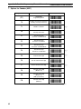
Enable
Disable
Options for Codabar (NW-7)
Prefix
Suffix
Creating a Prefix and/or Suffix
7K
7L
Enable 1 character read
1Y
1Z
Clear all
F0
Do not transmit start/stop
characters
Z4
Z4
Display Prefix/suffix values & length
F1
Transmit start/stop as ABCD/TN*E
F2
Transmit start/stop as abcd/tn*e
F3
Transmit start/stop as ABCD/ABCD
F4
Transmit start/stop as abcd/abcd
F5
F6
Transmit check digit
F7
Do not calculate check digit
F8
Calculate check digit (modulo 10)
F9
Calculate CD (modulo 16) AIM
spec.
FB
Calculate check digit (modulo 7)
Select Symbology for Prefix/Suffix
N1
N6
UPC-A
M0
O0
UPC-A +2 or +5
N2
N7
UPC-E
M1
O1
UPC-E +2 or +5
N3
N8
EAN13
M2
O2
EAN-13 +2 or +5
N4
N9
EAN-8
M3
O3
EAN-8 +2or +5
M4
O4
Code 39
M5
O5
Codabar (NW-7)
Enable
Disable
Options for Interleaved 2 of 5
M6
O6
Industrial 2 of 5
G1
G0
Calculate check digit
M7
O7
Interleaved 2 of 5
G2
G3
Transmit check digit
M8
O8
Code 93
7M
7N
Enable 2 characters
M9
O9
Code 128
D8
D9
IATA
N0
N5
MSI/Plessey
Enable
Disable
Options for IATA
D2
Do not calculate check digit
D3
Calculate CD (CPN + Form +
Serial)
D4
Calculate CD (Form + Serial)
D5
Calculate check digit (all data)
D6
D7
Transmit check digit
Prefix/Suffix of Numeric Characters
Q0
0
thru
thru
Q9
9
Prefix/Suffix of Alpha Characters
0A
A
thru
thru
0Z
Z
Prefix/Suffix of Control Characters
28
1A
STX
1B
ETX
1C
Carriage Return (Default Suffix Character)
1D
Line Feed
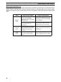
Appendix B - Computer Programming Commands
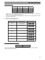
Communications Parameters
K1
300 baud
K2
600 baud
K3
1,200 baud
K4
2,400 baud
K5
4,800 baud
K6
9,600 baud
K7
19,200 baud
K8
38,400 baud
L0
7 Data Bits
L1
8 Data Bits
L2
Parity = None
L3
Parity = Even
L4
Parity = Odd
L5
1 Stop bit
L6
2 Stop bits
Handshaking
V500-LPN5627/V500-LPR5627
Enable
Disable
Enable character length
transmission
3A
2A
UPC-A
3B
2B
UPC-A +2 or +5
3C
2C
UPC-E
3D
2D
UPC-E +2 or +5
3E
2E
EAN13
3F
2F
EAN-13 +2 or +5
3G
2G
EAN-8
3H
2H
EAN-8 +2or +5
3I
2I
Code 39
3J
2J
Codabar (NW-7)
3K
2K
Industrial 2 of 5
3L
2L
Interleaved 2 of 5
3M
2M
Code 93
3N
2N
Code 128
3O
2O
MSI/Plessey
3P
2P
IATA
3Z
2Z
Transmit data length of all
symbologies
Disable Fixed Number of Digits
I0
Unlimited wait for CTS from terminal
I1
100 mS wait for CTS from terminal
I2
200 ms wait for CTS from terminal
Enable
I3
400 mS wait for CTS from terminal
7V
Enable fixation (1st Length)
I4
Unlimited ACK/NAK Timeout delay
7W
Enable fixation (2nd Length)
I5
100 mS ACK/NAK Timeout delay
H0
Disable fixation
I6
500 mS ACK/NAK Timeout delay
H3
I7
1000 mS ACK/NAK Timeout delay
P0
No Handshaking
P1
Busy/Ready
P2
Modem
P3
ACK/NAK
P4
ACK/NAK No buzzer on timeout
P5
No ACK/NAK
H2
Enable 1 digit Code 39 and Codabar
(NW-7) and enable 2 digit 2 of 5
Note For “-P” type units, default communication is 9600, 7, E, 2.
29
Appendix B - Computer Programming Commands
V500-LPN5627/V500-LPR5627
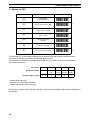
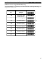
Buzzer Operation
Selecting the Read Mode
S0
Single Read Mode (Trigger must be Enabled,
S8)
S1
Multiple Read Mode
S2
Continuous Read Mode
7H
Does not allow first bar distortion
7I
Allow first bar distortion
7O
Normal scan
T0
Volume = Maximum
T1
Volume = Upper mid-range
T2
Volume = Lower mid-range
T3
Volume = Minimum
V5
Ring buzzer once at 3kHz for 200 mS
V6
Ring buzzer at 3kHz & 2kHz for 200 mS
V7
Ring buzzer at 2kHz & 3kHz for 200 mS
W0
Disable Buzzer
W1
Enable buzzer at 3kHz
W2
Enable buzzer at 3kHz with 2.5kHz interval
Y0
Laser remains ON as long as trigger is pulled
(hardware trigger only)
W3
Enable buzzer at 2kHz with 3kHz interval
Y1
1 second after triggering
W4
Buzzer duration 0.10 sec
Y2
2 second after triggering
W5
Buzzer duration 0.20 sec
Y3
3 second after triggering
W6
Buzzer duration 0.40 sec
Y4
4 second after triggering
W7
Buzzer duration 0.05 sec
Y5
6 second after triggering
W8
Buzzer duration 0.01 sec
Y6
8 second after triggering
Y7
10 second after triggering
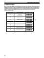
Scanner Timeout (Trigger Enabled Mode)
Redundant Decoding
Positive & Negative Bar Codes
V4
Positive bar codes only
X0
Read bar code once
V2
Both positive and negative bar codes
X1
Read bar code twice before transmitting
X2
Read bar code three times before transmitting
X3
Read bar code four times before transmitting
7R
Read bar code five times before transmitting
7S
Read bar code six times before transmitting
Setting the Trigger Function
S7
Disable the trigger function (Laser On)
S8
Enable the trigger function (Laser OFF until the
trigger is activated )
Z
Activate the trigger; turns the laser ON
Xmit Error (Trigger Enabled Mode only)
30
5E
Do not Xmit error code
5F
Xmit “BR” <CR> for bad read or no read
5G
Xmit <STX> ”>” <ETX> for bad read; <STX>
“?” <ETX> for no read
5H
Xmit “>” <CR> for bad read,”?” <CR> or no read
5I
Transmit “<CAN>” <CR> for bad read or no
read
5J
Xmit “<CAN>”<ETX> for bad read or no read
Appendix B - Computer Programming Commands
V500-LPN5627/V500-LPR5627
Print Quality Adjustment
Motor Control
X4
For lower density, poor print (low gain)
S6
Motor always ON
X5
For high density, good print quality bar code
without voids (high gain)
S5
Motor OFF until trigger
X6
Xmit data from Low or High gain
X7
Xmit data from Low and High gain
Good Read LED Operation
T4
Disable good read LED (GRL)
T8
GRL ON for 0.10 seconds after decode
T5
GRL ON for 0.20 seconds after decode
T6
GRL ON for 0.40 seconds after decode
T7
GRL ON for 0.80 seconds after decode
V0
LED ON Red for 0.40 seconds
V1
LED ON Red for 0.80 seconds
V8
LED ON Green for 0.40 seconds
V9
LED ON Green for 0.80 seconds
31
Appendix B - Computer Programming Commands
32
V500-LPN5627/V500-LPR5627
Appendix C - Bar Code Programming Menus & Commands
V500-LPN5627/V500-LPR5627
Appendix C
Bar Code Programming Menus & Commands
Index
1. Global Default & Scanner Configurations ............................................................................ 34
2. Symbology Selection............................................................................................................ 36
3. Add/Activate Specific Bar Code Symbologies...................................................................... 37
4. Delete/Deactivate Specific Bar Code Symbologies ............................................................. 39
5. Options for UPC ................................................................................................................... 40
6. Options for Code 39 ............................................................................................................. 41
7. Options for Codabar (NW-7) ................................................................................................ 42
8. Options for 2 of 5.................................................................................................................. 43
9. Options for IATA ................................................................................................................... 44
10. Fixing the Number of Digits.................................................................................................. 45
11. Creating a Prefix and/or Suffix ............................................................................................. 46
12. Setting Prefixes (identifying the symbology) ........................................................................ 47
13. Setting Suffixes (identifying the symbology)......................................................................... 48
14. Direct Input of Numeric Characters...................................................................................... 50
15. Direct Input of Alpha Characters .......................................................................................... 51
16. Direct Input of Control Characters........................................................................................ 52
17. Enable Number of Characters/Digits Transmitted ................................................................ 52
18. Disable Number of Characters/Digits Transmitted ............................................................... 54
19. Communication Parameters................................................................................................. 55
20. Handshaking ........................................................................................................................ 57
21. Buzzer Operation ................................................................................................................. 58
22. Positive & Negative Bar Codes ............................................................................................ 60
23. Setting the Trigger Function ................................................................................................. 60
24. Selecting the Read Mode..................................................................................................... 61
25. Scanner Timeout (trigger enabled mode only)..................................................................... 63
26. Redundant Decoding ........................................................................................................... 64
27. Transmitting Error Indications (trigger enabled only)............................................................ 65
28. Print Quality Adjustments..................................................................................................... 65
29. Good Read Indicator Operation ........................................................................................... 66
30. Motor Control ....................................................................................................................... 66
33
Appendix C - Bar Code Programming Menus & Commands
V500-LPN5627/V500-LPR5627
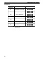
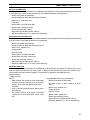
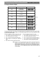
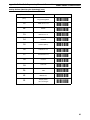
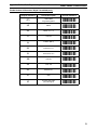
1. Global Default & Scanner Configurations
Computer Command
Function/Description
Bar Code Command
(Z7)
START/END
Programming Menu
U1
Return all parameters to
Default settings
1Y
Clear all prefixes
1Z
Clear all suffixes
P6
Disable Graph Mode
U0
Scanner Test Mode
U8
Read Rate Mode
U9
Graph Mode (TBD)
(Z7)
START/END
Programming Menu
Z1
Reset all values set by command
Z2
Save all values set by command
(not lost upon power off)
Z3
Display software settings
and version number
Z4
Display prefix/suffix value length
(expressed in hexa
decimal format)
-[8-V2-2Z-2[-Q7-V1-V9-V:-[8-[2-[3-[!-[5-
Note 1. * Use Z2 Command after computer command to store settings in memory
prior to power off. Where computer commands appear in parenthesis, bar
code commands must be used to program the scanner.
2. Default settings for “-C” types are indicated by a pointing hand symbol
(
) throughout the bar codes menus.
%
3. Default settings for “-P” types are indicated by a (•).
34
Appendix C - Bar Code Programming Menus & Commands
V500-LPN5627/V500-LPR5627
Scanner Test Mode (U0)
This mode resets all unit parameters to a predefined set of defaults for the purpose of putting the scanner into
a test mode which reads barcodes continuously. The predefined defaults are the following:
• Reads all barcodes by symbology
• No fixed number of digits defined (32 digits minimum).
• Normal scan, continuous scan.
• Large only.
• No verification, no "Bad Read (BR)".
• Buzzer 3KHz, volume maximum.
• Buzzer after decoding (10 ms).
• Good LED after decoding (green, 100 ms).
• RS-232C (9600 baud, 8, 1, no parity, no handshaking).
Straight Across Scan Mode (U3)
This mode resets all unit parameters to predefined defaults for the purpose of allowing straight across scanning
of up to 3 labels. The predefined defaults are the following:
• Reads all barcodes by symbology.
• No fixed number of digits defined (32 digits max.)
• Normal scan, multiple scan.
• Trigger disable.
• Small and large.
• No verification, no "Bad Read (BR)".
• Buzzer 3KHz and 2KHz, volume max.
• Buzzer after decoding (200 ms).
• Good LED after decoding (green, 200 ms).
• RS-232C (9600 baud, 8, 1, no parity, no handshaking).
Read Rate Mode (U8)
This mode resets all unit parameters to a predefined set of defaults for the purpose of checking the scanner
read rate. When activated, the test result is sent via RS-232C and indicates the ration of the number of successful read to the total number of attempts. The test result is reported in the following format:
500 d OK: 93.5%
*CODE-39 TEST*
Where:
• 500d indicates the number of times the decoder
ran while scanning at 500 scans per second (the
number can be lower the 500 with poor quality
barcodes).
• 93.5% indicates the percentage of good reads to
total attempts.
• The control character to be output is CD (0DE
carriage return line fed),”ESC[3A” (cursor 3 line
UP).
The predefined defaults are the following:
• Reads all barcodes by symbology.
• No fixed number of digits defined (32 digits
max.).
• Normal scan, multiple scan.
• Trigger disabled.
• Small and large.
• Buzzer 3 KHz, volume max.
• Buzzer after decoding (10 ms.)
• Good LED after decoding (green 100 ms)
• RS-232C (9600 bps, 8, 1, np, no handshaking).
35
Appendix C - Bar Code Programming Menus & Commands
V500-LPN5627/V500-LPR5627
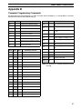
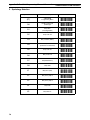
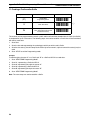
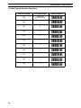
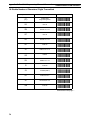
2. Symbology Selection
Computer Command
Function/Description
Bar Code Command
(Z7)
START/END
Programming Menu
A0
Enable all bar code
symbologies
A1
Only WPC
(including Addon)
A2
Only Code 39
A3
Only Codabar (NW-7)
A4
Only 2 of 5
(Industrial or Interleaved)
A5
Only Code 93
A6
Only Code 128
A7
Only MSI/Plessey
A8
Only IATA
J1
Only UPC (A/E)
J2
Only UPC (A/E)+2
J3
Only UPC (A/E)+5
J4
Only EAN
J5
Only EAN +2
-[8-B1-B2-B3-B!-B5-B6-B7-B8-B9-K2-K3-K!-K5-K6Continued on next page.....
36
Appendix C - Bar Code Programming Menus & Commands
V500-LPN5627/V500-LPR5627
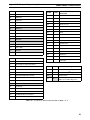
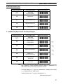
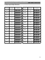
Symbology Selection (cont)
Computer Command
Function/Description
Bar Code Command
(Z7)
START/END
Programming Menu
J6
Only EAN +5
J7
Only Industrial 2 of 5
J8
Only Interleaved 2 of 5
Z9
Remote Menu
-[8-K7-K8-K9-[:-
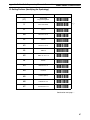
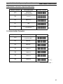
3. Add/Activate Specific Bar Code Symbologies
Computer Command
Function/Description
Bar Code Command
(Z7)
START/END
Programming Menu
B1
Enable all WPC
(including Addon)
-[8-C2-
B2
Enable Code 39
B3
Enable Codabar (NW-7)
B4
Enable 2 of 5
(Industrial/Interleaved)
-C5-
B5
Enable Code 93
(Factory Set)
B6
Enable Code 128
(Factory Set)
-C6-C7-
-C3-C!-
Note 1. * Use Z2 Command after computer command to store settings in memory
prior to power off. Where computer commands appear in parenthesis, bar
code commands must be used to program the scanner.
2. Default settings for “-C” types are indicated by a pointing hand symbol
(
) throughout the bar codes menus.
%
3. Default settings for “-P” types are indicated by a (•)
Continued on next page.....
37
Appendix C - Bar Code Programming Menus & Commands
V500-LPN5627/V500-LPR5627
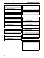
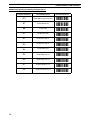
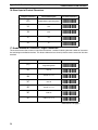
Add/Activate Specific Bar Code Symbologies (cont.)
38
Computer Command
Function/Description
(Z7)
START/END Programming Menu
B7
Enable MSI/Plessey
B8
Enable IATA
R1
Enable UPC (A/E)
R2
Enable UPC (A/E) +2
R3
Enable UPC (A/E) +5
R4
Enable EAN (13/8)
R5
Enable EAN (13/8) +2
R6
Enable EAN (13/8) +5
R7
Enable Industrial 2 of 5
R8
Enable Interleaved 2 of 5
Bar Code Command
-[8-C8-C9-S2-S3-S!-S5-S6-S7-S8-S9-
Appendix C - Bar Code Programming Menus & Commands
V500-LPN5627/V500-LPR5627
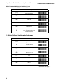
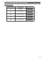
4. Delete/Deactivate Specific Bar Code Symbologies
Computer Command
Function/Description
Bar Code Command
(Z7)
START/END
Programming Menu
4A
Disable all WPC
(including Addon)
4B
Disable UPC (A/E)
4C
Disable UPC (A/E) +2
4D
Disable UPC (A/E) +5
4E
Disable EAN (13/8)
4F
Disable EAN (13/8) +2
4G
Disable EAN (13/8) +5
4H
Disable Code 39
4I
Disable Codabar (NW-7)
4J
Disable 2 of 5 (Industrial/
Interleaved)
4K
Disable Industrial 2 of 5
4L
Disable Interleaved 2 of 5
4M
Disable Code 93
-[8-5B-5C-5D-5E-5F-5G-5H-5I-5J-5K-5L-5M-5NContinued on next page.....
39
Appendix C - Bar Code Programming Menus & Commands
V500-LPN5627/V500-LPR5627
Delete/Deactivate Specific Bar (cont.)
Computer Command
Function/Description
Bar Code Command
(Z7)
START/END
Programming Menu
4N
Disable Code 128
4O
Disable MSI/Plessey
4P
Disable IATA
4Z
Disable all symbologies
-[8-5O-5P-5Q-5[-
5. Options for UPC
40
Computer Command
Function/Description
Bar Code Command
(Z7)
START/END
Programming Menu
-[8-
E2
UPC-A (13 Digits)
Add leading zero;
Enable check digit
E3
UPC-A (12 Digits)
Do not add leading zero;
Enable check digit
-F!-
E4
UPC-A (12 Digits)
Add leading zero;
Disable check digit
-F5-
E5
UPC-A (11 Digits)
Do not add leading zero;
Disable check digit
-F6-
E6
UPC-E (8 Digits)
Add leading zero;
Enable check digit
-F7-
E7
UPC-E (7 Digits)
Do not add leading zero;
Enable check digit
-F8-
E8
UPC-E (7 Digits)
Add leading zero;
Disable check digit
E9
UPC-A (6 Digits)
Do not add leading zero;
Disable check digit
-F3- %
-F9- %
-F:-
Appendix C - Bar Code Programming Menus & Commands
V500-LPN5627/V500-LPR5627
6. Options for Code 39
Computer Command
Function/Description
(Z7)
START/END
Programming Menu
7C
Enable 1 character (3 characters
including start/stop characters)
7D
Disable 1 character
C0
Disable check digit calculation
C1
Enable check digit calculation
C2
Transmit check digit
C3
Do not transmit check digit
D0
Do not transmit start/stop
characters (*……*)
D1
Transmit start/stop characters
(*……*)
Bar Code Command
-[8-8D-8E- %
-D1- %
-D2-D3- %
-D!-E1-E2- %
• 43 Data digits are available: 0 to 9, A to Z (caps only) plus.- $/ + % and space.
If a check digit is present, it will appear as part of the data.
• If the scanner is programmed to calculate the check digit, and the bar code is not printed with a check digit,
the bar code will not read.
• Another option available for Code 39 is to enable the reading of a single character bar code. See the section on Fixing the Digit for this option.
41
Appendix C - Bar Code Programming Menus & Commands
V500-LPN5627/V500-LPR5627
7. Options for Codabar (NW-7)
Computer Command
Function/Description
Bar Code Command
(Z7)
START/END
Programming Menu
7K
Enable 1 character (3 characters
including start/stop characters)
7L
Disable 1 character
F0
Do not transmit
start/stop characters
F1
Transmit start/stop
characters as ABCD/TN*E
F2
Transmit start/stop
characters as abcd/tn*e
F3
Transmit start/stop
characters as ABCD/ABCD
F4
Transmit start/stop
characters as abcd/abcd
F5
Transmit check digit
F6
Do not transmit check digit
F7
Do not calculate check digit
F8
Calculate check digit
(Modulo 10)
F9
Calculate check digit
(Modulo 16)
(AIM specifications)
-G:-
FB
Calculate check digit
(Modulo 7)
-GC-
-[8-8L-8M- %
-G1-G2-G3-G!-G5- %
-G6- %
-G7-G8- %
-G9-
Continued on next page.....
42
Appendix C - Bar Code Programming Menus & Commands
V500-LPN5627/V500-LPR5627
Codabar (NW-7 Format)
Start
Character
A....
a....
A....
a....
1 to 42
data digits
Check
digit
Stop
Character
....T
....t
....A
....a
• Codabar (NW-7) has four different start/stop character schemes as shown above. The check digit is
optional and, if present, would be the last character.
• If the scanner is programmed to calculate the check digit and the bar code is not printed with a check digit,
the bar code will not be read.
8. Options for Interleaved 2 of 5
Computer Command
Function/Description
(Z7)
START/END
Programming Menu
G0
Do not calculate check digit
G1
Calculate check digit
G2
Transmit Check digit
G3
Do not transmit check digit
7M
Enable 2 characters
7N
Disable 2 characters
Bar Code Command
-[8-H1- %
-H2-H3- %
-H!-8N-8O- %
2 of 5 Format (Standard and Interleaved)
1 to 44 data digits
numeric only (0 to 9)
CD
Check digit
Omron strongly recommends that the “Fixing the Number of Digits” featured on page 45 be employed
whenever 2 of 5 bar codes are used.
43
Appendix C - Bar Code Programming Menus & Commands
V500-LPN5627/V500-LPR5627
9. Options for IATA
Computer Command
Function/Description
Bar Code Command
(Z7)
START/END
Programming Menu
D2
Do not calculate check digit
D3
Calculate check digit
(CPN + Form + Serial)
D4
Calculate check digit
(Form + Serial)
D5
Calculate check digit
(All data)
D6
Transmit check digit
D7
Do not transmit check digit
-[8-E3- %
-E!-E5-E6-E7-E8- %
The IATA code is a variable length symbology with an optional check digit and non-printable start/stop
characters. The following characters are supported: Digits 0 up to 9.
The checksum is calculated as the modulo seven of the data string. IATA is an acronym for International
Air Transport Association.
String format
Meaning of Acronym
Number of digits (15 total)
CPN
AC
FC
SN
CD
Coupon
Airline
Code
Form
Code
Serial
Number
Check
Digit
1
3
2
8
1
• Enable check digit check.
• Selection of the check digit calculation.
• Disable transmission of the check digit.
Check digit calculation: If the check digit calculation is required, then the appropriate calculation method must
be selected.
44
Appendix C - Bar Code Programming Menus & Commands
V500-LPN5627/V500-LPR5627
10. Fixing the Number of Digits
Computer Command
Function/Description
Bar Code Command
(Z7)
START/END
Programming Menu
-[8-
7V
Enable fixation
(1 Length)
7W
Enable fixation
(2 Lengths)
(H0)
Disable fixation
(H1)
Enable fixation
(1 length)
(H4)
Enable fixation
(t lengths)
H2
Disable 1 character
Code 39 and Codabar (NW-7);
Disable 2 characters 2 of 5
-I3-
H3
Enable 1 character
Code 39 and Codabar (NW-7);
Enable 2 characters 2 of 5
-I!-
-I1-I2-I5%
To avoid truncation errors, the scanner can be programmed to only decode bar codes of one specific length,
i.e., containing a specific number of digits. It is also possible to program the scanner to only decode bar codes
of either of two specific lengths.
To fix one (1) length (or number of digits) of bar code:
To fix two (2) different lengths of bar codes:
1. Scan “START” to enter the programming mode.
1. Scan “START” to enter the programming mode.
2. Scan “Enable fixation (H1)” bar code.
2. Scan “Enable fixation (H4)” bar code.
3. Scan a sample bar code of the desired length.
3. Scan a sample bar code of the desired length #1.
4. Repeat Step #3, re-scanning the sample bar
code.
4. Scan a sample bar code of the desired length #2.
5. Scan “STOP” to exit the programming mode.
5. Scan “STOP” to exit the programming mode.
Note Fixation can also be programmed using computer commands through your
RS232 by typing <ESC>7V<CR> followed by <+>2 digit length 1<CR>. 7W
would be appropriate for length 2. Type <+>00<CR> to define either length as
no fixed number. “Fixing the Number of digits” can only be applied to Code 39,
Codabar (NW-7), 2 or 5 and MSI/Plessey. WPC, Code 39, IATA and Code 128
are not affected.
45
Appendix C - Bar Code Programming Menus & Commands
V500-LPN5627/V500-LPR5627
11. Creating a Prefix and/or Suffix
Computer Command
Function/Description
(Z7)
START/END
Programming Menu
1Y
Clear all Prefixes
Z4
Display Prefix/Suffix
value and length (expressed in
hexidecimal format)
Bar Code Command
-[8-2Z- %
-[5-
The scanner can be programmed to transmit a prefix and/or suffix with the decoded data. A Prefix (or a Suffix)
is composed of up to 4 characters. The following steps are used to establish a Prefix that will be transmitted
with the bar code data:
1. Scan Start.
2. Scan the bar code representing the symbology to which you wish to add a Prefix.
3. Scan the character(s) that will comprise the Prefix. Up to four numeric, alpha or control character(s) may be
used.
4. Scan “STOP” to exit the Programming mode.
Example:
To add the alpha character “A” as a Prefix and “B” as a Suffix to UPC-A bar code data:
1. Scan “START/END Programming Mode.”
2. Scan N1, representing a Prefix for UPC-A.
3. Scan 0A, representing the alpha character “A.”
4. Scan N6, representing a Suffix for UPC-A.
5. Scan 0B, representing the alpha character “B.”
6. Scan “START/END Programming Mode.”
Note The same steps are used to establish a Suffix.
46
Appendix C - Bar Code Programming Menus & Commands
V500-LPN5627/V500-LPR5627
12. Setting Prefixes (Identifying the Symbology)
Computer Command
Function/Description
(Z7)
START/END
Programming Menu
1Y
Clear all Prefixes
N1
UPC-A
M0
UPC-A +2 or +5
N2
UPC-E
M1
UPC-E +2 or +5
N3
EAN-13
M2
EAN –13 +2 or +5
N4
EAN-8
M3
EAN-8 +2 or +5
M4
Code 39
M5
Codabar (NW-7)
M6
Industrial 2 of 5
M7
Interleaved 2 of 5
Bar Code Command
-[8-2Z- %
-O2-N1-O3-N2-O!-N3-O5-N!-N5-N6-N7-N8Continued on next page.....
47
Appendix C - Bar Code Programming Menus & Commands
V500-LPN5627/V500-LPR5627
Setting Prefixes (Identifying the Symbology) (cont.)
Computer Command
Function/Description
Bar Code Command
(Z7)
START/END
Programming Menu
M8
Code 93
M9
Code 128
D8
IATA
N0
MSI/Plessey
-[8-N9-N:-E9-O1-
Z4
Display Prefix/Suffix
value and length (expressed in
hexidecimal format)
-[5-
13. Setting Suffixes (Identifying the Symbology)
Computer Command
Function/Description
Bar Code Command
(Z7)
START/END
Programming Menu
1Z
Clear all Suffixes
N6
UPC-A
O0
UPC-A +2 or +5
N7
UPC-E
O1
UPC-E +2 or +5
N8
EAN-13
-[8-2[-O7-P1-O8-P2-O9Continued on next page.....
48
Appendix C - Bar Code Programming Menus & Commands
V500-LPN5627/V500-LPR5627
Setting Suffixes (Identifying the Symbology) (cont.)
Computer Command
Function/Description
Bar Code Command
(Z7)
START/END
Programming Menu
O2
EAN–13 +2 or +5
N9
EAN-8
O3
EAN-8 +2 or +5
O4
Code 39
O5
Codabar (NW-7)
O6
Industrial 2 of 5
O7
Interleaved 2 of 5
O8
Code 93
O9
Code 128
D9
IATA
N5
MSI/Plessey
Z4
Display Suffix
value and length
-[8-P3-O:-P!-P5-P6-P7-P8-P9-P:-E:-O6-[5-
Note The global default, also clears all suffixes.
49
Appendix C - Bar Code Programming Menus & Commands
V500-LPN5627/V500-LPR5627
14. Direct Input of Numeric Characters
50
Computer Command
Function/Description
Bar Code Command
(Z7)
START/END
Programming Menu
Q0
0
Q1
1
Q2
2
Q3
3
Q4
4
Q5
5
Q6
6
Q7
7
Q8
8
Q9
9
-[8-R1-R2-R3-R!-R5-R6-R7-R8-R9-R:-
Appendix C - Bar Code Programming Menus & Commands
V500-LPN5627/V500-LPR5627
15. Direct Input of Alpha Characters
Computer
Command
Function/
Description
Bar Code
Command
Computer
Command
Function/
Description
(Z7)
START/END
Program Menu
0N
N
0A
A
0O
O
0B
B
0P
P
0C
C
0Q
Q
0D
D
0R
R
0E
E
0S
S
0F
F
0T
T
0G
G
0U
U
0H
H
0V
V
0I
I
0W
W
0J
J
0X
X
0K
K
0Y
Y
0L
L
0Z
Z
0M
M
-[8-1B-1C-1D-1E-1F-1G-1H-1I-1J-1K-1L-1M-1N-
(Z7)
START/END
Program Menu
Bar Code
Command
-1O-1P-1Q-1R-1S-1T-1U-1V-1W-1X-1Y-1Z-1[-[8-
51
Appendix C - Bar Code Programming Menus & Commands
V500-LPN5627/V500-LPR5627
16. Direct Input of Control Characters
Computer Command
Function/Description
(Z7)
START/END Programming Menu
1A
STX
1B
ETX
1C
CR
1D
LF
Bar Code Command
-[8-2B-2C-2D-2E-
17. Enable Number of Characters / Digits Transmitted
This feature instructs the scanner to calculate and transmit a number indicating the total number of characters
that are being transmitted to the host. This feature allows the host to verify that the correct amount of data was
received.
Computer Command
Function/Description
Bar Code Command
(Z7)
START/END
Programming Menu
3A
UPC-A
3B
UPC-A +2 or +5
3C
UPC-E
3D
UPC-E +2 or +5
3E
EAN-13
3F
EAN-13 +2 or +5
-[8-!B-!C-!D-!E-!F-!GContinued on next page.....
52
Appendix C - Bar Code Programming Menus & Commands
V500-LPN5627/V500-LPR5627
Enable Number of Characters / Digits Transmitted (cont.)
Computer Command
Function/Description
Bar Code Command
(Z7)
START/END
Programming Menu
3G
EAN-8
3H
EAN-8 +2 or +5
3I
Code 39
3J
Codabar (NW-7)
3K
Industrial 2 of 5
3L
Interleaved 2 of 5
3M
Code 93
3N
Code 128
3O
MSI/Plessey
3P
IATA
3Z
Transmit data length
(all symbologies)
-[8-!H-!I-!J-!K-!L-!M-!N-!O-!P-!Q-