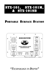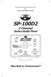
1
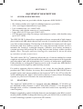
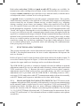
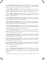
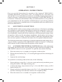
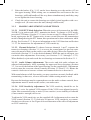
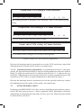
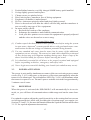
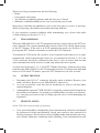
Aquacom®
SSB-2001B-2
2-Channel, Single-Sideband
Acoustic Transceiver
“Technology in Depth”
- NOTICE This manual and the information contained herein are provided for use as a maintenance and operation guide. No license or rights to manufacture, produce, and/
or sell either the manual or articles described herein are given. Undersea Systems
International, Inc., dba Ocean Technology Systems, reserves the right to change
specifications without notice. We recommend that all users read and fully understand
this manual before using the Aquacom® SSB-2001B-2.
All statements, technical information, and recommendations herein are based on
tests we believe to be reliable, but the accuracy or completeness thereof is not guaranteed; and the following is made in lieu of all warranties, expressed or implied,
including the implied warranties of merchantability and fitness for purpose: Seller’s
and Manufacturer’s only obligation shall be to replace such quantity of the product
proved to be defective. Before using, the user shall determine the suitability of the
product for intended use, and the user assumes all risk and liability whatsoever in
connection therewith. Neither Seller nor Manufacturer shall be liable either in tort
or in contract for any loss or damage—direct, incidental, or consequential—arising
from the use of or the inability to use the product. No statement or recommendation not contained herein shall have any force or effect unless it is in an agreement
signed by officers of the Seller and Manufacturer.
- IMPORTANT SAFETY NOTICE (Please read before using product.)
It is absolutely essential that all divers are properly trained and equipped and
fully understand this user’s manual before attempting to use the Aquacom®
SSB-2001B-2.
While the SSB-2001B-2 provides divers with good underwater communications, it does not change or eliminate the potential hazards of diving!
Refer to the Library page of our Web site, www.otscomm.com, for a list of
any changes made to this manual since its publication.
Copyright © 2008 by Undersea Systems International, Inc., dba
Ocean Technology Systems. All rights reserved.
Specifications subject to change without prior notice.
i
506087-000 (C)
TABLE OF CONTENTS
Section 1: Introduction ................................................................................1
1.1 General..........................................................................................1
1.2 Specifications................................................................................2
1.3 When You Receive Your Shipment...............................................3
Section 2: Equipment Description . ............................................................4
2.1 General Description......................................................................4
2.2 Features.........................................................................................4
2.3 Functions and Controls.................................................................5
2.3.1 Manual Push-to-Talk (PTT) Switch...................................5
2.3.2 Voice-Operated Transmitter (VOX)...................................7
2.3.3 Channels/Frequencies........................................................7
2.3.4 Receive Volume..................................................................7
2.3.5 Side Audio Volume.............................................................7
2.3.6 Squelch...............................................................................7
2.4 Components and Accessories........................................................7
2.4.1 Transducer..........................................................................7
2.4.2 Earphone-Microphone (EM) Assemblies...........................8
2.4.2.1 EMA-2 (911060-001).......................................... 8
2.4.2.2 EMA-2SM (911060-098)....................................8
2.4.2.3 EMX-2 (911060-008)..........................................8
2.4.2.4 EMX-2B (911060-026)........................................8
2.4.2.5 EMO-2 (900096-686)..........................................8
2.4.2.6 EMH2-1 (911060-009)........................................8
2.4.2.7 EMH2-1SM (911060-100)..................................8
2.4.2.8 EMS-2 (911060-017)...........................................8
2.4.2.9 LAR V Adapter (900282-000).............................9
2.4.2.10EMD-2 (911060-067)..........................................9
2.4.2.11 EMD-2SM (911060-101)....................................9
2.4.2.12EMDG-2 (911060-076).......................................9
2.4.2.13EMH1-1 (900332-000)...................................... 10
2.4.2.14EMH1-1SM (900332-001)................................ 10
2.4.2.15EMMT-1 (911060-090).....................................10
2.4.2.16EMMT-1SM (911060-102)................................ 10
2.4.2.17EMMT-2 (911060-091).....................................10
2.4.2.18EMMT-2SM (911060-103)................................10
2.4.2.19 EM-OTS-2 (910369-000)..................................10
2.4.2.20 EM-OTS-2SM (910379-000).............................10
2.4.3 Microphones..................................................................... 10
2.4.3.1 ME-16R Hot-Mic® (912086-000)......................10
2.4.3.2 Super Mic® Depth Master.................................. 11
2.5 Compatible Surface/Diver Transceivers..................................... 11
Section 3: Operation Instructions ............................................................12
3.1 Adjustments and Settings............................................................12
ii
3.1.1 Accessing the Internal Controls.......................................12
3.1.2 Making Adjustments and Settings....................................13
3.1.2.1 VOX/PTT Mode Selection................................13
3.1.2.2 Channel Selection..............................................13
3.1.2.3 Audio Volume Adjustments...............................13
3.1.2.4 VOX Sensitivity Adjustment.............................13
3.1.2.5 Squelch Sensitivity Adjustment.........................14
3.2 Setup Before a Dive....................................................................14
3.3 Power Activation.........................................................................17
3.4 Reception....................................................................................17
3.5 Transmission...............................................................................18
3.6 After the Dive.............................................................................18
3.7 Helpful Hints...............................................................................18
3.8 Examples of Underwater Communication..................................19
3.8.1 Calls Between Surface, Subs, or Divers..........................19
3.8.2 Calls Between Divers and Surface, Subs, or Bells..........19
Section 4: Batteries and Charging . ..........................................................20
4.1 Battery Installation or Replacement............................................21
4.2 Battery Charging.........................................................................21
4.2.1 Charging Through the Transceiver...................................21
4.2.2 Charging the Battery Directly..........................................22
Section 5: Maintenance .............................................................................23
5.1 General Maintenance..................................................................23
5.2 Periodic Maintenance..................................................................23
Section 6: The Basics of Sound in Water .................................................24
6.1 Background.................................................................................24
6.2 Factors That Affect Sound in Water............................................24
6.2.1 Distance............................................................................24
6.2.2 Water Density...................................................................24
6.2.3 Water Temperature...........................................................24
6.2.4 Background Noise............................................................26
6.2.5 Zones of Silence...............................................................26
Limited Warranty ......................................................................................28
Tables
Table 1: Compatible Earphone-Microphone Assemblies........................9
Table 2: Battery Chargers Available for the SSB-2001B-2...................20
Illustrations
Figure 1. SSB-2001B-2 with typical earphone-microphone assembly...1
Figure 2. Components of the SSB-2001B-2............................................6
Figure 3. Adjustment controls..................................................................6
Figure 4. Effect of VOX sensitivity adjustment....................................14
Figure 5. Effect of squelch sensitivity adjustment.................................15
Figure 6. Thermoclines affect the ultrasonic signal...............................25
Figure 7. Water current dead zone.........................................................26
Figure 8. Communication through indirect and direct paths.................27
iii
SECTION 1
INTRODUCTION
1.1
GENERAL
Congratulations! You have just purchased one of the finest, state-of-the-art underwater communication systems available. The Aquacom® SSB-2001B-2 is an
ultrasonic, single-sideband transceiver designed to allow through-water voice
communications among divers and the surface. It employs digital signal processing
(DSP) techniques that ensure the highest-quality intelligibility possible. Standard
features include automatic electronic switching between voice activation (VOX)
and push-to-talk (PTT) modes, allowing the diver total function control underwater;
separate volume controls for receive and side audio levels; two channels; a heavyduty housing; covertibility to a portable surface station; and more! In all, you will
find that the functionality and versatility of the SSB-2001B-2 will greatly enhance
your diving experience.
This user’s manual contains information regarding the Aquacom® SSB-2001B-2
underwater communication system, including earphone-microphone assemblies
and support equipment.
The SSB-2001B-2 with optional EMA-2 earphone-microphone assembly is illustrated in Figure 1.
Figure 1. SSB-2001B-2 with typical earphone-microphone assembly
1
1.2
SPECIFICATIONS
Calm sea: Greater than 1000 meters nominal
Sea State 6: 200 meters nominal
Acoustic output power:
5 watts PEP1 (178.5 dB re 1 uPA at 1 meter)
Audio frequency response: 300–4000 Hz
Receiver sensitivity:
–110 dBv
Automatic gain control:
120 dB dynamic range
Transmitter activation:
Voice-operated transmitter (VOX) or manual activation (PTT)
2
32.768 kHz USB (Channel 1)
Standard frequencies :
25 kHz USB (Channel 7)3
Battery life:
Eight AA alkaline batteries: 12 hours, assuming
10% transmission cycle.
RB-11 nickel-metal hydride battery pack (optional): 6 hours.
Battery type:
Eight AA alkaline cells or optional RB-11 nickelmetal hydride rechargeable battery pack
Transducer:
Piezoelectric type
Earphone:
Ceramic type
Housing:
Injection-molded, high-impact, glass-filled ABS
plastic
Maximum depth:
400 ft.
Housing dimensions:
Height 7.60”, width 3.55”, depth 1.80”
Operating temperature:
0°C to +60°C (+32°F to +140°F)
Storage temperature:
–10°C to +60°C (–14°F to +140°F)
Low-battery indication:
Red flashing LED on housing and beep in earphone
Connector type:
Hi-Use®
Battery chargers:
RCS-15 and RCS-16: 90–264 VAC, 50–60 Hz
input; 14.7 VDC output; charging current 800 mA
RCL-7A: 90–264 VAC, 50–60 Hz input; 24 VDC
(diver units) and 16 VDC (surface units) output
Nominal range:
1.PEP = “peak envelope power.”
2.These standard frequencies are also used by the STX-101M and the SSB-1001B.
3.32.768 kHz USB is the more efficient channel with the supplied TA-5 transducer, but 25
kHz USB is more efficient if the optional TA-4 transducer is used (see Section 2.4.1).
2
1.3
When you receive your shipment
Upon arrival of your equipment, inspect the shipping container for dents, gouges,
or any other evidence of rough handling.
When you remove your Aquacom® SSB-2001B-2 transceiver from the shipping
container and the protective case, visually inspect it for damage or other problems.
If any damage is evident, immediately file a claim with the carrier. Forward a copy
of the damage claim to Ocean Technology Systems, Santa Ana, CA. We will then
make arrangements for repair or replacement.
Also inspect the contents of the protective case to verify that all items have been
included. See Section 2.1 for a list of items supplied with the SSB-2001B-2.
Note: Although the Aquacom® SSB-2001B-2 is rugged in design, exercise care to
ensure that problems are not caused by improper handling. Store the unit in a safe,
secure area after unpacking it.
3
SECTION 2
EQUIPMENT DESCRIPTION
2.1
General Description
The following items are provided with the Aquacom® SSB-2001B-2:
• SP-8 battery holder (for eight AA alkaline batteries) (p/n H024)
• AD-1 steel-tipped adjustment tool (p/n P088)
• User’s manual (doc. no. 506087-000)
• Warranty card with the transceiver’s serial number
• Large label of OTS logo (p/n 504013-002)
• OTS designed gear bag (for storage and transport), nylon, with shoulder strap
(p/n 134153-000)
The SSB-2001B-2 is housed in a watertight enclosure constructed of high-impact,
glass-reinforced ABS plastic that will not corrode if scratched and is designed for
easy belt or tank mounting. The housing is divided into two major parts: the upper
electronics and lower battery sections. An o-ring between the sections serves to
maintain the housing’s watertight integrity. Stainless steel latches maintain a
constant pressure that preloads the o-ring and prevents leakage within specified
depths. (Note: The upper and lower housings are a matched set; do not mix them
up with those of other transceivers.)
The cable with a Hi-Use® connector allows the use of various standard or custom
earphone-microphone (EM) assemblies designed for an assortment of diving masks
and rebreathers and with microphones for a variety of underwater applications.
Either alkaline or rechargeable batteries can be used. Overall, the SSB-2001B-2
was designed with simplicity and flexibility in mind.
For surface operation (diver-to-surface or vice versa), the user has the option to
purchase the CDK-6 Surface Accessory Kit to transform the SSB-2001B-2 into a
portable surface unit. Also available are the Aquacom® STX-101, STX-101M, SP100D, and Magnacom® MAG-1001S surface stations. (Contact Ocean Technology
Systems or your local OTS dealer for more information.)
2.2
FEATURES
The Aquacom® SSB-2001B-2 is equipped with two channels, 32.768 kHz upper sideband (USB) (Channel 1) and 25 kHz USB (Channel 7). It is designed for
through-water, wireless communication with other transceivers operating at the
same frequency.
Power is supplied by eight AA alkaline batteries (not included) or the RB-11 nickelmetal hydride (NiMH) rechargeable battery pack (p/n 900284-000, available from
Ocean Technology Systems or your local OTS dealer).
4
Both voice activation (VOX) and push-to-talk (PTT) modes are available for
transmission, and switching between them is done electronically for convenience.
Separate volume controls are provided for receive and side audio, so that the diver
can adjust the relative volume levels to his preference.
A squelch feature is included to provide quieter communications. The squelch,
which functions similarly to the squelch of a CB radio, helps suppress background
noises created by sea creatures, human activity, or other sources (e.g., snapping
shrimp, croakers, motor boats, pool pumps). Below the squelch level set by the
user, the squelch feature prevents any sound (presumably just noise) from being
heard through the earphones. Louder sound (e.g., received communications) will
“break” the squelch, allowing the received sounds to be heard. When the squelch
is used, you will hear only the communication signals strong enough to break the
squelch, so communication range is limited. If long communication range is desired,
minimal or no squelch should be used. If the diver is working close-range to other
divers or a surface station, an increased setting can be used. The optimal squelch
sensitivity setting for your diving conditions is one that is high enough to screen
out as much ambient noise as possible while still allowing all communications
from your group to be heard.
2.3
Functions and Controls
This section describes the various functions and controls of the Aquacom® SSB2001B-2. For detailed instructions for how to make adjustments and operate the
unit, see Section 3.
Refer to Figures 2 and 3 for the locations of the items referred to in this section. To
access the controls depicted in Figure 3, follow the instructions in Section 3.1.1 to
separate the upper and lower housings and to reseal them afterward.
The SSB-2001B-2 provides a switch for channel selection in addition to manual
adjustment controls for receiver and side audio listening volumes and squelch and
VOX sensitivities (Fig. 3). Because the unit is opened to access these controls,
adjustments must be made on the surface, not while diving. An AD-1 steel-tipped
adjustment tool is provided with the SSB-2001B-2. Switching between voiceactivation (VOX) and push-to-talk (PTT) transmission modes is done electronically
with PTT button push sequences and thus can be done while diving.
2.3.1 Manual Push-to-Talk (PTT) Switch: The PTT button on the
earphone-microphone (EM) assembly (sold separately) is used to enter transmission
mode manually and to toggle between voice activation (VOX) and manual PTT
transmission modes. Because there are many different configurations of diving
masks, the location of the PTT button varies among EM assemblies. See Sections
3.1.2.1 (VOX/PTT Mode Selection) and 3.5 (Transmission) for instructions for use
of the PTT and Section 2.4.2 for information about available earphone-microphone
assemblies.
5
Key
(1) Hi-Use® connector for EM
assembly
(2) Strike
(3) Belt clip
(4) O-ring to seal housing
(5) Latch
(6) Lower housing
(7) SP-8 battery holder
(8) Battery snap connector
(9) Upper housing
(10)Gripper ring
(11)O-ring to seal transducer
connection
(12)Transducer
(13)Activating water-contact
screws
(14)Power/charging indicator
LED
Figure 2. Components of the SSB-2001B-2
Key
(1) Channel selection switch
(2) Receive volume control
(3) Squelch sensitivity control
(4) VOX sensitivity control
(5) Side audio volume control
Figure 3. Adjustment controls
6
2.3.2Voice-Operated Transmitter (VOX): VOX operation provides hands-free communications. When the SSB-2001B-2 is in VOX transmission
mode, simply talk for the unit to transmit automatically. The diver can adjust the
VOX sensitivity with a control (Fig. 3, #4) to customize the VOX response to his
voice and the level of ambient noise. It is a two-turn control, meaning it will rotate
in either direction a total of two times before it stops. Section 3.1.2.1 provides
instructions for switching between VOX and PTT modes, and Section 3.1.2.4
describes how to adjust the VOX sensitivity.
2.3.3 Channels/Frequencies: The SSB-2001B-2 provides two channels for transmission and reception: 32.768 kHz USB (Channel 1) and 25 kHz USB
(Channel 7). 32.768 kHz USB is the more efficient channel with the supplied TA-5
transducer (Fig. 2, #12), but 25 kHz USB is more efficient if the optional TA-4
transducer is used instead. See Section 3.1.2.2 for channel selection instructions.
2.3.4 Receive Volume: A manual control (Fig. 3, #2) is used to adjust
the listening volume of communication signals received from other transmitters.
Rotation clockwise increases the volume and counterclockwise decreases it. It is
a two-turn control, rotating in either direction a total of two times before it stops.
2.3.5 Side Audio Volume: Side audio (also known as “sidetone”) is the
diver’s transmitted signal heard through his own earphones. Side audio is useful for
the diver to verify he is actually transmitting. Volume is changed by rotation of the
side audio volume control (Fig. 3, #5), clockwise to increase and counterclockwise
to decrease. It is a two-turn control, fully rotating twice before stopping.
2.3.6 Squelch: As explained in Section 2.2, the squelch helps to limit the
background noise heard by the diver. The proper setting depends on the specific
requirements of the dive. Squelch adjustment is accomplished via a manual control
(Fig. 3, #3) and is described in Section 3.1.2.5. It is a two-turn control, meaning it
will rotate in either direction a total of two times before it stops.
2.4
Components and Accessories
2.4.1 Transducer: The transducer provides the “antenna” for the transceiver to transmit and receive messages. It is mounted on the top of the upper
housing (Fig. 2, #12) and is removable via a connector. A large gripper ring (Fig.
2, #10) provides a means to remove and reinstall the transducer easily, by holding
the ring for stability while unscrewing the transducer.
Installed onto the standard Aquacom® SSB-2001B-2 is a TA-5 transducer, which
operates more efficiently and therefore provides greater output power at Channel 1
(32.768 khz USB) than at Channel 7 (25 kHz USB). If you require greater output
power with Channel 7 (25 kHz USB) than with Channel 1, obtain an SSB-2001B-2 with a TA-4 transducer, available as a special order from Ocean Technology
Systems or through your local OTS dealer.
7
An o-ring is located inside the transducer connector (Fig. 2, #11) to maintain a
watertight seal. When reinstalling the transducer after having removed it from the
upper housing, be sure to replace the o-ring to protect the connector pins from
water entry and subsequent corrosion.
2.4.2 Earphone-Microphone (EM) Assemblies: We offer our
standard microphones integrated into EM assemblies designed to fit the communication port of full-face masks (FFMs) produced by various manufacturers. Table
1 is a compatibility chart of some of the standard EM assemblies available for use
with Aquacom® diver transceivers. Note: If you have a diving helmet or FFM that
is not on the compatibility chart, contact Ocean Technology Systems or your local
OTS dealer for availability or for information on custom EM assemblies.
The following are full descriptions of each of the EM assemblies listed in Table
1:
2.4.2.1 EMA-2 (911060-001): The EMA-2 EM assembly is designed for all
Divator MKII (“AGA”) full-face masks (FFMs). It has two ceramic earphones with
holders, an ME-16R Hot-Mic®, a Hi-Use® connector, and a push-to-talk (PTT) button. The assembly is installed into the Divator MKII FFM communication port.
2.4.2.2 EMA-2SM (911060-098): The EMA-2SM EM assembly is designed
to be installed into all Divator MKII (“AGA”) FFMs. It consists of two ceramic
earphones with holders, a Super Mic, a Hi-Use® connector, and a PTT button. The
assembly is installed into the Divator MKII FFM communication port.
2.4.2.3 EMX-2 (911060-008): The EMX-2 EM assembly is designed for the
EXO-26 original FFM. It consists of two dynamic earphones, an ME-16R HotMic, a Hi-Use® connector, and a PTT button.
2.4.2.4 EMX-2B (911060-026): The EMX-2B EM assembly is designed for the
EXO-26 standard full-face mask. It is similar to the EMX-2 but fits the balancedregulator version of the EXO-26 with an oral-nasal cavity.
2.4.2.5 EMO-2 (900096-686): The EMO-2 EM assembly is designed to be installed into the Ocean Reef NIRA Neptune FFM. It has two earphones with holders,
a Hot-Mic, a Hi-Use® connector, and a PTT button. It is installed into a port on the
side of the FFM.
2.4.2.6 EMH2-1 (911060-009): The EMH2-1 EM assembly is optionally included
with the HM-2 mouth mask. It has one head strap, one ceramic earphone, a HotMic, a Hi-Use® connector, and a PTT button (located on the HM-2 mask).
2.4.2.7 EMH2-1SM (911060-100): The EMH2-1SM EM assembly is optionally
included with the HM-2 mouth mask. It has a head strap, one ceramic earphone, a
Super Mic, a Hi-Use® connector, and a PTT button (on the HM-2 mask).
2.4.2.8 EMS-2 (911060-017): The EMS-2 is an EM assembly designed to be
8
Table 1. Compatible Earphone-Microphone Assemblies
Part Number
Type
Microphone
Earphones
EMA-2
Model Number
911060-001
Standard ear-mic
Hot-Mic®
Dual
Mask/Rebreather
EMA-2SM
911060-098
Standard ear-mic
Super Mic®
Dual
Divator MK II FFM
EMA-SW-1
910274-000
SW ear-mic
Hot-Mic
Dual
Divator MK II FFM
EMA-SW-1SM
910274-001
SW ear-mic
Super Mic
Dual
Divator MK II FFM
EMA-MK24
910279-000
SW ear-mic
Hot-Mic
Dual
MK-24 FFM
EMA-MK24-SM
910279-001
SW ear-mic
Super Mic
Dual
MK-24 FFM
EMDG-2
911060-076
Standard ear-mic
ME-500
Dual
Dräger Panorama Nova
EMX-2
911060-008
Standard ear-mic
Hot-Mic
Dual
EXO-26 original
Divator MK II FFM
EMX-2B
911060-026
Standard ear-mic
Hot-Mic
Dual
EXO-26 standard
EMH-MAG2
900332-000
Standard ear-mic
Hot-Mic
Single
HM-1 mouth mask
HM-1 mouth mask
EMH-MAG2SM
900332-001
Standard ear-mic
Super Mic
Single
HM-1SW
910281-000
SW ear-mic
MIL-500B
Single
HM-1 mouth mask
HM-1SW-SM
910281-001
SW ear-mic
Super Mic
Single
HM-1 mouth mask
EMH-1
911060-009
Standard ear-mic
Hot-Mic
Single
HM-2 mouth mask
EMH-1SM
911060-100
Standard ear-mic
Super Mic
Single
HM-2 mouth mask
LAR V Adapter
900282-000
Standard ear-mic
ME-500
Single
LAR V rebreather
LAR5-SW
900282-006
SW ear-mic
Dynamic mic
Dua
LAR V rebreather
EMD-2
911060-067
Standard ear-mic
Hot-Mic
Dual
M-48 SuperMask®
EMD-2SM
911060-101
Standard ear-mic
Super Mic
Dual
M-48 SuperMask®
EM-KMS-48
910280-000
SW ear-mic
Hot-Mic
Dual
M-48 SuperMask®
EM-KMS-48SM
910280-002
SW ear-mic
Super Mic
Dual
M-48 SuperMask®
EMMT-1
911060-090
Standard ear-mic
Hot-Mic
Single
Mantis FFM
EMMT-1SM
911060-102
Standard ear-mic
Super Mic
Single
Mantis FFM
EMMT-2
911060-091
Standard ear-mic
Hot-Mic
Dual
Mantis FFM
EMMT-2SM
911060-103
Standard ear-mic
Super Mic
Dual
Mantis FFM
EMO-2
900096-686
Standard ear-mic
Hot-Mic
Dual
Ocean Reef FFM
EMS-2
911060-017
Standard ear-mic
Hot-Mic
Dual
ScubaPro FFM
EM-OTS-2
910369-000
Standard ear-mic
Hot Mic
Dual
Guardian FFM
EM-OTS-2SM
910379-000
Standard ear-mic
Super Mic
Dual
Guardian FFM
installed into a ScubaPro FFM. It consists of two earphones with holders, a HotMic, a PTT button, and a Hi-Use® connector.
2.4.2.9 LAR V Adapter (900282-000): This adapter is placed between the inhalation hose and LAR V bite-mouth/DSV t-bit assembly. It is designed to allow
basic words to be transmitted without the need for a full or half mask. It consists of
one earphone, an ME-500 microphone, a Hi-Use® connector, and a PTT button.
2.4.2.10 EMD-2 (911060-067): The EMD-2 EM assembly is designed to be
installed into the M-48 SuperMask® FFM. It consists of two earphones, earphone
holders, a Hot-Mic, a Hi-Use® connector, and a PTT button.
9
2.4.2.11 EMD-2SM (911060-101): The EMD-2SM EM assembly is designed to
be installed into the M-48 SuperMask® FFM. It consists of two earphone/earphone
holders, a Super Mic, a Hi-Use® connector, and a PTT button.
2.4.2.12 EMDG-2 (911060-076): This assembly is designed to be installed into
the Dräger Panorama Nova Dive Mask. It consists of two earphones, earphone
holders, an ME-500 microphone, a Hi-Use® connector, and a PTT button.
2.4.2.13 EMH1-1 (900332-000): This assembly is designed to be installed into
the HM-1 silicone half mask. It consists of one earphone, a Hot-Mic, a Hi-Use®
connector, and a PTT button.
2.4.2.14 EMH1-1SM (900332-001): The EMH1-1SM EM assembly is designed
to be installed into the HM-1 silicone half mask. It consists of one earphone, a
Super Mic, a Hi-Use® connector, and a PTT button.
2.4.2.15 EMMT-1 (911060-090): The EMMT-1 EM assembly is designed to be
installed into the Mantis FFM. It consists of one earphone, an earphone holder, a
Hot-Mic, a Hi-Use® connector, and a PTT button.
2.4.2.16 EMMT-1SM (911060-102): The EMMT-1SM EM assembly is designed
to be installed into the Mantis FFM. It consists of one earphone/earphone holder,
a Super Mic, a Hi-Use® connector, and a PTT button.
2.4.2.17 EMMT-2 (911060-091): This assembly is designed to be installed into
the Mantis FFM. It consists of two earphones, two earphone holders, a Hot-Mic,
a Hi-Use® connector, and a PTT button.
2.4.2.18 EMMT-2SM (911060-103): This assembly is designed to be installed
into the Mantis FFM. It consists of two earphone/earphone holders, a Super Mic,
a Hi-Use® connector, and a PTT button.
2.4.2.19 EM-OTS-2 (910369-000): This assembly is designed to be installed
into the Guardian FFM. It consists of two earphone/earphone holders, a Hot-Mic,
a Hi-Use® connector, and a PTT button.
2.4.2.20 EM-OTS-2SM (910379-000): This assembly is designed to be installed
into the Guardian FFM. It consists of two earphone/earphone holders, a Super Mic,
a Hi-Use® connector, and a PTT button.
2.4.3
Microphones:
2.4.3.1 ME-16R Hot-Mic® (912086-000): The ME-16R Hot-Mic® is a 150-ohm,
water-resistant microphone element. It is a state-of-the art dynamic microphone
element designed to give you long, trouble-free use and the highest intelligibility
possible.
Although the Hot-Mic is trouble free, it should be maintained. Rinse it with
10
freshwater after use to get all dirt, debris, or salt water from the grill. Dry it with a
clean, soft towel. If the element ever needs to be replaced, it is easily removed by
unscrewing the two small screws located on its base.
Getting the microphone wet does not harm it. However, the microphone element
can only withstand an 8- to 10-foot depth/pressure differential. If you removed your
diving FFM at the back of the boat and the microphone became wet, there would
be no problem; but if the FFM with element dropped more than 8 to 10 feet into the
water, the change in pressure probably would damage the microphone element. In
tests we have taken off the FFM at 30 feet and replaced it, still at 30 feet, without
any problem; but if one were to take off the FFM at 30 feet and drop down to 40
feet, the pressure difference may damage the microphone.
2.4.3.2 Super Mic® Depth Master: The Super Mic offers patented technology*
that overcomes a limitation of other microphones. It can be used at any depth and—
unlike the Hot-Mic or many other microphones—can withstand changes in depth
while submerged, so it will not be damaged if the diver needs to descend with the
mask flooded (e.g., on removal and stowage of the full-face mask when switching
to another air system). It is a ceramic microphone with a compact, lightweight
design and noise-cancelling properties, reducing background noises for clearer
communications. When only the highest quality of intelligibility is required, the
Hot-Mic is the preferred choice; but the Super Mic’s intelligibility is sufficient for
most diving situations.
To assure clear communications when using the Super Mic, it should be no more
than 1/4 inch from the corner of the diver’s mouth.
After each dive, clean the Super Mic by rinsing it with freshwater and drying it
with a clean, soft towel. No other maintenance is required.
Note: Do not press on the microphone diaphragm; doing so may cause damage.
2.5
Compatible Surface/Diver Transceivers
The SSB-2001B-2 transmits to and receives from any transceiver that is within
range and set to the same frequency. The following are compatible transceivers
manufactured by OTS:
Diver units:
SSB-2010, SSB-1001B, Buddy Phone (e.g., XT-100, OTS-BUD,
MKII-BUD, MTS-BUD, SCU-BUD, DSI-BUD, RX-100),
MAG-1003D, MAG-1004HS
Surface units:
STX-101, STX-101M, STX-101SB (25-kHz version), SP-100,
SP-100D, MAG-1001S (a version with at least one compatible
frequency must be requested), MAG-1003-PS
Diving bell unit: BELL-200
*U.S. Patent no. 7,170,822; EU patent nos. 000458351-0001, -0002, -0003, -0004, -0005, -0006.
11
Section 3
Operation Instructions
Here are provided instructions for operation of the Aquacom® SSB-2001B-2,
including adjustments, setup before a dive, use during the dive, and what to do
after the dive is over. Information on batteries, including charging instructions, is
found in Section 4. Instructions for proper maintenance of the SSB-2001B-2 are
in Section 5. With more information to help you understand how to set up and use
your equipment for the best possible communications in your diving situation,
Section 6 explains how communication is accomplished underwater and discusses
the factors that affect it.
3.1
Adjustments and Settings
The SSB-2001B-2 offers various settings to make best use of its features, including
the capability to make manual adjustments to define the sensitivities of the VOX
and squelch systems. Because no standards for design of full-face masks have
been established, virtually all full-face masks have different internal designs. Some
designs have little room for microphone installation, which makes it necessary to
have a more sensitive setting. Overall, the ability to make these adjustments offers
the user more options to customize the transceiver for optimal communications.
The following instructions explain how to make the adjustments and settings necessary for effective operation of the SSB-2001B-2. Refer to Section 2.3 (Functions
and Controls) for the locations and descriptions of the controls.
3.1.1 Accessing the Internal Controls: Most of the adjustments
and settings described in this section require the upper and lower housings of the
SSB-2001B-2 transceiver to be separated. To open the unit, do the following:
1. Place the transceiver so it stands on or against a stable surface.
2. Release the two latches (Fig. 2, #5) securing the upper and lower housings (#6
and #9).
3. Separate the two housings.
To rejoin the two housings and seal the unit, do the following:
1. Ensure the large o-ring (Fig. 2, #4) rests evenly and securely inside the groove
along the bottom of the upper housing (#9).
2. Connect the battery snap connector (Fig. 2, #8) to the RB-11 battery or SP-8
battery holder (#7).
3. Being careful not to pinch the battery wire (Fig. 2, #8), join together the upper
and lower housings such that their surfaces are completely flush.
4. Place the transceiver so it stands on or against a stable surface.
12
5. Raise the latches (Fig. 2, #5) on the lower housing over the catches (#2) on
the upper housing. While taking care to maintain the seal between the two
housings, pull both handles all the way down simultaneously until they snap
to rest against the lower housing.
6. Check the unit to ensure the housings are tightly joined together with a watertight seal. (If water enters the unit, damage could result.)
3.1.2
Making Adjustments and Settings
3.1.2.1VOX/PTT Mode Selection: When the power is first turned on, the SSB2001B-2 is in push-to-talk (PTT) transmission mode. To change to VOX mode,
press the PTT button (Section 2.3.1) twice in one second. To change back to PTT
mode, again press the PTT button twice in one second. Because the transmission
mode is changed using the PTT button, this operation can be done underwater while
diving. See Section 2.3.2 for more information on the VOX function and Section
3.1.2.3 for instructions for adjustment of VOX sensitivity.
3.1.2.2 Channel Selection: To choose between channels 1 and 7, separate the
transceiver housings (Section 3.1.1) to access the control panel (to prevent water
entry, this must be done on the surface, not while diving). Move the channel selection switch (Section 2.3.3) to the desired channel. While the unit is still open, you
can make other adjustments if necessary (see Sections 3.1.2.3 through 3.1.2.5).
When finished, rejoin and reseal the two housings as instructed in Section 3.1.1.
3.1.2.3 Audio Volume Adjustments: The receive and side audio volumes are
adjusted independently. After separating the upper and lower housings (Section
3.1.1) to access the bottom of the upper housing, use the supplied AD-1 adjustment
tool to rotate the two-turn volume controls (Sections 2.3.4 and 2.3.5). Rotate the
controls clockwise to increase volume and counterclockwise to decrease it.
With some helmets or full-face masks, you may experience acoustic feedback while
transmitting; in that case, a lower side audio volume setting must be used.
Because the housings must be separated to access the audio volume controls, these
adjustments must be made on the surface, not underwater.
3.1.2.4VOX Sensitivity Adjustment: The VOX sensitivity should be set for
the diver’s voice for optimal VOX response. If the VOX is not adjusted properly,
either false transmission due to noise (if too sensitive) or an inability to transmit
(if not sensitive enough) will occur.
To adjust the VOX sensitivity, use the supplied AD-1 adjstument tool to rotate the
VOX control (Section 2.3.2) clockwise to increase VOX sensitivity or counterclockwise to decrease it. See Figure 4 for an illustration of the effect of adjustment
on VOX sensitivity.
13
Graph shows VOX setting at 1 turn clockwise.
0
1
2
3
4
5
6
7
8
9
10
This setting provides a medium VOX sensitivity. This is our factory-preset
setting.
Graph shows VOX setting at 1-1/2 turns clockwise.
0
1
2
3
4
5
6
7
8
9
10
VOX will trigger easily and may falsely trigger.
Graph shows VOX setting at 2 turns clockwise.
0
1
2
3
4
5
6
7
8
9
10
We recommend this setting for less sensitive microphones.
Figure 4. Effect of VOX sensitivity adjustment
Because the housings must be separated to access the VOX sensitivity control, this
adjustment must be made on the surface, not underwater.
3.1.2.5 Squelch Sensitivity Adjustment: As explained in Section 2.2 (last paragraph), the squelch function helps to suppress background noises but also reduces
range. To adjust its sensitivity level, open the unit (Section 3.1.1) and use the supplied AD-1 adjustment tool to turn up (clockwise) or down (counterclockwise) the
squelch level. The effect of squelch adjustment is illustrated in Figure 5.
Because the housings must be separated to access the squelch sensitivity control,
this adjustment must be made on the surface, not underwater.
3.2
Setup Before a Dive
Preparing your SSB-2001B-2 for a dive involves installing proper batteries, inspection of the unit and accessories, a basic equipment check, preliminary electronic
adjustments, and donning the unit with your dive gear. The following steps should
be taken before each dive:
14
Graph shows squelch setting at 1 turn clockwise.
0
1
2
3
4
5
6
7
8
9
10
Use a relatively low setting for increased reception range.
Graph shows squelch setting at 1-1/2 turns clockwise.
0
1
2
3
4
5
6
7
8
9
10
Factory setting. Should work well for most operations.
Graph shows squelch setting at 2 turns clockwise.
25
0
1
2
3
4
5
6
7
8
9
10
Not recommended; may disable communications from divers and/or surface.
Figure 5. Effect of squelch sensitivity adjustment
1. If fresh alkaline or fully recharged batteries are not already in the transceiver,
install them, or—if you are using the RB-11 nickel-metal hydride rechargeable
battery pack (sold separately)—recharge the battery through the unit housing.
See Section 4 for battery installation and recharging instructions.
2. Ensure both o-rings (Fig. 2, #4 and #11) are clean and in good condition. They
should both be lightly lubricated with a quality, pure silicone grease. When
reinstalling the transducer after inspecting its o-ring, ensure it is properly seated
and secured.
3. Verify the battery connector wire (Fig. 2, #8) has not been pinched between
the upper and lower housings of the transceiver. (A pinched wire would cause
flooding, damaging the transceiver.)
4. Assure that the upper and lower housings are properly sealed together with no
high spots.
5. Install the earphone microphone (EM) assembly into your full-face mask or
helmet, according to the installation instructions provided with the EM as15
sembly. (See Section 2.4.2 for information on available EM assemblies.)
6. With a quality, pure silicone grease, lightly grease the two sockets and the
plastic bases of the two pins of the Hi-Use® connectors of both the SSB-2001B-2 (Fig. 2, #1) and the EM cable. Then fully join the two connectors.
7. Perform the following equipment check:
a. Locate the two activating water-contact screws (Fig. 2, #13) on top of the
upper housing, between the transducer gripper ring and the red indicator
LED. Moisten your fingers and place them across the screws to activate
the unit (hold onto the screws for about 10 seconds). The unit will stay
on for approximately 2 minutes out of water. The red LED will illuminate
while power is on.
b. While the unit is still activated, test the unit by depressing the PTT button
and talking into the mask microphone. You should hear your voice in the
earphone(s) via side audio. Follow the procedure in Section 3.1.2.3 if the
side audio volume needs to be adjusted.
c. If you are going to use the SSB-2001B-2 in the voice-activation (VOX)
mode, set the unit to VOX mode (Section 3.1.2.1) and use a vowel sound
such as “AH” or say the number “FOUR” to trigger the VOX. If the VOX
is too sensitive or not sensitive enough, adjust it according to the instructions in Section 3.1.2.4.
d. Verify your transceiver is set to the same channel everyone else will be
using, earphone volume levels (both receive and side audio) are to your
liking, and the squelch sensitivity setting is proper for the underwater
environment and required range (see Section 2.2). If the squelch setting
needs to be adjusted, refer to Section 3.1.2.5 for instructions.
e. Repeat the above steps with another transceiver to verify that it is operational and on the same channel.
f. Using the AD-1 adjustment tool, turn the squelch sensitivity of both transceivers all the way down (counterclockwise). Place both units into a sink or
pail of water (with enough water to completely cover the transducers), or
place the transducers within four feet of each other out of water. Transmit
back and forth between the transceivers to verify that both transmit and
receive properly.
Note: The transceiver will not sound as clear during these tests as it will in
open water.
8. Don your dive equipment, including the SSB-2001B-2, making sure that the
cables are dressed out so as not to snag. Inspect your diver partner’s gear for
the same.
You can use the following checklist as a final check before the dive.
Pre-Dive Checklist
16
1.
2.
3.
4.
5.
6.
7.
Fresh alkaline batteries or a fully charged NiMH battery pack installed.
O-rings lightly greased and in place.
Clamps secure, no pinched wires.
Diver unit in place, transducer free of diving equipment.
Earphone(s) in holder(s) and adjusted.
Hi-Use® connectors properly mated and pins lightly greased.
Diver is dressed out such that the cables will not snag and the transducer is
not covered by any type of dive equipment.
8. In-water surface check:
a. Recheck the location of the earphone.
b. Submerge the transducer and establish communication.
c. Look your dive partner over to ensure his equipment is properly adjusted
and the wires are dressed so as not to snag.
Important Safety Notes
(1) Conduct a pool checkout and have more pool practice before using the system
in open water. Aquacom® systems provide divers with good underwater communications but do not change or eliminate potential diving hazards.
(2) Use any standard safe entry into the water, but be aware of the additional
equipment you are wearing. The transceiver and cables should be positioned
so they do not snag or hit against anything during entry. Keep a copy of the
above checklist handy for reference before entering the water.
(3) It is absolutely essential for all divers to be properly trained and equipped
before responding to distress, emergency, and safety calls.
(4) Never begin an ascent while holding your breath (air embolism may occur).
3.3
POWER ACTIVATION
The power is activated by simultaneous contact of the two activating water-contact
screws (Fig. 2, #13) with water, so the power will activate automatically when the
transceiver is submerged. The red indicator LED (Fig. 2, #14) will illuminate when
the transceiver power is on. The unit’s power remains activated for approximately
2 minutes out of water.
3.4
Reception
When the power is activated, the SSB-2001B-2 will automatically be in receive
mode, so you will hear all communications within range and on the same channel.
For optimal reception, adjust the squelch sensitivity to the setting that best screens
out background noises while still providing the reception range you require (see
Sections 2.2 and 2.3.6 for more information about the squelch function and Section
3.1.2.5 for squelch adjustment instructions).
17
When receiving a transmission, do the following:
• Relax.
• Concentrate on hearing.
• Try different earphone positions until the best one is found.
• Minimize exhalation bubble noise, but do not hold your breath.
Most divers find that an inhalation cycle is the best time to receive a message.
While off-gassing, the bubble noise makes hearing difficult.
If you experience acoustic feedback while transmitting, use a lower side audio
volume setting (see Section 3.1.2.3).
3.5
Transmission
When the SSB-2001B-2 is in PTT transmission mode, simply depress the PTT button to transmit. The system automatically returns to the receive mode upon release
of the PTT button. If the unit is in VOX transmission mode (see Section 2.3.2),
pressing the PTT button to transmit overrides the VOX function.
To transmit in VOX mode, all you have to do is speak for the transceiver to enter
transmission mode automatically. However, as explained in Section 3.1.2.4, the
VOX sensitivity should be calibrated to the diver’s voice to assure that the unit
enters transmission mode whenever (and only when) the diver speaks.
As discussed in Section 3.1.2.1 (VOX/PTT Mode Selection), when the unit is first
turned on, the SSB-2001B-2 is in PTT transmission mode. To change back and forth
between VOX and PTT modes, press the PTT button twice in once second.
3.6
After the Dive
1. Disconnect the Hi-Use® connector from the mask or helmet. Remove your
mask or helmet. Remove your SSB-2001B-2 transceiver.
2. As soon as possible, rinse the unit in freshwater to remove salt and other
mineral deposits.
3. Although the Aquacom® SSB-2001B-2 is ruggedly constructed for long life in
the marine environment, we strongly recommend that you place it in a protective carrying case between dives, taking special care to avoid damaging the
transducer.
3.7Helpful Hints
(Note: This list is not in order of priority.)
1. Your speech should be considerably slower than normal, and each word should
be pronounced clearly and distinctly. Speak one word at a time instead of in
flowing sentences. Do not shout, but use slightly louder than normal conversation volume. Minimize exhalation while speaking. Your communication will
18
2.
3.
4.
5.
6.
7.
8.
9.
10.
be more easily understood if you are relaxed, since speech is less intelligible
as a diver becomes more anxious.
Listen for a break in conversation if others are communicating on the same
channel in the area. Identify whom you are calling and then identify yourself.
Continue speaking until the message is complete. At the end of each message,
say “Over” if a response is required and “Out” if not. (See Section 3.8.)
The microphone element should be within 1/4 inch of the diver’s lips, especially
if the microphone has noise-cancelling properties. (See Section 2.4.3.)
Designate one diver as lead communication diver so that more than one diver
will not be trying to answer questions.
Brief the divers that after entering the water, especially if making a jump, they
should make eye contact with the dive supervisor (if he has a surface station)
and establish communications.
If a diver feels a thermocline, he should report the depth to other divers and
the dive supervisor (if he has a surface station). Topside should adjust the
transducer accordingly.
Do initial underwater training in a controlled area (e.g., a swimming pool).
During initial training, if you have a surface transceiver, talk to one diver at a
time until he establishes clear communications. Then talk to the other. After
the divers are comfortable, have them talk to each other.
If working in a pool, make sure the pool does not have a bad or noisy pump.
This would create many tiny bubbles that would reduce the communication
range. If after a few minutes you see tiny bubbles (like carbonation) gathering on your hands or dive gear, move to a new location or fix the pump. If the
pump is noisy, secure it during the test.
Surface units within range can communicate in open water or harbors, avoiding
the sometimes crowded and less private airways. Submarine or bell crews can
similarly communicate with one another or with surface units. We recommend
the use of standard radio/telephone procedures in all communications.
3.8
Examples of Underwater Communication
3.8.1
Calls Between Surface, Subs, or Divers:
DIVER A: Red Diver, this is Blue Diver, do you see the wreck yet? Over.
DIVER B: Blue Diver, this is Red Diver, yes, I see the wreck, it’s ten yards to
your right. Out.
3.8.2
Calls Between Divers and Surface, Subs, or Bells:
DIVER A: Topside, this is Blue Diver, how far am I from the dive boats?
Over.
SURFACE: Blue Diver, this is Topside, I see your bubbles 50 feet off my port
bow. Out.
DIVER A: Sub, this is Blue Diver, how long before I must lock in? Over.
SUB:
Blue Diver, this is Sub, we expect you in seven minutes. Out.
19
Section 4
Batteries and Charging
The SSB-2001B-2 can be powered using eight standard AA-size alkaline batteries,
for which we supply an SP-8 battery holder inside the battery compartment of the
transceiver’s lower housing. A nickel-metal hydride (NiMH) rechargeable battery
pack (the RB-11) and chargers (see Table 2) are available as an option and can be
purchased separately. We also offer a multi-battery charger (the RCL-7A) with
the ability to charge multiple batteries simultaneously, as well as a surface unit’s
battery.
The RB-11 NiMH battery pack delivers greater capacity than nickel cadmium (NiCad)
batteries and does not suffer from “memory effect” as do NiCad batteries.
Refer to Table 2 for a list of available battery chargers and their features. If you
intend to purchase any extra RB-11 battery packs to replace the battery without
having to wait for one to charge, then obtain the RCS-16 (smart charger with power
cords available for any region of the world), which provides the option of charging
the RB-11 battery pack either outside or inside the SSB-2001B-2 transceiver. As
another alternative, the RCL-7A multi-battery charging station can charge up to
six RB-11 batteries and a surface transceiver battery simultaneously. The RCS-15
charger can charge only a battery pack that is inside the transceiver and only one
pack at a time.
Note: The RB-11 rechargeable battery you receive may have upgraded specifications
from what is stated in this manual. Due to advancing battery technologies, we
continually upgrade our batteries and chargers. Contact OTS or your OTS dealer
to find out the latest available battery and charger.
Table 2: Battery Chargers Available for the SSB-2001B-2
Model
No.
Part No.
Region
Specifications
RCS-15
910376-xxx
Any
RCS-16
900289-001
RCL-7A
900307-000
90–264
VAC, 50–60 Hz input;
24 VDC output
Charging
Method
Via transceiver
90–264 VAC, 50–60 Hz input;
Via transceiver/
24 VDC output
Battery directly
90–264 VAC, 50–60 Hz input;
Any
Battery directly
24 VDC (diver units) and 16
VDC (surface units) output
Any
20
4.1
Battery Installation or REplacement
One should never try to recharge alkaline batteries; they should be discarded and
replaced when depleted. If you use an RB-11 NiMH rechargeable battery pack, after
a long life of service it may no longer adequately hold a charge and may need to
be replaced. Whether you need to install new or replace old batteries, follow these
steps (refer to Figure 2 for the locations of the transceiver components):
1. Place the SSB-2001B-2 transceiver onto a stable surface.
2. Pull up on the latches (Fig. 2, #5) simultaneously.
3. Separate the upper and lower housings while being careful not to damage the
wires or o-ring.
4. a. Alkaline batteries: Load fresh alkaline AA batteries per the directions stated
on the SP-8 battery holder.
b. RB-11 rechargeable battery: The RB-11 is used instead of the SP-8 battery
holder, which must be removed from the lower housing. If you are replacing
a currently installed battery, disconnect the battery connector. Remove
the old battery from the lower housing. Install the charged battery by
inserting it into the transceiver’s lower housing and connecting the battery
connector.
6. Verify that the o-ring (Fig. 2, #4) is in place, lightly lubricated with a quality
pure silicone grease, and free of debris.
7. Carefully mate the upper and lower housings together. Ensure that they line
up evenly and that nothing is on the o-ring or mating surface.
8. Connect the latches from the lower housing to the upper strikes (Fig. 2, #2).
Pull down the latches simultaneously until fully down.
9. Look on all sides of the transceiver to verify the upper and lower assemblies
appear flush with no high spots. Note: If the housing is not completely sealed,
water will enter during the dive and may damage the battery.
4.2
Battery Charging
The RB-11 NiMH battery pack can be recharged using the chargers listed in Table
2. Never attempt to recharge alkaline batteries.
IMPORTANT NOTE: If RB-11 rechargeable batteries were supplied with your
transceiver, recharge the batteries before first use.
Before operating the transceiver, allow a few minutes after charging the batteries
for any gasses caused by charging to dissipate.
4.2.1 Charging Through the Transceiver: With an RCS15 charger, or an RCS-16 charger with the battery snap adapter removed, it is
not necessary to open the transceiver to charge the RB-11. Follow these simple
instructions:
1. Remove and set aside the transducer (Section 2.10.1).
21
2. RCS-15: Follow the instructions provided with the RCS-15 charger. The
RCS-15 monitors the battery’s voltage level to charge it only as necessary.
3. Replace the transducer (ensure the o-ring is in place and in good order).
4.2.2
Charging the Battery Directly
• RCS-16 charger (with the supplied battery connection adapter):
Follow the instructions provided with the RCS-16 charger. The RCS-16 monitors
the battery’s voltage level to charge it only as necessary.
• RCL-7A multi-battery charging station:
Follow the operating instructions in the RCL-7A user’s manual.
22
Section 5
Maintenance
5.1
General Maintenance
The SSB-2001B-2 is virtually maintenance free and should give you many years
of service. Follow the instructions in Section 3.6 (After the Dive) for a general
maintenance procedure after each use.
5.2
Periodic Maintenance
Perform the following service periodically on the SSB-2001B-2:
1. Clean and lightly grease the orings in the transducer (Fig. 2, #11) and between
the upper and lower housings (#4). Check the o-rings for cracks or damage.
If there is any evidence, replace the o-ring. Note: Do not grease the transducer!
2. Keep the transducer clean. Periodically wipe it clean with alcohol (around the
outside, not underneath or on the connector).
3. Verify that the screws securing the battery wire (Fig. 2, #8) are tight.
4. Verify that the battery connector and wire are undamaged, clean, and otherwise
in good order.
23
Section 6
The Basics of Sound in Water
6.1
BACKGROUND
If a diaphragm submerged in water is caused to vibrate by electrical means, it has
mechanical energy of motion that is communicated to the water. If another diaphragm
is submerged in the water near the vibrating diaphragm, the acoustic energy in the
water will excite mechanical vibrations in the second diaphragm. These vibrations
may be detected by electrical means to complete a flow of mechanical energy
from the first diaphragm to the second. The first diaphragm is called the source
or transducer, and the second is called a receiver or hydrophone. In Aquacom®
systems, the transducer and hydrophone are one and the same.
6.2 FACTORS THAT AFFECT SOUND IN WATER
There are many factors that affect the propagation of sound in water. All of these
factors vary depending upon location, depth, and time of day. The net result is that
communication in water can be affected by local conditions and the kind and depth of
dive being conducted. Fluctuations in range and intelligibility are to be expected.
6.2.1 Distance: The sound intensity from a source varies inversely with the
square of the distance from the source. This sort of variation is referred to as
spherical spreading. Other factors also influence the variation of sound intensity
with distance. As the sound passes through the water, some of the energy is absorbed
and converted to heat (attenuation) and some of the energy is scattered by fish,
pilings, seaweed, bubbles, etc. (diffraction). In addition, both the surface and bottom
may affect the sound intensity by reflecting sound back into the water. The sound
reflected by the surface and bottom may raise the intensity above normal levels
(reinforcement) or may introduce destructive interference. The bending of the sound
waves by temperature variations also has a great effect on the sound intensity at
points remote from the source.
If the source of the sound is near the surface, there is some point beyond which
sound is not received from the source. This point is said to be in a shadow zone.
The distance from the source to the shadow zone is determined by the rate of
change of temperature with depth, the depth of the source, and the depth at which
the reception is made (Figure 6).
6.2.2 Water Density: In addition to these factors, water density is also important.
Because the density of sea water varies with the temperature, the salt content, and
the static pressure, the effect on sound of each of these three factors is usually
considered separately.
6.2.3
Water Temperature: Variations in water temperature affect sound
24
Figure 6: Thermoclines affect the ultrasonic signal. Divers must report thermocline
depth(s) so the surface transceiver and/or other divers can be as close to the same
depth as possible.
transmission most. In some areas of the ocean, the temperature changes at a fixed
rate over large ranges of depth. If the temperature increases with depth at a fixed
rate, the velocity of sound increases at a rate constant with depth and sound waves
are refracted toward the surface. If, however, the temperature decreases with the
depth (as is frequently the case), the velocity of sound decreases with depth and
the waves of sound are bent downward.
There are also areas in the sea where, at some depth, temperature changes rapidly
over a small depth range. Such a layer is referred to as a thermocline or thermal
layer. Such layers, in addition to producing rather sharp bending of the sound waves
by refraction effects, can serve as reflecting surfaces.
The velocity of sound transmission changes only about one percent for a temperature
change of l0°F. However, the resultant bending of the sound path has great effect
over a distance of several hundred yards.
If the temperature of the water decreases with depth at the rate of 1°F for each 30
feet (starting at the surface), most of the sound energy originating at the source near
the surface will travel along paths that are bent rather sharply downward. Therefore,
the sound energy may not reach a shallow detector positioned l000 yards from the
25
source but may reach a deeper detector position further from the source. Greater
temperature variations can cause these paths to bend more sharply.
The best method to deal with thermoclines is to bring the divers and/or transducers
as close to each other as possible. If a diver enters a thermocline, he should report
it to everyone (surface and divers) so they know the depth of the thermocline. All
divers should stay within that depth, and the surface station should try to position
the surface transducer below or above, whichever is the case (Figure 6).
6.2.4 Background Noise: Marine organisms play an important role in underwater
acoustics. They are important primarily because of the effect they have on sound
transmission, but they often serve as sources of underwater noise as well. High
background noise—whether man-made, animal, or environmental (waves or
rain)—can interfere with good communications. Such background noise can be
suppressed through the use of the squelch function and thermoclines.
6.2.5 Zones of Silence: Large natural or man-made objects can block acoustical
transmission under certain conditions, in much the same way that a rock blocks a
fast-moving current of water. Close to the backside of the rock, in this example,
the current is absent and the water seems still. A short distance away, the current
is flowing again (Figure 7).
Similarly, acoustic energy in the water can be blocked if the transmitting source is
Figure 7. Water current dead zone
close to a large object. On the backside of the blocking object, a “zone of silence”
is formed in which reception of the transmitted signal is not possible. Divers can
reduce “zones of silence” by moving away from, around, or above the blocking
object until communication is reestablished (Figure 8).
Most single sideband signals are efficient enough to permit communications
around blocking objects. Reception is made mainly through surface and bottom
reflections. Man-made noise may be present underwater in busy harbors, shipping
lanes, and many coastal locations, particularly at lower frequencies. The outstanding
characteristic of this coastal ambient noise is its great variability from place to place
in the same harbor and from time to time at the same place.
26
Under some conditions, when your diving suit is directly between the transmitting
source and your Aquacom® transceiver, a small zone of silence may be created that
prevents reception. This effect becomes greater at longer ranges. Turning approximately 45 degrees in any direction eliminates this zone of silence.
Since most divers are in constant motion, it is unlikely that anything more than a
momentary signal loss would occur when acoustic energy is blocked by air inside
a dry suit, by gas bubbles within neoprene wet suit material, or when both are
present—such as with a partially inflated dry suit.
- NOTE Now that you have read this operator’s manual and have become familiar with the
system, you are ready for your first communications dive with the Aquacom® SSB2001B-2. If you apply what you’ve learned—especially the proper positioning of
the earphone and transducer and slow, deliberate, relaxed speech—you can look
forward to a new dimension in underwater experience.
Figure 8. Communication through indirect and direct paths. Note kelp scattering
sound. Without surface and bottom bounce, the diver would lose communications.
27
Undersea Systems International, Inc.
dba
Ocean Technology Systems
LIMITED WARRANTY
Ocean Technology Systems’ Aquacom® SSB-2001B-2 is fully
warranted against defects in materials and workmanship for
a period of 1 year from the time of purchase. Our obligation
under this warranty is limited to the replacement of any part
or parts which prove to our satisfaction to have been defective,
and which have not been misused or carelessly handled. Labor
is warranted for 1 year from time of purchase. The complete
unit and/or part must be returned to our factory, transportation
charges pre‑paid. We reserve the right to decline responsibility
where repairs have been made or attempted by other than an
Ocean Technology Systems factory-trained service center or
properly trained personnel. In no event shall Ocean Technology
Systems be liable for consequential damages.
You can now register your product online at the OTS Web site. Just visit
http://www.otscomm.com/register1.html.
Ocean Technology Systems
3133 W. Harvard Street, Santa Ana, CA 92704 USA
Telephone (714) 754-7848 • Toll-Free (800) 550-1984 • Fax (714) 966-1639
[email protected] • www.otscomm.com
© Copyright 2008 by Undersea Systems International, Inc., dba
Ocean Technology Systems. All rights reserved. Specifications subject to change
without prior notice.
28