1
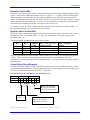
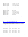
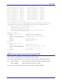
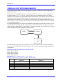
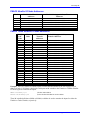
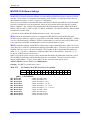
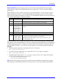
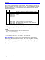
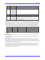
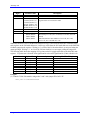
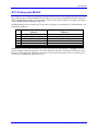
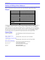
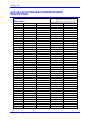
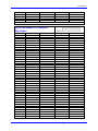
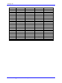
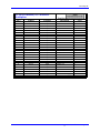
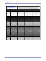
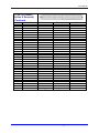
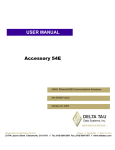
^1
USER MANUAL
^1 USER MANUAL
^2 Accessory 3E
^3 The 144-Bit I/O Board
^4 3Ax-602811-xUxx
^5 October 15, 2003
Single Source Machine Control
Power // Flexibility // Ease of Use
21314 Lassen Street Chatsworth, CA 91311 // Tel. (818) 998-2095 Fax. (818) 998-7807 // www.deltatau.com
Copyright Information
© 2003 Delta Tau Data Systems, Inc. All rights reserved.
This document is furnished for the customers of Delta Tau Data Systems, Inc. Other uses are
unauthorized without written permission of Delta Tau Data Systems, Inc. Information contained in
this manual may be updated from time-to-time due to product improvements, etc., and may not
conform in every respect to former issues.
To report errors or inconsistencies, call or email:
Delta Tau Data Systems, Inc. Technical Support
Phone: (818) 717-5656
Fax: (818) 998-7807
Email: [email protected]
Website: http://www.deltatau.com
Operating Conditions
All Delta Tau Data Systems, Inc. motion controller products, accessories, and amplifiers contain
static sensitive components that can be damaged by incorrect handling. When installing or handling
Delta Tau Data Systems, Inc. products, avoid contact with highly insulated materials. Only
qualified personnel should be allowed to handle this equipment.
In the case of industrial applications, we expect our products to be protected from hazardous or
conductive materials and/or environments that could cause harm to the controller by damaging
components or causing electrical shorts. When our products are used in an industrial environment,
install them into an industrial electrical cabinet or industrial PC to protect them from excessive or
corrosive moisture, abnormal ambient temperatures, and conductive materials. If Delta Tau Data
Systems, Inc. products are directly exposed to hazardous or conductive materials and/or
environments, we cannot guarantee their operation.
Accessory 3E
Table of Contents
INTRODUCTION .....................................................................................................................................................1
HARDWARE SETUP ...............................................................................................................................................3
ACC-3E Board Layout............................................................................................................................................3
ACC-3E Connectors................................................................................................................................................4
ACC-3E 48/96/144-I/O Board Jumpers ..................................................................................................................4
E1-E4: I/O Gate Address Select Jumpers..........................................................................................................4
E1-E4: I/O Gate Address Select Jumpers..........................................................................................................4
USING ACC-3E WITH TURBO UMAC................................................................................................................5
UMAC-Turbo Memory Mapping for ACC-3E .......................................................................................................5
Control Register ......................................................................................................................................................5
Direction Control Bits ........................................................................................................................................6
Register Select Control Bits................................................................................................................................6
Control Word Setup Example .............................................................................................................................6
Accessory 3E I/O M-Variables for UMAC Turbo..................................................................................................7
UMAC Turbo Closed Loop Control Using ACC-3E..............................................................................................8
USING ACC-3E WITH UMAC-MACRO ..............................................................................................................9
MACRO Station I/O Node Transfer Addresses...................................................................................................9
PMAC2 Ultralite I/O Node Addresses..............................................................................................................10
PMAC2 Turbo Ultralite I/O Node Addresses ...................................................................................................10
MACRO I/O Software Setings..............................................................................................................................11
ACC-3E Setup with MACRO ...............................................................................................................................16
Reading and Writing to Node Addresses ..............................................................................................................17
Example:...........................................................................................................................................................17
Example Setup: .................................................................................................................................................17
Active Nodes for Compact MACRO I/O Station ...............................................................................................18
PMAC2 Ultralite Example M-Variable Definitions..............................................................................................19
PMAC2 TURBO Ultralite Example M-Variable Definitions ...............................................................................20
Example 1: 48 Inputs 48 Outputs Using 3×16-Bit Transfers ...............................................................................21
Example 2: 48 Inputs 48 Outputs Using 1×24-Bit Transfers ...............................................................................22
Example 3: 36 Inputs 36 Outputs Using 1×72-Bit Transfer ................................................................................23
ACC-3E 144-I/O PIGGYBACK BOARD HEADER DESCRIPTIONS ............................................................25
J4 (50-Pin Header) I/O Connector Description ...............................................................................................25
J5 (50-Pin Header) I/O Connector Description ...............................................................................................26
J6 (50-Pin Header) I/O Connector Description ...............................................................................................27
J7 (50-Pin Header) I/O Connector Description ...............................................................................................28
J8 (50-Pin Header) I/O Connector Description ...............................................................................................29
J9 (50-Pin Header) I/O Connector Description ...............................................................................................30
J10 (26-Pin Header) I/O Connector Description .............................................................................................32
P1 (96-Pin Header) (Option A Required)........................................................................................................33
Table of Contents
i
Accessory 3E
ii
Table of Contents
Accessory 3E
INTRODUCTION
The PMAC Accessory 3E is a general-purpose I/O board to the PMAC2 Ultralite via the MACRO
Station. ACC-3E provides up to 144-bits lines of digital I/O. The actual I/O Reads are carried out using
M-variables like other tradition PMAC products. ACC-3E is one of the series of MACRO Stack
accessories designed to transfer data to the MACRO-Station through its JEXP port pins plugged directly
into the stack. The other boards in the family of MACRO accessories are:
ACC-1E
ACC-2E
ACC-3E
ACC-4E
ACC-6E
Introduction
2-axis Expansion Card
4-Axis Expansion Card
up to 144-bits TTL level I/O
48-bits optically isolated I/O
8-16 channels 12-bit A/D Converters
Accessory 3E
2
Introduction
Accessory 3E
HARDWARE SETUP
The ACC-3E uses expansion port memory locations defined by the type of PMAC (3U Turbo or MACRO
Station) it is directly communicating to. These memory locations are typically used with other Delta Tau
3U I/O accessories such as:
ACC-4E
ACC-6E
24 inputs and 24 outputs, low power, all optically isolated
16 channels 12-bit ADC
All of these accessories have settings which tell them where the information is to be processed at either
the PMAC 3U Turbo or the MACRO Station.
3U Turbo PMAC
Memory Locations
MACRO Station
Memory Locations
$078800
$078900
$078A00
$078B00
$FFC0
$FFC8
$FFD0
$FFD8
The ACC-3E has a set of jumers (E1 through E4) telling it where to process its data Once the information
is at these locations, we can process the binary word in the encoder conversion table to use for servo loop
closure. Proper setting of the dip-switches ensures all of the JEXP boards used in the application do not
interfere with each other.
ACC-3E Board Layout
Hardware Setup
3
Accessory 3E
ACC-3E Connectors
J1: (JEXP_A) 40-pin header for connection to piggyback board(s)
J2: (JEXP_B) 40-pin header for connection to piggyback board(s)
J3: (JEXP_C) 28-pin header for connection to piggyback board(s)
J4: 50-pin IDC header for connection of I/O00 to I/O23 to Opto-22 G4PB24 or equivalent I/O board with
straight-across connector (Option A required)
J5: 50-pin IDC header for connection of I/O24 to I/O47 to Opto-22 G4PB24 or equivalent I/O board with
straight-across connector (Option A required)
J6: 50-pin IDC header for connection of I/O48 to I/O71 to Opto-22 G4PB24 or equivalent I/O board with
straight-across connector (Option B required)
J7: 50-pin IDC header for connection of I/O72 to I/O95 to Opto-22 G4PB24 or equivalent I/O board with
straight-across connector (Option B required)
J8: 50-pin IDC header for connection of I/O96 to I/O119 to Opto-22 G4PB24 or equivalent I/O board
with straight-across connector (Option C required)
J9: 50-pin IDC header for connection of I/O120 to I/O143 to Opto-22 G4PB24 or equivalent I/O board
with straight-across connector (Option C required)
J10: 26-pin IDC header for connection of optically isolated outputs for I/O120 to I/O127; and optically
isolated inputs for I/O128 to I/O143 (Option C1 or C2 required).
P1: 96-pin DIN connector for connection of I/O00 to I/O47 (Option A required)
TB1: 2-pin terminal block for 5V power supply
ACC-3E 48/96/144-I/O Board Jumpers
UMAC
TURBO
E1
E2
E3
E4
1-2
1-2
1-2
1-2
$FFC0-$FFC7
$FFC8-$FFCF
$FFD0-$FFD7
$FFD8-$FFDF
$078800-$078807
$078900-$078907
$078A00-$078A07
$078B00-$078B07
E4
UMAC
MACRO
E3
Setting
E2
Jumper
E1
E1-E4: I/O Gate Address Select Jumpers
Note:
Only one of E1 to E4 may be ON on any board. If more than one of these boards
is used in a given UMAC-MACRO or UMAC Turbo, each must have a different
jumper ON.)
E1-E4: I/O Gate Address Select Jumpers
Jump pins 1 and 2 to latch inputs on the SERVO clock
Jump pins 2 and 3 to latch inputs on the PHASE clock (default)
4
Hardware Setup
Accessory 3E
USING ACC-3E WITH TURBO UMAC
For the UMAC-Turbo, the ACC-3E can be used for either general purpose I/O or as latched inputs for
servo loop position or velocity feedback. The registers used for general I/O use are 8-bit registers and the
user will define three 8-bit registers for each 24-bit I/O port. To use the ACC-3E for closed loop servo
data the user must setup various I-variables for the encoder conversion table and power-on position. The
encoder conversion table is setup using variables I8000 through I8192. Each variable is an entry in the
conversion table and it’s setup is described in the TURBO PMAC Software Reference Manual.
UMAC-Turbo Memory Mapping for ACC-3E
The Dalta Tau I/O Gate used on the ACC-3E is an 8-bit processor and therefore the memory mapping to
the I/O bits is processed as 8-bit words at the Turbo UMAC. Using this simple scheme the user could
process up to 576 (144×4) bits of data for general purpose I/O.
Jumper E1
Jumper E2
Jumper E3
Jumper E4
Description
Y:$078800,0,8
Y:$078801,0,8
Y:$078802,0,8
Y:$078803,0,8
Y:$078804,0,8
Y:$078805,0,8
Y:$078807,0,8
Y:$078800,8,8
Y:$078801,8,8
Y:$078802,8,8
Y:$078803,8,8
Y:$078804,8,8
Y:$078805,8,8
Y:$078807,8,8
Y:$078800,16,8
Y:$078801,16,8
Y:$078802,16,8
Y:$078803,16,8
Y:$078804,16,8
Y:$078805,16,8
Y:$078807,16,8
Y:$078900,0,8
Y:$078901,0,8
Y:$078902,0,8
Y:$078903,0,8
Y:$078904,0,8
Y:$078905,0,8
Y:$078907,0,8
Y:$078900,8,8
Y:$078901,8,8
Y:$078902,8,8
Y:$078903,8,8
Y:$078904,8,8
Y:$078905,8,8
Y:$078907,8,8
Y:$078900,16,8
Y:$078901,16,8
Y:$078902,16,8
Y:$078903,16,8
Y:$078904,16,8
Y:$078905,16,8
Y:$078907,16,8
Y:$078A00,0,8
Y:$078A01,0,8
Y:$078A02,0,8
Y:$078A03,0,8
Y:$078A04,0,8
Y:$078A05,0,8
Y:$078A07,0,8
Y:$078A00,8,8
Y:$078A01,8,8
Y:$078A02,8,8
Y:$078A03,8,8
Y:$078A04,8,8
Y:$078A05,8,8
Y:$078A07,8,8
Y:$078A00,16,8
Y:$078A01,16,8
Y:$078A02,16,8
Y:$078A03,16,8
Y:$078A04,16,8
Y:$078A05,16,8
Y:$078A07,16,8
Y:$078B00,0,8
Y:$078B01,0,8
Y:$078B02,0,8
Y:$078B03,0,8
Y:$078B04,0,8
Y:$078B05,0,8
Y:$078B07,0,8
Y:$078B00,8,8
Y:$078B01,8,8
Y:$078B02,8,8
Y:$078B03,8,8
Y:$078B04,8,8
Y:$078B05,8,8
Y:$078B07,8,8
Y:$078B00,16,8
Y:$078B01,16,8
Y:$078B02,16,8
Y:$078B03,16,8
Y:$078B04,16,8
Y:$078B05,16,8
Y:$078B07,16,8
I/O bits 0-7 (J4)
I/O bits 8-15(J4)
I/O bits 16-23 (J4)
I/O bits 24-31 (J5)
I/O bits 32-39(J5)
I/O bits 40-47 (J5)
Control Word
I/O bits 0-7 (J6)
I/O bits 8-15(J6)
I/O bits 16-23 (J6)
I/O bits 24-31 (J7)
I/O bits 32-39(J7)
I/O bits 40-47 (J7)
Control Word
I/O bits 0-7 (J8)
I/O bits 8-15(J8)
I/O bits 16-23 (J8)
I/O bits 24-31 (J9)
I/O bits 32-39(J9)
I/O bits 40-47 (J9)
Control Word
Because the data processed at these I/O Gate Arrays are extremely fast, the user were to map the machine
I/O to the ACC-3E memory locations, they could do ao bit wise or using 8-bit words.
Control Register
The control register at address {Base + 7} permits the configuration of the IOGATE IC to a variety of
applications. The control register consists of eight write/read-back bits – Bits 0 - 7. The control register
consists of two sections; Direction Control and Register Select.
The direction control allows the user to set his/her input bytes to be read only. One of the advantages of
the IOGATE IC is that we give the user the ability to define the bits as inputs or outputs. This “control”
mechanism allows the user to ensure the inputs will always be read properly. Our traditional I/O
accessories always define the inputs and outputs by hardware.
The register select bits allow the user to define the input or output bytes inversion control or the latching
input features.
Using Acc-3E with Turbo UMAC
5
Accessory 3E
Direction Control Bits
Bits 0 to 5 of the control register simply control the direction of the I/O for the matching numbered data
register. That is, Bit n controls the direction of the I/O at {Base + n}. A value of 0 in the control bit (the
default) permits a write operation to the data register, enabling the output function for each line in the
register. Enabling the output function does not prevent the use of any or all of the lines as inputs, as long
as the outputs are off (non-conducting). A value of 1 in the control bit does not permit a write operation
to the data register, disabling the output, reserving the register for inputs.
For example, a value of 1 in Bit 3 disables the write function into the data register at address {Base + 3},
ensuring that lines IO24 - IO31 can always be used as inputs.
Register Select Control Bits
Bits 6 and 7 of the control register together select which of 4 possible registers can be accessed at each of
the addresses {Base + 0} through {Base + 5}. They also select which of 2 possible registers can be
selected at {Base + 6}.
The following table explains how these bits select registers:
Bit 7
Bit 6
Combined
Value
0
0
1
1
0
1
0
1
0
1
2
3
{Base + 0} to {Base + 5}
Register Selected
{Base + 6} Register
Selected
Data Register
Setup Register 1
Setup Register 2
Setup Register 3
Data Register
Setup Register
n. a.
n. a.
In a typical application, non-zero combined values of Bits 6 and 7 are only used for initial configuration
of the IC. These values are used to access the setup registers at the other addresses After the
configuration is finished, zeros are written to both Bits 6 and 7, so the data registers at the other registers
can be accessed.
Control Word Setup Example
The user will need to setup the control words for the IO card at power up. A simple plc could be written
to setup the control word properly could accomplish this task. For this example, we will be setting up one
ACC-3E (IC0 48in/48out) and one ACC4E (IC1 - 24in/24out)
Control Word for ACC-3E (M2007->Y:$078807,0,8)
Hex ($)
Binary
Bit
0
0
7
0
6
1
5
1
4
7
1
3
1
2
1
1
1
0
Bits 0-7 are read only
Bits 8-15 are read only
Bits 16-23 are read only
Register
Select
M2000->Y:$078800,0,8
6
Bits 24-31 read only
Bits 32-39 read only
Bits 40-47 read only
;I/O bits 0-7 (port A IC0)
Using Acc-3E with Turbo UMAC
Accessory 3E
M2001->Y:$078801,0,8
M2002->Y:$078802,0,8
M2003->Y:$078803,0,8
M2004->Y:$078804,0,8
M2005->Y:$078805,0,8
M2006->Y:$078806,0,8
M2007->Y:$078807,0,8
;I/O bits 8-15 (port A IC0)
;I/O bits 16-23 (port A IC0)
;I/O bits 0-7 (port B IC0)
;I/O bits 8-15 (port B IC0)
;I/O bits 16-23 (port B IC0)
;register selected
;control register
M2008->Y:$078800,8,8
M2009->Y:$078801,8,8
M2010->Y:$078802,8,8
M2011->Y:$078803,8,8
M2012->Y:$078804,8,8
M2013->Y:$078805,8,8
M2014->Y:$078806,8,8
M2015->Y:$078807,8,8
;I/O bits 0-7 (port A IC1)
;I/O bits 8-15 (port A IC1)
;I/O bits 16-23 (port A IC1)
;I/O bits 0-7 (port B IC1)
;I/O bits 8-15 (port B IC1)
;I/O bits 16-23 (port B IC1)
;register selected
;control register
M2016->Y:$078800,16,8
M2017->Y:$078801,16,8
M2018->Y:$078802,16,8
M2019->Y:$078803,16,8
M2020->Y:$078804,16,8
M2021->Y:$078805,16,8
M2022->Y:$078806,16,8
M2023->Y:$078807,16,8
;I/O bits 0-7 (port A IC2)
;I/O bits 8-15 (port A IC2)
;I/O bits 16-23 (port A IC2)
;I/O bits 0-7 (port B IC2)
;I/O bits 8-15 (port B IC2)
;I/O bits 16-23 (port B IC2)
;register selected
;control register
M2007->Y:078C07,0,8
M2015->Y:078C07,8,8
M2023->Y:078C07,16,8
;control word for $78C00,0,8 - $78C05,0,8
;control word for $78C00,8,8 - $78C05,8,8
;control word for $78C00,16,8 -$78C05,16,8
;**** PLC to initialize
OPEN PLC 1 CLEAR
M2007=$3F
M2015=$00
M2023=$07
DIS PLC1
CLOSE
read/write I/O bits ****
;define bits 0-23 and 24-47 as inputs (ACC-3E)
;define bits 0-23 and 24-47 as outputs (ACC-3E)
;define bits 0-23 as inputs and bits 24-47 as outputs (ACC-4E)
Accessory 3E I/O M-Variables for UMAC Turbo
The following is a list of suggested M-variables for the default jumper settings is provided. You may
assign any M-variables to these addresses. For this example we are assuming 24 inputs and 24 outputs.
The user may make these M-variable definitions and use them as general purpose I/O for their PLC’s or
motion programs.
M7000->Y:$079C00,0,1
M7001->Y:$079C00,1,1
M7002->Y:$079C00,2,1
M7003->Y:$079C00,3,1
M7004->Y:$079C00,4,1
M7005->Y:$079C00,5,1
M7006->Y:$079C00,6,1
M7007->Y:$079C00,7,1
M7008->Y:$079C01,0,1
M7009->Y:$079C01,1,1
M7010->Y:$079C01,2,1
M7011->Y:$079C01,3,1
M7012->Y:$079C01,4,1
M7013->Y:$079C01,5,1
Input
Input
Input
Input
Input
Input
Input
Input
Input
Input
Input
Input
Input
Input
Using Acc-3E with Turbo UMAC
0
1
2
3
4
5
6
7
8
9
10
11
12
13
M7024->Y:$079C03,0,1
M7025->Y:$079C03,1,1
M7026->Y:$079C03,2,1
M7027->Y:$079C03,3,1
M7028->Y:$079C03,4,1
M7029->Y:$079C03,5,1
M7030->Y:$079C03,6,1
M7031->Y:$079C03,7,1
M7032->Y:$079C04,0,1
M7033->Y:$079C04,1,1
M7034->Y:$079C04,2,1
M7035->Y:$079C04,3,1
M7036->Y:$079C04,4,1
M7037->Y:$079C04,5,1
Output
Output
Output
Output
Output
Output
Output
Output
Output
Output
Output
Output
Output
Output
0
1
2
3
4
5
6
7
8
9
10
11
12
13
7
Accessory 3E
M7014->Y:$079C01,6,1
M7015->Y:$079C01,7,1
M7016->Y:$079C02,0,1
M7017->Y:$079C02,1,1
M7018->Y:$079C02,2,1
M7019->Y:$079C02,3,1
M7020->Y:$079C02,4,1
M7021->Y:$079C02,5,1
M7022->Y:$079C02,6,1
M7023->Y:$079C02,7,1
Input
Input
Input
Input
Input
Input
Input
Input
Input
Input
14
15
16
17
18
19
20
21
22
23
M7038->Y:$079C04,6,1
M7039->Y:$079C04,7,1
M7040->Y:$079C05,0,1
M7041->Y:$079C05,1,1
M7042->Y:$079C05,2,1
M7043->Y:$079C05,3,1
M7044->Y:$079C05,4,1
M7045->Y:$079C05,5,1
M7046->Y:$079C05,6,1
M7047->Y:$079C05,7,1
Output
Output
Output
Output
Output
Output
Output
Output
Output
Output
14
15
16
17
18
19
20
21
22
23
;****** Sample E-Stop PLC *****
; This PLC will abort all motion programs and kill the bus voltage to
; the motors when E-stop is depressed. When E-Stop button in pulled out
; the motors will servo to actual position (<ctrl> A command) after
; allowing 5 seconds for proper bus voltage.
;
;
;
;
P7000
M7000
M7024
I5111
used
used
used
used
as a Latch variable
Emergancy Stop Input
as Main Contact for main AC for Bus Voltage
as count down timer
OPEN PLC 5 CLEAR
IF (M7000=1 and P7000=0)
CMD^A
I5111=500*8388608/I10
WHILE (I5111>0) ENDWHILE
CMD^K
M7024=0
P7000=1
Endif
IF (M7000=0 and P7000=1)
M7024=1
I5111=5000*8388608/I10
WHILE (I5111>0) ENDWHILE
CMD^A
P7000=0
Endif
;emergancy stop condition
;global motion program abort
;500 msec delay for deceleration
;kill all axes
;turn off BUS voltage
;latch input
;enable BUS volatge
;5000 msec delay for bus voltage
;close loop for all servos
;latch input
close
UMAC Turbo Closed Loop Control Using ACC-3E
The ACC-3E data can also be used for closed loop control. The encoder conversion table at the UMACTurbo will have to be modified to use the data for closed loop control.
Example: E2 is jumpered on the ACC-3E to select the I/O Gate address (Y:$078900-Y:$78907)
Set:
I8000 =$F78900
;turbo location $3501 process Y:$078900 as parallel 3U format
I8001 =$018000
;turbo location $3502 for 24-bit Y register
The user can then set Ix03 and Ix04 to $3502 to use the data for parallel feedback.
8
Using Acc-3E with Turbo UMAC
Accessory 3E
USING ACC-3E WITH UMAC-MACRO
A fundamental understanding of the MACRO Station I/O transfer is needed to set up the MACRO I/O
family of accessories.
The MACRO station typically will have up to eight axis nodes (0, 1, 4, 5, 8, 9, 12, and 13) and up to six
I/O transfer nodes (2, 3, 6, 7, 10, and 11). There are three types of I/O transfers allowed to send the
information to the Ultralite from the MACRO-Station: 48-bit transfer, 24-bit transfer, and 72-bit transfer.
The PMAC2 Ultralite and the MACRO-Station enable the user to transfer 72 bits per I/O node. For a
multi Master system, 432 bits (6×72) of data may be transferred for each Master (Ultralite) in the ring. If
only one Master is used in the ring, node 14 could be used for I/O transfer, which would give us 504 bits
(7×72) of I/O transfer data.
For all MACRO-Station I/O accessories, the information is transferred to or from the accessory I/O Gate
to the MACRO-Station CPU Gate 2B. Information from the MACRO-Station Gate 2B is then read or
written directly to the MACRO IC on the Ultralite. Once the information is at the Ultralite, it can be used
in the users application motion programs or PLC programs.
Ultralite
MACRO IC
MACRO Station
Gate 2B
I/O Accessory
Gate
Each I/O board has jumper and software settings to select the I/O transfer memory locations at both the
I/O transfer Gate and the MACRO transfer addresses. These jumpers and software settings are discussed
in this manual.
MACRO I/O Gate Locations for ACC3E and ACC4E
$FFC0, $FFC2, $FFC4
$FFC8, $FFCA, $FFCC
$FFD0, $FFD2, $FFD4
$FFD8, $FFDA, $FFDC
MACRO Station I/O Node Transfer Addresses
Node(s)
Node 24-bit: Transfer
Addresses
Node 16-bit (upper 16 bits): Transfer
Addresses
2
3
6
7
10
11
X:$C0A0
X:$C0A4
X:$C0A8
X:$C0AC
X:$C0B0
X:$C0B4
X:$C0A1, X:$C0A2, X:$C0A3
X:$C0A5, X:$C0A6, X:$C0A7
X:$C0A9, X:$C0AA, X:$C0AB
X:$C0AD, X:$C0AE, X:$C0AF
X:$C0B1, X:$C0B2, X:$C0B3
X:$C0B5, X:$C0B6, X:$C0B7
Using Acc-3E with Turbo UMAC
9
Accessory 3E
PMAC2 Ultralite I/O Node Addresses
Node
Node 24-bit: Transfer
Addresses
Node 16-bit (upper 16 bits): Transfer
Addresses
2
3
6
7
10
11
X:$C0A0
X:$C0A4
X:$C0A8
X:$C0AC
X:$C0B0
X:$C0B4
X:$C0A1, X:$C0A2, X:$C0A3
X:$C0A5, X:$C0A6, X:$C0A7
X:$C0A9, X:$C0AA, X:$C0AB
X:$C0AD, X:$C0AE, X:$C0AF
X:$C0B1, X:$C0B2, X:$C0B3
X:$C0B5, X:$C0B6, X:$C0B7
PMAC2 Turbo Ultralite I/O Node Addresses
MACR
O IC
Node
User
Node
Node 24-bit
Transfer
Addresses
Node 16-bit (upper 16 bits)
Transfer Addresses
(IC0 ) 2
(IC0) 3
(IC0) 6
(IC0) 7
(IC0) 10
(IC0) 11
(IC1) 2
(IC1) 3
(IC1) 6
(IC1) 7
(IC1) 10
(IC1) 11
(IC2 ) 2
(IC2) 3
(IC2) 6
(IC2) 7
(IC2) 10
(IC2) 11
(IC3) 2
(IC3) 3
(IC3) 6
(IC3) 7
(IC3) 10
(IC3) 11
2
3
6
7
10
11
18
19
22
23
26
27
34
35
38
39
42
43
50
51
54
55
58
59
X:$078420
X:$078424
X:$078428
X:$07842C
X:$078430
X:$078434
X:$079420
X:$079424
X:$079428
X:$07942C
X:$079430
X:$079434
X:$078420
X:$07A424
X:$07A428
X:$07A42C
X:$07A430
X:$07A434
X:$07B420
X:$07B424
X:$07B428
X:$07B42C
X:$07B430
X:$07B434
X:$078421, X:$078422, X:$078423
X:$078425, X:$078426, X:$078427
X:$078429, X:$07842A, X:$07842B
X:$07842D, X:$07842E, X:$07842F
X:$078431, X:$078432, X:$078433
X:$078435, X:$078436, X:$078437
X:$079421, X:$079422, X:$079423
X:$079425, X:$079426, X:$079427
X:$079429, X:$07942A, X:$07942B
X:$07942D, X:$07942E, X:$07942F
X:$079431, X:$079432, X:$079433
X:$079435, X:$079436, X:$079437
X:$07A421, X:$07A422, X:$07A423
X:$07A425, X:$07A426, X:$07A427
X:$07A429, X:$07A42A, X:$07A42B
X:$07A42D, X:$07A42E, X:$07A42F
X:$07A431, X:$07A432, X:$07A433
X:$07A435, X:$07A436, X:$07A437
X:$07B421, X:$07B422, X:$07B423
X:$07B425, X:$07B426, X:$07B427
X:$07B429, X:$07B42A, X:$07B42B
X:$07B42D, X:$07B42E, X:$07B42F
X:$07B431, X:$07B432, X:$07B433
X:$07B435, X:$07B436, X:$07B437
Example: If the user wanted to read the inputs from the MACRO Station of the first 24-bit I/O node
address of node 2 (X:$C0A0), then he/she could point an M-variable to the Ultralite or TURBO Ultralite
I/O node registers to monitor the inputs.
M980->X:$C0A0,0,24
M7000->X:$078420,0,24
;Ultralite node2 address
;Turbo Ultralite MACRO IC0 node 2 address
These M-variable definitions (M980 or M1980) could then be used to monitor the inputs for either the
Ultralite or Turbo Ultralite, respectively.
10
Using Acc-3E with Turbo UMAC
Accessory 3E
MACRO I/O Software Setings
The MACRO-Station I/O can be configured as either an input or an output. The hardware connected to
the MACRO I/O boards determines whether or not the addresses defined are inputs or outputs. Each I/O
node has 72-bits of data to be transferred automatically to the Ultralite. As stated previously, there are
three methods of transfer: 3×16-bit, 1×24-bit, or 72-bit transfer.
There are several variables at the MACRO-Station and PMAC2 Ultralite that enable the I/O data transfer.
Once these variables are set to the appropriate values, the user can then process the data like a normal
PMAC or PMAC2. The variables to be modified at the MACRO-Station are MI19, MI69, MI70, MI71,
MI169*, MI170*, MI171*, MI172*, MI173*, MI975, and MI996. The Ultralite must have I996 modified
to enable the I/O nodes used.
* Can only be used with MACRO-Station firmware version 1.112 or greater
MI19 controls the data transfer period on a Compact MACRO Station between the MACRO node
interface registers and the I/O registers, as specified by station MI-variables MI20 through MI71. If MI19
is set to 0, this data transfer is disabled. If MI19 is greater than 0, its value sets the period in Phase clock
cycles (the same as MACRO communications cycles) at which the transfer is done.
MI975 permits the enabling of MACRO I/O nodes on the Compact MACRO Station. MI975 is a 16-bit
value (bits 0 to 15) with bit n controlling the enabling of MACRO node n. If the bit is set to 0, the node is
disabled; if the bit is set to 1, the node is enabled. The I/O nodes on the Compact MACRO Station are
nodes 2, 3, 6, 7, 10, and 11, which can be enabled by MI975 bits of these numbers. Only bits 2, 3, 6, 7,
10, and 11 of MI975 should ever be set to 1.
MI975 is used at the power-on/reset of the Compact MACRO Station in combination with rotary switch
SW1 and MI976 to determine which MACRO nodes are to be enabled. The net result can be read in
Station variable MI996. To get a value of MI975 to take effect, the value must be saved
(MSSAVE{node}) and the Station reset (MS$$${node}).
Example: Set MI975 to enable nodes 2 and 3
MS0, I975
Set Number MACRO IO nodes to be enabled
15 14 13 12 11 10
Bit
Value 0 0 0 0 0 0
9
0
8
0
7
0
6
0
5
0
4
0
3
1
2
1
1
0
0
0
∴MS0, i975=$000C
MS0,MI975=$4
MS0,MI975=$C
MS0,MI975=$4C
MS0,MI975=$CC
MS0,MI975=$4CC
MS0,MI975=$CCC
MS4,MI975=$40
MS4,MI975=$C0
MS8,MI975=$400
MS8,MI975=$C00
Using Acc-3E with Turbo UMAC
; Enable I/O Node 2 alone
; Enable I/O Nodes 2 & 3
; Enable I/O Nodes 2, 3, & 6
; Enable I/O Nodes 2, 3, 6, & 7
; Enable I/O Nodes 2, 3, 6, 7, & 10
; Enable I/O Nodes 2, 3, 6, 7, 10, & 11
; Enable I/O Node 6 alone
; Enable I/O Nodes 6 & 7
; Enable I/O Node 10 alone
; Enable I/O Nodes 10 & 11
11
Accessory 3E
MI69 and MI70 specify the registers used in 16-bit I/O transfers between MACRO node interface
registers and I/O registers on the MACRO Station I/O accessory board. They are used only if MI19 is
greater than 0.
MI69 and MI70 are 48-bit variables represented as 12 hexadecimal digits. The first 6 digits specify the
number and address of 48-bit (3 x 16) real-time MACRO-node register sets to be used. The second 6
digits specify the number and address of 16-bit I/O sets on the MACRO Station I/O accessory board to be
used. The individual digits are specified as follows:
Digit
#
Possible Values
Description
1
0, 1, 2, 3
2
3-6
0
$C0A1 (Node 2),
$C0A5 (Node 3),
$C0A9 (Node 6),
$C0AD (Node 7),
$C0B1 (Node 10),
$C0B5 (Node 11)
0, 1, 2, 3
0
$FFC0, $FFC8,
$FFD0, $FFD8
$FFE0, $FFE8
$FFF0, $FFF8
Number of MACRO I/O nodes to use (0 disables); this should also match
the number of 48-bit I/O sets you intend to use (see Digit 7)
(Reserved for future use)
MACRO Station X Address of MACRO I/O node first of three 16-bit
registers
7
8
9-12
Number of 16-bit I/O sets to use (1x16, 2x16, 3x16; 0 disables)
(Reserved for future use)
MACRO Station Y Base Address of I/O Board as set by Board Jumper
E1-E4 (ACC-3E board) or E15-E18 (ACC-4E board)
MACRO Station Y Base Address of ACC-9E, ACC-10E, ACC-11E,
ACC-12E and ACC-13E
When this function is active, the MACRO Station will copy values from the MACRO command (input)
node registers to the I/O board addresses; it will copy values from the I/O board addresses to the MACRO
feedback (output) node registers. Writing a ‘0’ to a bit of the I/O board enables it as an input, letting the
output pull high. Writing a ‘1’ to a bit of the I/O board enables it as an output and pulls the output low.
Example:
1. 48 bit I/O transfer using node 2 with jumper E2 of ACC-3E selected
MS0, MI69=$10C0A130FFC8
2. (2) 96 bit I/O transfer using nodes 2 & 3, jumper E2 of ACC-3E (72 inputs, 24 outputs),
MS0, MI69=$20C0A130FFC8
3. 244 bit I/O transfer using nodes 2, 3, 6, 7, 10, and 11, using two ACC-3Es. Jumper E2 on the first
ACC3E and E3 jumpered on the second ACC3E.
MS0, MI69=$30C0A130FFC8
MS0, MI70=$30C0AD30FFD0
MI71 specifies the registers used in 24-bit I/O transfers between MACRO I/O node interface registers
and I/O registers on the MACRO Station I/O accessory board. It is used only if MI19 is greater than 0.
12
Using Acc-3E with Turbo UMAC
Accessory 3E
MI71 is a 48-bit variable represented as 12 hexadecimal digits. The first 6 digits specify the number and
address of 48-bit real-time MACRO-node register sets to be used. The second 6 digits specify the number
and address of 48-bit I/O sets on the MACRO Station I/O accessory board to be used. The individual
digits are specified as follows:
Digit #
Possible Values
1
0, 1, 2, 3
2
3-6
0
$C0A0 (Node 2),
$C0A4 (Node 3),
$C0A8 (Node 6),
$C0AC (Node 7),
$C0B0 (Node 10),
$C0B4 (Node 11)
0, 1, 2
0
$FFC0, $FFC8,
$FFD0, $FFD8
$FFE0, $FFE8
$FFF0, $FFF8
7
8
9-12
Description
Number of MACRO I/O nodes to use times 2 (0 disables); this should
also match the number of 48-bit I/O sets you intend to use (see Digit 7)
(Reserved for future use)
MACRO Station X Address of MACRO I/O node first of three 16-bit
registers
Number of 24-bit I/O sets to use (1x24, 2x24; 0 disables)
(Reserved for future use)
MACRO Station Y Base Address of I/O Board as set by Board Jumper
E1-E4 (ACC-3E board) or E15-E18 (ACC-4E board)
MACRO Station Y Base Address of ACC-9E, ACC-10E, ACC-11E,
ACC-12E and ACC-13E
When this function is active, the MACRO Station will copy values from the MACRO command (input)
node registers to the I/O board addresses; it will copy values from the I/O board addresses to the MACRO
feedback (output) node registers. Writing a ‘0’ to a bit of the I/O board enables it as an input, letting the
output pull high. Writing a ‘1’ to a bit of the I/O board enables it as an output and pulls the output low.
Example:
1. Two 24-bit I/O transfers using nodes 2 and 3 with jumper E2 selected
MS0, MI71=$10C0A020FFC8
2. 96 bit I/O transfer using nodes 2, 3, 6, and 7, jumper E2 of ACC-3E
MS0, MI71=$20C0A020FFC8
3. 144 bit I/O transfer using nodes 2, 3, 6, 7, 10, and 11, using two ACC-3Es.
MS0, MI71=$30C0A020FFC8
MI169 and MI170 specify the registers used in 72-bit I/O transfers between one MACRO node
interface register and I/O registers on a MACRO station. They are used only if MI19 is greater than 0.
MI169 and MI170 are 48-bit variables represented as 12 hexadecimal digits. The first 6 digits specify the
address of 72-bit (24 & 3 x 16-bit) real-time MACRO-node register to be used. The second 6 digits
specify the address of the LOWER I/O Gate on an Option 3 or Option 4 board to be used. The individual
digits are specified as follows:
Using Acc-3E with Turbo UMAC
13
Accessory 3E
Digit #
Possible Values
1
2
3-6
0
0
$C0A0 (Node 2),
$C0A4 (Node 3),
$C0A8 (Node 6),
$C0AC (Node 7),
$C0B0(Node 10),
$C0B4 (Node 11)
0
0
$FFC0, $FFC8,
$FFD0, $FFD8
$FFE0, $FFE8
$FFF0, $FFF8
7
8
9-12
Description
(Reserved for future use)
(Reserved for future use)
MACRO Station X Address of MACRO I/O node 24-bit register.
(Reserved for future use)
(Reserved for future use)
MACRO Station Y Base Address of I/O Board as set by Board Jumper
E1-E4 (ACC-3E board) or E15-E18 (ACC-4E board)
MACRO Station Y Base Address of ACC-9E, ACC-10E, ACC-11E,
ACC-12E and ACC-13E
When this function is active, the MACRO Station will copy values from the MACRO command (input)
node registers to the I/O board addresses; it will copy values from the I/O board addresses to the MACRO
feedback (output) node registers. Writing a ‘0’ to a bit of the I/O board enables it as an input, letting the
output pull high. Writing a ‘1’ to a bit of the I/O board enables it as an output and pulls the output low.
The following table shows the mapping of I/O points on the I/O piggyback boards to the MACRO node
registers. I/O points move from the least significant bit to the most significant bit (I/O00 at Node bit 0).
I/O Point #s
Option 3 Part
Present on Option 4?
Matching MACRO X Register
I/O00 - I/O15
I/O16 - I/O31
I/O32 - I/O47
I/O48 - I/O71
Sub-option A
Sub-option A
Sub-option A
Sub-option B
Yes
Yes
Yes
No
Specified MACRO X Address + 1
Specified MACRO X Address + 2
Specified MACRO X Address + 3
Specified MACRO X Address + 0
Examples:
I169=$00C0A000FFC0 transfers 72-bit I/O between an I/O board set at $FFC0 and MACRO Nodes 2
($C0A0-$C0A3)
I169=$00C0B000FFC8 transfers 72-bit I/O between an I/O board set at $FFC8 and MACRO Node 10
($C0B0-$C0B3).
MI171, MI172 or MI173 specifies the registers used in 144-bit I/O transfers between MACRO I/O
node interface registers and I/O registers on a MACRO station. It is used only if MI19 is greater than 0.
The transfer utilizes two consecutive 72-bit X: memory I/O nodes. The three 48-bit I/O Gates must be the
LOWER, MIDDLE and UPPER configuration.
MI171, MI172 or MI173 is a 48-bit variable represented as 12 hexadecimal digits. The first 6 digits
specify the address of the first 72-bit real-time MACRO-node register sets to be used of the two. The
second 6 digits specify the address of 48-bit I/O sets on an Option 3 or Option 4 board to be used. The
individual digits are specified as follows:
14
Using Acc-3E with Turbo UMAC
Accessory 3E
Digit #
Possible Values
1
2
3-6
0
0
$C0A0 (Nodes 2,3),
$C0A4 (Nodes 3,6),
$C0A8 (Nodes 6,7),
$C0AC (Nodes 7,10),
$C0B0 (Nodes 10,11),
$C0B4 (Nodes 11,14)
0
0
$FFC0, $FFC8,
$FFD0, $FFD8
$FFE0, $FFE8
$FFF0, $FFF8
7
8
9-12
Description
(Reserved for future use)
(Reserved for future use)
MACRO Station X Address of MACRO I/O first 24-bit
register of the two consecutive nodes
(Reserved for future use)
(Reserved for future use)
MACRO Station Y Base Address of I/O Board as set by
Board Jumper E1-E4 (ACC-3E board) or E15-E18 (ACC-4E
board)
MACRO Station Y Base Address of ACC-9E, ACC-10E,
ACC-11E, ACC-12E and ACC-13E
When this function is active, the MACRO Station will copy values from the MACRO command (input)
node registers to the I/O board addresses; it will copy values from the I/O board addresses to the MACRO
feedback (output) node registers. Writing a ‘0’ to a bit of the I/O board enables it as an input, letting the
output pull high. Writing a ‘1’ to a bit of the I/O board enables it as an output, pulling the output low.
The following table shows the mapping of I/O points on the I/O piggyback boards to the MACRO node
registers. I/O points move from the least significant bit to the most significant bit (I/O00 at Node bit 0).
I/O Point #s
Option 3 Part
Present on Option 4?
I/O00 - I/O15
I/O16 - I/O31
I/O32 - I/O47
I/O48 - I/O63
I/O64 - I/O79
I/O80 - I/O95
I/O96 - I/O119
I/O120 - I/O143
Sub-option A
Sub-option A
Sub-option A
Sub-option B
Sub-option B
Sub-option B
Sub-option C
Sub-option C
Yes
Yes
Yes
No
No
No
No
No
Matching MACRO X Register
Specified MACRO X Address + 1
Specified MACRO X Address + 2
Specified MACRO X Address + 3
Specified MACRO X Address + 5
Specified MACRO X Address + 6
Specified MACRO X Address + 7
Specified MACRO X Address + 0
Specified MACRO X Address + 4
Example:
(1) Transfer 72-bits I/O transfers using nodes 2 and 3 with jumper E2 of ACC-3E
MS0, MI171=$00C0A000FFC8
Using Acc-3E with Turbo UMAC
15
Accessory 3E
ACC-3E Setup with MACRO
Normally, the user will have a PLC to read the input word and write to the output word based on the input
logic of the program. With the MACRO I/O interface, this can also be accomplished by either using the
48-bit transfer, 24-bit transfer, or 72-bit transfer. These words would be defined as an input word, output
word, or in/out word (combination of the two).
With the MACRO I/O Accessories, the 72-bit word is split into 3×16-bit transfers, 1×24-bit transfers, or a
combination of the two.
Node
Node 24-bit: Transfer
Addresses
Node 16-bit (upper 16 bits): Transfer
Addresses
2
3
6
7
10
11
X:$C0A0
X:$C0A4
X:$C0A8
X:$C0B0
X:$C0B4
X:$C0B8
X:$C0A1, X:$C0A2, X:$C0A3
X:$C0A5, X:$C0A6, X:$C0A7
X:$C0A9, X:$C0AA, X:$C0AB
X:$C0B1, X:$C0B2, X:$C0B3
X:$C0B5, X:$C0B6, X:$C0B7
X:$C0B9, X:$C0BA, X:$C0BB
Traditionally, the I/O words for PMAC accessories are defined by their hardware. Example: The ACC34 has an input port and an output port. The I/O words used to memory map to these locations are fixed.
For ACC-3E, the input and outputs are not defined. This accessory board gives the user 144-bits of I/O,
which can be defined to any part of the word.
16
Using Acc-3E with Turbo UMAC
Accessory 3E
Reading and Writing to Node Addresses
Delta Tau recommends that the user to read and write to the node address as complete words. If the node
address is 24-bits wide or 16-bits wide, read or write to the M-Variable assigned to that address:
Example:
Ultralite
M970->X:$C0A0,0,24
M980->X:$C0A1,8,16
M981->X:$C0A2,8,16
M982->X:$C0A3,8,16
M1000->X:$0770,0,24
M1001->X:$0771,8,16
Turbo Ultralite
M970->X:$78420,0,24
M980->X:$78421,8,16
M981->X:$78422,8,16
M982->X:$78423,8,16
M1000->X:$0010F0,0,24 ;image word
M1001->X:$0010F0,8,16 ;image word
For Outputs:
M970=$F00011
M980=$8101
M970=M1000
M980=M1001
;sets bits 0,4,20,21,22,& 23
;sets bits 0,8,& 23
;sets M970 equal to M1000
;sets M980 equal to M1001
For Inputs:
M1000=M970
M1001=M980
;sets M1000 equal to M970
;sets M1001 equal to M980
If using the 48-bit read/write method, it would be ideal if the inputs and outputs were used in multiples of
16. Example: 48 inputs, 32 inputs, 16 outputs, 16 inputs 32 outputs, or 48 output (see Example 1).
If the 16-bit word is to be split (eight in and eight out), then we would read the word at the beginning of
the PLC and write the word at the end of the PLC. However, instead of writing the value of the inputs to
the output word, you must write zeros to all input bits of this “in/out” word (see Example 3). This is
because writing a value of 1 to a MACRO-I/O register makes that I/O bit an output only bit.
Example Setup:
System Configuration:
8-axis PWM System w/ 96 bit I/0 (48 inputs & 48 outputs)
ACC-11E
PMAC Ultralite Setup
I996=$FB33F
;activates nodes 1,2,3,4,5,8,9,12, and 13 at Ultralite
TURBO PMAC Ultralite Setup
I6841=$FB33F
;activates nodes 1,2,3,4,5,8,9,12, and 13 at Turbo Ultralite
Macro Station Definitions:
MS0,MI69=$20C0A130FFE0
MS0,MI975=$C
MS0,MI19=4
;sets up macro to transfer data for ACC11E
;enable node 2 and 3 for I/O
;sets interrupt period for data transfer
MSSAVE0
MS$$$0
;save to macro station
;reset macro station to enable
Using Acc-3E with Turbo UMAC
17
Accessory 3E
Active Nodes for Compact MACRO I/O Station
Option
Node(s)
Gate Addresses
Node Transfer Addresses
48-Bit
96-Bit
2
2,3
144-Bit
2,3,6
$FFC8
$FFC8
$FFCA
$FFC8
$FFCA
$FFCC
$C0A1,$C0A2,$C0A3
$C0A1,$C0A2,$C0A3
$C0A5,$C0A6,$C0A7
$C0A1,$C0A2,$C0A3
$C0A5,$C0A6,$C0A7
$C0A9,$C0AA,$C0AB
The data in this application will transfer 48-bits of data per node as specified by MI69. These memory
locations could be utilized by pointing an M-variable to the node locations. In your PLC program, these
M-variables would be considered the actual input words and actual output words or a combination of the
two (8 inputs/ 8 outputs for 16-bit read/write). To efficiently read and write to these memory locations,
Delta Tau suggests using image input words to read the actual input words and then write to the actual
output word if the inputs have changed states. The following block diagram shows the typical logic for
PMAC’s inputs and outputs.
input_mirror = input_word
in_mirror = old_in_mirror
yes
no
old_input_mirror = input_word
Process Inputs
Build Output Word
Perform Desired Actions
output_word = out_mirror
END
18
Using Acc-3E with Turbo UMAC
Accessory 3E
For this application, we are using six 16-bit data transfers and will use the following M-Variable
definitions in our application.
PMAC2 Ultralite Example M-Variable Definitions
M980->X:$C0A1,8,16
M981->X:$C0A2,8,16
M982->X:$C0A3,8,16
M983->X:$C0A5,8,16
M984->X:$C0A6,8,16
M985->X:$C0A7,8,16
;IO word #1, 1st 16 bit word node2
;IO word #2, 2nd 16 bit word node 2
;IO word #3, 3rd 16 bit word node 2
;IO word #1, 1st 16 bit word node 3
;IO word #2, 2nd 16 bit word node 3
;IO word #3, 3rd 16 bit word node 3
M1000->X:$0770,8,16
M1001->Y:$0770,8,16
M1002->X:$0771,8,16
M1003->Y:$0771,8,16
M1004->X:$0772,8,16
M1005->Y:$0772,8,16
M1010->X:$0773,8,16
M1011->Y:$0773,8,16
M1012->X:$0774,8,16
;Input mirror word #1
;Input mirror word #2
;Input mirror word #3
;Output mirror word #1
;Output mirror word #2
;Output mirror word #3
;Old Image mirror word #1
;Old Image mirror word #2
;Old Image mirror word #3
IO word #1
M800->X:$770,8
M801->X:$770,9
M802->X:$770,10
M803->X:$770,11
M804->X:$770,12
M805->X:$770,13
M806->X:$770,14
M807->X:$770,15
M808->X:$770,16
M809->X:$770,17
M810->X:$770,18
M811->X:$770,19
M812->X:$770,20
M813->X:$770,21
M814->X:$770,22
M815->X:$770,23
IO Word #2
M816->Y:$770,8
M817->Y:$770,9
M818->Y:$770,10
M819->Y:$770,11
M820->Y:$770,12
M829->Y:$770,13
M822->Y:$770,14
M823->Y:$770,15
M824->Y:$770,16
M825->Y:$770,17
M826->Y:$770,18
M827->Y:$770,19
M828->Y:$770,20
M829->Y:$770,21
M830->Y:$770,22
M831->Y:$770,23
IO Word #3
M832->X:$771,8
M833->X:$771,9
M834->X:$771,10
M835->X:$771,11
M836->X:$771,12
M837->X:$771,13
M838->X:$771,14
M839->X:$771,15
M840->X:$771,16
M841->X:$771,17
M842->X:$771,18
M843->X:$771,19
M844->X:$771,20
M845->X:$771,21
M846->X:$771,22
M847->X:$771,23
IO word #4
M900->Y:$771,8
M901->Y:$771,9
M902->Y:$771,10
M903->Y:$771,11
M904->Y:$771,12
M905->Y:$771,13
M906->Y:$771,14
M907->Y:$771,15
M908->Y:$771,16
M909->Y:$771,17
M910->Y:$771,18
M911->Y:$771,19
M912->Y:$771,20
M913->Y:$771,21
M914->Y:$771,22
M915->Y:$771,23
IO Word #5
M916->X:$772,8
M917->X:$772,9
M918->X:$772,10
M919->X:$772,11
M920->X:$772,12
M129->X:$772,13
M922->X:$772,14
M923->X:$772,15
M924->X:$772,16
M925->X:$772,17
M926->X:$772,18
M927->X:$772,19
M928->X:$772,20
M129->X:$772,21
M930->X:$772,22
M931->X:$772,23
IO Word #6
M932->Y:$772,8
M933->Y:$772,9
M934->Y:$772,10
M935->Y:$772,11
M936->Y:$772,12
M937->Y:$772,13
M938->Y:$772,14
M939->Y:$772,15
M940->Y:$772,16
M941->Y:$772,17
M942->Y:$772,18
M943->Y:$772,19
M944->Y:$772,20
M945->Y:$772,21
M946->Y:$772,22
M947->Y:$772,23
Using Acc-3E with Turbo UMAC
19
Accessory 3E
PMAC2 TURBO Ultralite Example M-Variable Definitions
M980->X:$78421,8,16
M981->X:$78422,8,16
M982->X:$78423,8,16
M983->X:$78425,8,16
M984->X:$78426,8,16
M985->X:$78427,8,16
;IO word #1, 1st 16 bit word node2
;IO word #2, 2nd 16 bit word node 2
;IO word #3, 3rd 16 bit word node 2
;IO word #1, 1st 16 bit word node 3
;IO word #2, 2nd 16 bit word node 3
;IO word #3, 3rd 16 bit word node 3
M1000->X:$0010F0,8,16
M1001->Y:$0100F0,8,16
M1002->X:$0100F1,8,16
M1003->Y:$0100F1,8,16
M1004->X:$0010F2,8,16
M1005->Y:$0010F2,8,16
M1010->X:$0010F3,8,16
M1011->Y:$0010F3,8,16
M1012->X:$0010F4,8,16
;Input mirror word #1
;Input mirror word #2
;Input mirror word #3
;Output mirror word #1
;Output mirror word #2
;Output mirror word #3
;Old Image mirror word #1
;Old Image mirror word #2
;Old Image mirror word #3
20
IO word #1
M800->X:$0010F0,8
M801->X:$0010F0,9
M802->X:$0010F0,10
M803->X:$0010F0,11
M804->X:$0010F0,12
M805->X:$0010F0,13
M806->X:$0010F0,14
M807->X:$0010F0,15
M808->X:$0010F0,16
M809->X:$0010F0,17
M810->X:$0010F0,18
M811->X:$0010F0,19
M812->X:$0010F0,20
M813->X:$0010F0,21
M814->X:$0010F0,22
M815->X:$0010F0,23
IO Word #2
M816->Y:$0010F0,8
M817->Y:$0010F0,9
M818->Y:$0010F0,10
M819->Y:$0010F0,11
M820->Y:$0010F0,12
M829->Y:$0010F0,13
M822->Y:$0010F0,14
M823->Y:$0010F0,15
M824->Y:$0010F0,16
M825->Y:$0010F0,17
M826->Y:$0010F0,18
M827->Y:$0010F0,19
M828->Y:$0010F0,20
M829->Y:$0010F0,21
M830->Y:$0010F0,22
M831->Y:$0010F0,23
IO Word #3
M832->X:$0010F1,8
M833->X:$0010F1,9
M834->X:$0010F1,10
M835->X:$0010F1,11
M836->X:$0010F1,12
M837->X:$0010F1,13
M838->X:$0010F1,14
M839->X:$0010F1,15
M840->X:$0010F1,16
M841->X:$0010F1,17
M842->X:$0010F1,18
M843->X:$0010F1,19
M844->X:$0010F1,20
M845->X:$0010F1,21
M846->X:$0010F1,22
M847->X:$0010F1,23
IO word #4
M900->Y:$0010F1,8
M901->Y:$0010F1,9
M902->Y:$0010F1,10
M903->Y:$0010F1,11
M904->Y:$0010F1,12
M905->Y:$0010F1,13
M906->Y:$0010F1,14
M907->Y:$0010F1,15
M908->Y:$0010F1,16
M909->Y:$0010F1,17
M910->Y:$0010F1,18
M911->Y:$0010F1,19
M912->Y:$0010F1,20
M913->Y:$0010F1,21
M914->Y:$0010F1,22
M915->Y:$0010F1,23
IO Word #5
M916->X:$0010F2,8
M917->X:$0010F2,9
M918->X:$0010F2,10
M919->X:$0010F2,11
M920->X:$0010F2,12
M129->X:$0010F2,13
M922->X:$0010F2,14
M923->X:$0010F2,15
M924->X:$0010F2,16
M925->X:$0010F2,17
M926->X:$0010F2,18
M927->X:$0010F2,19
M928->X:$0010F2,20
M129->X:$0010F2,21
M930->X:$0010F2,22
M931->X:$0010F2,23
IO Word #6
M932->Y:$0010F2,8
M933->Y:$0010F2,9
M934->Y:$0010F2,10
M935->Y:$0010F2,11
M936->Y:$0010F2,12
M937->Y:$0010F2,13
M938->Y:$0010F2,14
M939->Y:$0010F2,15
M940->Y:$0010F2,16
M941->Y:$0010F2,17
M942->Y:$0010F2,18
M943->Y:$0010F2,19
M944->Y:$0010F2,20
M945->Y:$0010F2,21
M946->Y:$0010F2,22
M947->Y:$0010F2,23
Using Acc-3E with Turbo UMAC
Accessory 3E
Example 1: 48 Inputs 48 Outputs Using 3×16-Bit Transfers
For this example, the inputs and outputs are not sharing the same Node Transfer Address
($C0A1,$C0A2,$C0A3, $C0A5, $C0A6, and $C0A7). Each of the node transfer addresses can be
defined as 16-bit addresses.
Ultralite (8 Axis)
Turbo Ultralite (8 Axis) Description
I996=$0FB33F
I6841=$0FB33F
M980->X:$C0A1,8,16
M981->X:$C0A2,8,16
M982->X:$C0A3,8,16
M983->X:$C0A5,8,16
M984->X:$C0A6,8,16
M985->X:$C0A7,8,16
M1000->X:$0770,8,16
M1001->Y:$0770,8,16
M1002->X:$0771,8,16
M1003->Y:$0771,8,16
M1004->X:$0772,8,16
M1005->Y:$0772,8,16
M1010->X:$0773,8,16
M1011->Y:$0773,8,16
M1012->X:$0774,8,16
M980->X:$78421,8,16
M981->X:$78422,8,16
M982->X:$78423,8,16
M983->X:$78425,8,16
M984->X:$78426,8,16
M985->X:$78427,8,16
M1000->X:$0010F0,8,16
M1001->Y:$0010F0,8,16
M1002->X:$0010F1,8,16
M1003->Y:$0010F1,8,16
M1004->X:$0010F2,8,16
M1005->Y:$0010F2,8,16
M1010->X:$0010F3,8,16
M1011->Y:$0010F3,8,16
M1012->X:$0010F4,8,16
MS0,MI69=$20C0A130FFC8
MS0,MI975=$C
MS0,MI19=4
MSSAVE0
MS$$$0
OPEN PLC1 CLEAR
M1000=M980
M1001=M981
M1002=M982
Enable nodes 0,1,2,3,4,5,8,9,12, & 13 at PMAC Ultralite
IO word #1, 1st 16 bit word node2
IO word #2, 2nd 16 bit word node 2
IO word #3, 3rd 16 bit word node 2
IO word #1, 1st 16 bit word node 3
IO word #2, 2nd 16 bit word node 3
IO word #3, 3rd 16 bit word node 3
Input mirror word #1
Input mirror word #2
Input mirror word #3
Output mirror word #1
Output mirror word #2
Output mirror word #3
Old Image mirror word #1
Old Image mirror word #2
Old Image mirror word #3
;sets up macro to transfer data for ACC3E w/ E2 jumpered
;enable node 2 and 3 for I/O
;sets interrupt period for data transfer
;save to macro station
;reset macro station to enable
; new input mirror equal to actual input word
; new input mirror equal to actual input word
IF (M1000 != M1010) OR (M1001 != M1011)
; if inputs change, process outputs
M1010 = M1000
;old input mirror equal to new input mirror
M1011 = M1001
;old input mirror equal to new input mirror
.
.
.
.
Set outputs based on inputs or program logic
.
.
M983 = M1003
;Output word equals Output Mirror Word
M984 = M1004
;Output word equals Output Mirror Word
M985 = M1005
;Output word equals Output Mirror Word
ENDIF
CLOSE
Using Acc-3E with Turbo UMAC
21
Accessory 3E
Example 2: 48 Inputs 48 Outputs Using 1×24-Bit Transfers
For this example, the inputs and outputs are not sharing the same Node Transfer Address
($C0A0,$C0A4,$C0A8, $C0B0). Each of the node transfer addresses can be defined as 24-bit addresses.
Ultralite (8 Axis)
Turbo Ultralite (8 Axis)
Description
I996=$0FB3FF
I6841=$0FB3FF
M970->X:$C0A0,0,24
M971->X:$C0A4,0,24
M972->X:$C0A8,0,24
M973->X:$C0B0,0,24
M1000->X:$0770,0,24
M1001->Y:$0770,0,24
M1002->X:$0771,0,24
M1003->Y:$0771,0,24
M1010->X:$0772,0,24
M1011->Y:$0772,0,24
M970->X:$78420,0,24
M971->X:$78424,0,24
M972->X:$78428,0,24
M973->X:$7842C,0,24
M1000->X:$0010F0,0,24
M1001->Y:$0010F0,0,24
M1002->X:$0010F1,0,24
M1003->Y:$0010F1,0,24
M1010->X:$0010F2,0,24
M1011->Y:$0010F2,0,24
Enable nodes 0,1,2,3,4,5,6,7,8,9,12, & 13 at PMAC
Ultralite
IO word #1, 24 bit word node2
IO word #2, 24 bit word node 3
IO word #3, 24 bit word node 6
IO word #1, 24 bit word node 7
Input mirror word #1
Input mirror word #2
Output mirror word #1
Output mirror word #2
Old Input mirror word #2
Old Input mirror word #3
MS0,MI71=$20C0A020FFC8
MS0,MI975=$CC
MS0,MI19=4
MSSAVE0
MS$$$0
;sets up macro to transfer data for ACC3E w/ E2 jumpered
;enable node 2, 3, 6, and 7 for I/O at MACRO Station
;sets interrupt period for data transfer
;save to macro station
;reset macro station to enable
OPEN PLC1 CLEAR
M1000=M970
M1001=M971
; new input mirror equal to actual input word
; new input mirror equal to actual input word
IF (M1000 != M1010) OR (M1001 != M1011)
; if inputs change, process outputs
M1010 = M1000
M1011 = M1001
.
.
.
.
.
.
M973 = M1002
M974 = M1003
;old input mirror equal to new input mirror
;old input mirror equal to new input mirror
Set outputs based on inputs or program logic
;Output word equals Output Mirror Word
;Output word equals Output Mirror Word
ENDIF
CLOSE
22
Using Acc-3E with Turbo UMAC
Accessory 3E
Example 3: 36 Inputs 36 Outputs Using 1×72-Bit Transfer
The 72-bit transfer is unique because it allows the user to transfer both the 3×16-bit and 1×24-bit transfer
in one read/write transfer. This method can only be used with MACRO firmware version 1.112 or higher.
Using this method, we only need to activate one node. In this case, we will use node 2.
For this example, the inputs and outputs are sharing the same Node Transfer Address. You will notice
address X:$C0A1 has 12-bits of inputs and 4 bits of outputs. To properly write to the 4 output bits, Delta
Tau recommends that the user write the outputs to the entire word.
Ultralite (8 Axis)
Turbo Ultralite (8 Axis)
Description
I996=$0FB337
I6841=$0FB337
Enable nodes 0,1,2,4,5,8,9,12, & 13 at PMAC Ultralite
M970->X:$C0A0,0,24
M980->X:$C0A1,8,16
M981->X:$C0A2,8,16
M982->X:$C0A3,8,16
M1000->X:$0770,0,24
M1001->Y:$0770,8,12
M1002->Y:$0770,8,16
M1003->X:$0771,8,16
M1004->Y:$0771,8,16
M1010->X:$0771,0,24
M1011->Y:$0771,8,12
M970->X:$78420,0,24
M971->X:$78421,8,16
M972->X:$78422,8,16
M973->X:$78423,8,16
M1000->X:$0010F0,0,24
M1001->Y:$0010F0,8,12
M1002->Y:$0010F0,8,16
M1003->X:$0010F1,8,16
M1004->Y:$0010F1,8,16
M1010->X:$0010F2,0,24
M1011->Y:$0010F2,8,12
IO word #1, 24 bit word node2
IO word #1, 1st 16 bit word node2
IO word #2, 2nd 16 bit word node 2
IO word #3, 3rd 16 bit word node 2
Input mirror word #1
I/O mirror word #2 (12 bits inputs only!)
Output mirror word #1 (12 bits inputs & 4 bits outputs)
Output mirror word #2
Output mirror word #3
Old Input mirror word #1
Old Input mirror word #2
MS0,MI169=$00C0A000FFC8
MS0,MI975=$4
MS0,MI19=4
MSSAVE0
MS$$$0
;sets up macro to transfer data for ACC3E w/ E2 jumpered
;enable node 2 for I/O
;sets interrupt period for data transfer
;save to macro station
;reset macro station to enable
OPEN PLC1 CLEAR
M1000=M970
M1001=M981&$0FFF
; new input mirror equal to actual input word
; use only lower 12 bits
IF (M1000 != M1010) OR (M1001 != M1011)
; if inputs change, process outputs
M1010 = M1000
;old input mirror equal to new input mirror
M1011 = M1001
;old input mirror equal to new input mirror
.
.
.
.
Set outputs based on inputs or program logic
.
.
M983 = M1001&F000
;Output word equals Output Mirror Word Use Only Upper 4-Bits
M984 = M1002
;Output word equals Output Mirror Word
M985 = M1003
;Output word equals Output Mirror Word
ENDIF
CLOSE
Using Acc-3E with Turbo UMAC
23
Accessory 3E
24
Using Acc-3E with Turbo UMAC
Accessory 3E
ACC-3E 144-I/O PIGGYBACK BOARD HEADER
DESCRIPTIONS
J4 (50-Pin Header) I/O Connector
Description
Pin #
Symbol
Function
1
2
3
4
5
6
7
8
9
10
11
12
13
14
15
16
17
18
19
20
21
22
23
24
25
26
27
28
29
30
31
32
33
34
35
36
37
38
39
40
41
42
43
44
45
I/O23
GND
I/O22
GND
I/O21
GND
I/O20
GND
I/O19
GND
I/O18
GND
I/O17
GND
I/O16
GND
I/O15
GND
I/O14
GND
I/O13
GND
I/O12
GND
I/O11
GND
I/O10
GND
I/O9
GND
I/O8
GND
I/O7
GND
I/O6
GND
I/O5
GND
I/O4
GND
I/O3
GND
I/O2
GND
I/O1
I/O
Common
I/O
Common
I/O
Common
I/O
Common
I/O
Common
I/O
Common
I/O
Common
I/O
Common
I/O
Common
I/O
Common
I/O
Common
I/O
Common
I/O
Common
I/O
Common
I/O
Common
I/O
Common
I/O
Common
I/O
Common
I/O
Common
I/O
Common
I/O
Common
I/O
Common
I/O
ACC-3E 144-I/O Piggyback Board Header Descriptions
Description
I/O Bit 23
Return
I/O Bit 22
Return
I/O Bit 21
Return
I/O Bit 20
Return
I/O Bit 19
Return
I/O Bit 18
Return
I/O Bit 17
Return
I/O Bit 16
Return
I/O Bit 15
Return
I/O Bit 14
Return
I/O Bit 13
Return
I/O Bit 12
Return
I/O Bit 11
Return
I/O Bit 10
Return
I/O Bit 9
Return
I/O Bit 8
Return
I/O Bit 7
Return
I/O Bit 6
Return
I/O Bit 5
Return
I/O Bit 4
Return
I/O Bit 3
Return
I/O Bit 2
Return
I/O Bit 1
Notes
*
*
*
*
*
*
*
*
*
*
*
*
*
*
*
*
*
*
*
*
*
*
*
25
Accessory 3E
46
GND
Common
Return
47
I/O0
I/O
I/O Bit 0
48
GND
Common
Return
49
+5V
Output
+5 V Supply
50
GND
Common
Return
* Default low-true inputs and outputs; programmable polarity
*
J5 (50-Pin Header) I/O Connector
Description
26
Pin #
Symbol
Function
1
2
3
4
5
6
7
8
9
10
11
12
13
14
15
16
17
18
19
20
21
22
23
24
25
26
27
28
29
30
31
32
33
34
35
36
37
38
39
40
41
I/O47
GND
I/O46
GND
I/O45
GND
I/O44
GND
I/O43
GND
I/O42
GND
I/O41
GND
I/O40
GND
I/O39
GND
I/O38
GND
I/O37
GND
I/O36
GND
I/O35
GND
I/O34
GND
I/O33
GND
I/O32
GND
I/O31
GND
I/O30
GND
I/O29
GND
I/O28
GND
I/O27
I/O
Common
I/O
Common
I/O
Common
I/O
Common
I/O
Common
I/O
Common
I/O
Common
I/O
Common
I/O
Common
I/O
Common
I/O
Common
I/O
Common
I/O
Common
I/O
Common
I/O
Common
I/O
Common
I/O
Common
I/O
Common
I/O
Common
I/O
Common
I/O
Description
I/O Bit 47
Return
I/O Bit 46
Return
I/O Bit 45
Return
I/O Bit 44
Return
I/O Bit 43
Return
I/O Bit 42
Return
I/O Bit 41
Return
I/O Bit 40
Return
I/O Bit 39
Return
I/O Bit 38
Return
I/O Bit 37
Return
I/O Bit 36
Return
I/O Bit 35
Return
I/O Bit 34
Return
I/O Bit 33
Return
I/O Bit 32
Return
I/O Bit 31
Return
I/O Bit 30
Return
I/O Bit 29
Return
I/O Bit 28
Return
I/O Bit 27
Notes
*
*
*
*
*
*
*
*
*
*
*
*
*
*
*
*
*
*
*
*
*
ACC-3E 144-I/O Piggyback Board Header Descriptions
Accessory 3E
42
GND
Common
Return
43
I/O26
I/O
I/O Bit 26
44
GND
Common
Return
45
I/O25
I/O
I/O Bit 25
46
GND
Common
Return
47
I/O24
I/O
I/O Bit 24
48
GND
Common
Return
49
+5V
Output
+5 V supply
50
GND
Common
Return
* Default low-true inputs and outputs; programmable polarity
*
*
*
J6 (50-Pin Header) I/O Connector
Description
Pin #
Symbol
Function
1
2
3
4
5
6
7
8
9
10
11
12
13
14
15
16
17
18
19
20
21
22
23
24
25
26
27
28
29
30
31
32
33
34
35
36
37
I/O71
GND
I/O70
GND
I/O69
GND
I/O68
GND
I/O67
GND
I/O66
GND
I/O65
GND
I/O64
GND
I/O63
GND
I/O62
GND
I/O61
GND
I/O60
GND
I/O59
GND
I/O58
GND
I/O57
GND
I/O56
GND
I/O55
GND
I/O54
GND
I/O53
I/O
Common
I/O
Common
I/O
Common
I/O
Common
I/O
Common
I/O
Common
I/O
Common
I/O
Common
I/O
Common
I/O
Common
I/O
Common
I/O
Common
I/O
Common
I/O
Common
I/O
Common
I/O
Common
I/O
Common
I/O
Common
I/O
ACC-3E 144-I/O Piggyback Board Header Descriptions
Description
I/O Bit 71
Return
I/O Bit 70
Return
I/O Bit 69
Return
I/O Bit 68
Return
I/O Bit 67
Return
I/O Bit 66
Return
I/O Bit 65
Return
I/O Bit 64
Return
I/O Bit 63
Return
I/O Bit 62
Return
I/O Bit 61
Return
I/O Bit 60
Return
I/O Bit 59
Return
I/O Bit 58
Return
I/O Bit 57
Return
I/O Bit 56
Return
I/O Bit 55
Return
I/O Bit 54
Return
I/O Bit 53
Notes
*
*
*
*
*
*
*
*
*
*
*
*
*
*
*
*
*
*
*
27
Accessory 3E
38
GND
Common
Return
39
I/O52
I/O
I/O Bit 52
40
GND
Common
Return
41
I/O51
I/O
I/O Bit 51
42
GND
Common
Return
43
I/O50
I/O
I/O Bit 50
44
GND
Common
Return
45
I/O49
I/O
I/O Bit 49
46
GND
Common
Return
47
I/O48
I/O
I/O Bit 48
48
GND
Common
Return
49
+5V
Output
+5 V Supply
50
GND
Common
Return
* Default low-true inputs and outputs; programmable polarity
*
*
*
*
*
J7 (50-Pin Header) I/O Connector
Description
28
Pin #
Symbol
Function
1
2
3
4
5
6
7
8
9
10
11
12
13
14
15
16
17
18
19
20
21
22
23
24
25
26
27
28
29
30
31
32
33
I/O95
GND
I/O94
GND
I/O93
GND
I/O92
GND
I/O91
GND
I/O90
GND
I/O89
GND
I/O88
GND
I/O87
GND
I/O86
GND
I/O85
GND
I/O84
GND
I/O83
GND
I/O82
GND
I/O81
GND
I/O80
GND
I/O79
I/O
Common
I/O
Common
I/O
Common
I/O
Common
I/O
Common
I/O
Common
I/O
Common
I/O
Common
I/O
Common
I/O
Common
I/O
Common
I/O
Common
I/O
Common
I/O
Common
I/O
Common
I/O
Common
I/O
Description
I/O Bit 95
Return
I/O Bit 94
Return
I/O Bit 93
Return
I/O Bit 92
Return
I/O Bit 91
Return
I/O Bit 90
Return
I/O Bit 89
Return
I/O Bit 88
Return
I/O Bit 87
Return
I/O Bit 86
Return
I/O Bit 85
Return
I/O Bit 84
Return
I/O Bit 83
Return
I/O Bit 82
Return
I/O Bit 81
Return
I/O Bit 80
Return
I/O Bit 79
Notes
*
*
*
*
*
*
*
*
*
*
*
*
*
*
*
*
*
ACC-3E 144-I/O Piggyback Board Header Descriptions
Accessory 3E
34
GND
Common
Return
35
I/O78
I/O
I/O Bit 78
36
GND
Common
Return
37
I/O77
I/O
I/O Bit 77
38
GND
Common
Return
39
I/O76
I/O
I/O Bit 76
40
GND
Common
Return
41
I/O75
I/O
I/O Bit 75
42
GND
Common
Return
43
I/O74
I/O
I/O Bit 74
44
GND
Common
Return
45
I/O73
I/O
I/O Bit 73
46
GND
Common
Return
47
I/O72
I/O
I/O Bit 72
48
GND
Common
Return
49
+5V
Output
+5 V Supply
50
GND
Common
Return
* Default low-true inputs and outputs; programmable polarity
*
*
*
*
*
*
*
J8 (50-Pin Header) I/O Connector
Description
Pin #
Symbol
Function
1
2
3
4
5
6
7
8
9
10
11
12
13
14
15
16
17
18
19
20
21
22
23
24
25
26
27
28
29
I/O119
GND
I/O118
GND
I/O117
GND
I/O116
GND
I/O115
GND
I/O114
GND
I/O113
GND
I/O112
GND
I/O111
GND
I/O110
GND
I/O109
GND
I/O108
GND
I/O107
GND
I/O106
GND
I/O105
I/O
Common
I/O
Common
I/O
Common
I/O
Common
I/O
Common
I/O
Common
I/O
Common
I/O
Common
I/O
Common
I/O
Common
I/O
Common
I/O
Common
I/O
Common
I/O
Common
I/O
ACC-3E 144-I/O Piggyback Board Header Descriptions
Description
I/O Bit 119
Return
I/O Bit 118
Return
I/O Bit 117
Return
I/O Bit 116
Return
I/O Bit 115
Return
I/O Bit 114
Return
I/O Bit 113
Return
I/O Bit 112
Return
I/O Bit 111
Return
I/O Bit 110
Return
I/O Bit 109
Return
I/O Bit 108
Return
I/O Bit 107
Return
I/O Bit 106
Return
I/O Bit 105
Notes
*
*
*
*
*
*
*
*
*
*
*
*
*
*
*
29
Accessory 3E
30
GND
Common
Return
31
I/O104
I/O
I/O Bit 104
32
GND
Common
Return
33
I/O103
I/O
I/O Bit 103
34
GND
Common
Return
35
I/O102
I/O
I/O Bit 102
36
GND
Common
Return
37
I/O101
I/O
I/O Bit 101
38
GND
Common
Return
39
I/O100
I/O
I/O Bit 100
40
GND
Common
Return
41
I/O99
I/O
I/O Bit 99
42
GND
Common
Return
43
I/O98
I/O
I/O Bit 98
44
GND
Common
Return
45
I/O97
I/O
I/O Bit 97
46
GND
Common
Return
47
I/O96
I/O
I/O Bit 96
48
GND
Common
Return
49
+5V
Output
+5 V Supply
50
GND
Common
Return
* Default low-true inputs and outputs; programmable polarity
*
*
*
*
*
*
*
*
*
J9 (50-Pin Header) I/O Connector
Description
30
Pin #
Symbol
Function
1
2
3
4
5
6
7
8
9
10
11
12
13
14
15
16
17
18
19
20
21
22
23
24
25
26
I/O143
GND
I/O142
GND
I/O141
GND
I/O140
GND
I/O139
GND
I/O138
GND
I/O137
GND
I/O136
GND
I/O135
GND
I/O134
GND
I/O133
GND
I/O132
GND
I/O131
GND
I/O
Common
I/O
Common
I/O
Common
I/O
Common
I/O
Common
I/O
Common
I/O
Common
I/O
Common
I/O
Common
I/O
Common
I/O
Common
I/O
Common
I/O
Common
Description
I/O Bit 143
Return
I/O Bit 142
Return
I/O Bit 141
Return
I/O Bit 140
Return
I/O Bit 139
Return
I/O Bit 138
Return
I/O Bit 137
Return
I/O Bit 136
Return
I/O Bit 135
Return
I/O Bit 134
Return
I/O Bit 133
Return
I/O Bit 132
Return
I/O Bit 131
Return
Notes
*
*
*
*
*
*
*
*
*
*
*
*
*
ACC-3E 144-I/O Piggyback Board Header Descriptions
Accessory 3E
27
I/O130
I/O
I/O Bit 130
28
GND
Common
Return
29
I/O129
I/O
I/O Bit 129
30
GND
Common
Return
31
I/O128
I/O
I/O Bit 128
32
GND
Common
Return
33
I/O127
I/O
I/O Bit 127
34
GND
Common
Return
35
I/O126
I/O
I/O Bit 126
36
GND
Common
Return
37
I/O125
I/O
I/O Bit 125
38
GND
Common
Return
39
I/O124
I/O
I/O Bit 124
40
GND
Common
Return
41
I/O123
I/O
I/O Bit 123
42
GND
Common
Return
43
I/O122
I/O
I/O Bit 122
44
GND
Common
Return
45
I/O121
I/O
I/O Bit 121
46
GND
Common
Return
47
I/O120
I/O
I/O Bit 120
48
GND
Common
Return
49
+5V
Output
+5 V Supply
50
GND
Common
Return
* Default low-true inputs and outputs; programmable polarity
ACC-3E 144-I/O Piggyback Board Header Descriptions
*
*
*
*
*
*
*
*
*
*
*
31
Accessory 3E
J10 (26-Pin Header) I/O Connector
Description
Pin #
Symbol
Function
1
OUT120
Output
2
OUT121
Output
3
OUT122
Output
4
OUT123
Output
5
OUT124
Output
6
OUT125
Output
7
OUT126
Output
8
OUT127
Output
9
IN128
Input
10
IN129
Input
11
IN130
Input
12
IN131
Input
13
IN132
Input
14
IN133
Input
15
IN134
Input
16
IN135
Input
17
IN136
Input
18
IN137
Input
19
IN138
Input
20
IN139
Input
21
IN140
Input
22
IN141
Input
23
IN142
Input
24
IN143
Input
25
OPTO_GND
Common
26
OPTO+V
Input
* Default low-true inputs and outputs; programmable polarity
32
Top View
Description
I/O Bit 120
I/O Bit 121
I/O Bit 122
I/O Bit 123
I/O Bit 124
I/O Bit 125
I/O Bit 126
I/O Bit 127
I/O Bit 128
I/O Bit 129
I/O Bit 130
I/O Bit 131
I/O Bit 132
I/O Bit 133
I/O Bit 134
I/O Bit 135
I/O Bit 136
I/O Bit 137
I/O Bit 138
I/O Bit 139
I/O Bit 140
I/O Bit 141
I/O Bit 142
I/O Bit 143
Return
+12V to +24V Supply
Notes
*
*
*
*
*
*
*
*
*
*
*
*
*
*
*
*
*
*
*
*
*
*
*
*
ACC-3E 144-I/O Piggyback Board Header Descriptions
Accessory 3E
Front View
P1 (96-Pin Header)
(Option A Required)
Pin #
Symbol
Function
A01
A02
A03
A04
A05
A06
A07
A08
A09
A10
A11
A12
A13
A14
A15
A16
A17
A18
A19
A20
A21
A22
A23
A24
A25
A26
A27
A28
A29
A30
A31
A32
+5V
GND
I/O01I/O03I/O05I/O07I/O09I/O11I/O13I/O15I/O17I/O19I/O21I/O23I/O25I/O27I/O29I/O31I/O33I/O35I/O37I/O39I/O41I/O43I/O45I/O47N.C.
N.C.
N.C.
N.C.
GND
+5V
Supply
Common
I/O
I/O
I/O
I/O
I/O
I/O
I/O
I/O
I/O
I/O
I/O
I/O
I/O
I/O
I/O
I/O
I/O
I/O
I/O
I/O
I/O
I/O
I/O
I/O
No Connect
No Connect
No Connect
No Connect
Common
Supply
ACC-3E 144-I/O Piggyback Board Header Descriptions
Description
+5V Supply
Return
I/O Bit 1
I/O Bit 3
I/O Bit 5
I/O Bit 7
I/O Bit 9
I/O Bit 11
I/O Bit 13
I/O Bit 15
I/O Bit 17
I/O Bit 19
I/O Bit 21
I/O Bit 23
I/O Bit 25
I/O Bit 27
I/O Bit 29
I/O Bit 31
I/O Bit 33
I/O Bit 35
I/O Bit 37
I/O Bit 39
I/O Bit 41
I/O Bit 43
I/O Bit 45
I/O Bit 47
Notes
Base + 0, bit 1
Base + 0, bit 3
Base + 0, bit 5
Base + 0, bit 7
Base + 1, bit 1
Base + 1, bit 3
Base + 1, bit 5
Base + 1, bit 7
Base + 2, bit 1
Base + 2, bit 3
Base + 2, bit 5
Base + 2, bit 7
Base + 3, bit 1
Base + 3, bit 3
Base + 3, bit 5
Base + 3, bit 7
Base + 4, bit 1
Base + 4, bit 3
Base + 4, bit 5
Base + 4, bit 7
Base + 5, bit 1
Base + 5, bit 3
Base + 5, bit 5
Base + 5, bit 7
Return
+5V Supply
33
Accessory 3E
Front View
P1 (96-Pin Header)
(Option A Required)
- Continued
34
Pin #
Symbol
Function
B01
B02
B03
B04
B05
B06
B07
B08
B09
B10
B11
B12
B13
B14
B15
B16
B17
B18
B19
B20
B21
B22
B23
B24
B25
B26
B27
B28
B29
B30
B31
B32
+5V
GND
N.C.
N.C.
N.C.
N.C.
N.C.
N.C.
N.C.
N.C.
N.C.
N.C.
N.C.
N.C.
N.C.
N.C.
N.C.
N.C.
N.C.
N.C.
N.C.
N.C.
N.C.
N.C.
N.C.
N.C.
N.C.
N.C.
N.C.
N.C.
GND
+5V
Supply
Common
No Connect
No Connect
No Connect
No Connect
No Connect
No Connect
No Connect
No Connect
No Connect
No Connect
No Connect
No Connect
No Connect
No Connect
No Connect
No Connect
No Connect
No Connect
No Connect
No Connect
No Connect
No Connect
No Connect
No Connect
No Connect
No Connect
No Connect
No Connect
Common
Supply
Description
Notes
+5V Supply
Return
Return
+5V Supply
ACC-3E 144-I/O Piggyback Board Header Descriptions
Accessory 3E
Front View
P1 (96-Pin Header)
(Option A Required)
- Continued
Pin #
Symbol
Function
C01
+5V
Supply
C02
GND
Common
C03
I/O00I/O
C04
I/O02I/O
C05
I/O04I/O
C06
I/O06I/O
C07
I/O08I/O
C08
I/O10I/O
C09
I/O12I/O
C10
I/O14I/O
C11
I/O16I/O
C12
I/O18I/O
C13
I/O20I/O
C14
I/O22I/O
C15
I/O24I/O
C16
I/O26I/O
C17
I/O28I/O
C18
I/O30I/O
C19
I/O32I/O
C20
I/O34I/O
C21
I/O36I/O
C22
I/O38I/O
C23
I/O40I/O
C24
I/O42I/O
C25
I/O44I/O
C26
I/O46I/O
C27
N.C.
No Connect
C28
N.C.
No Connect
C29
N.C.
No Connect
C30
N.C.
No Connect
C31
GND
Common
C32
+5V
Supply
J1-J3 (JEXP_A - JEXP_C) (For interboard connection)
(Consult the factory if pinout information is needed.)
ACC-3E 144-I/O Piggyback Board Header Descriptions
Description
+5V Supply
Return
I/O Bit 0
I/O Bit 2
I/O Bit 4
I/O Bit 6
I/O Bit 8
I/O Bit 10
I/O Bit 12
I/O Bit 14
I/O Bit 17
I/O Bit 18
I/O Bit 20
I/O Bit 22
I/O Bit 24
I/O Bit 26
I/O Bit 28
I/O Bit 30
I/O Bit 32
I/O Bit 34
I/O Bit 36
I/O Bit 38
I/O Bit 40
I/O Bit 42
I/O Bit 44
I/O Bit 46
Notes
Base + 0, bit 0
Base + 0, bit 2
Base + 0, bit 4
Base + 0, bit 6
Base + 1, bit 0
Base + 1, bit 2
Base + 1, bit 4
Base + 1, bit 6
Base + 2, bit 0
Base + 2, bit 2
Base + 2, bit 4
Base + 2, bit 6
Base + 3, bit 0
Base + 3, bit 2
Base + 3, bit 4
Base + 3, bit 6
Base + 4, bit 0
Base + 4, bit 2
Base + 4, bit 4
Base + 4, bit 6
Base + 5, bit 0
Base + 5, bit 2
Base + 5, bit 4
Base + 5, bit 6
Return
+5V Supply
35