1
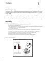
Ethernet 241™
Configuration Utility
User Manual
99009130 P
Thank You!
Congratulations on the purchase of your Ethernet 241™ device. RF IDeas hopes you enjoy using our
products as much as we enjoyed creating and developing them. Configuration is easy, so you will be
able to quickly take advantage of a more secure environment in your business, school, or
organization.
Visit www.RFIDeas.com and follow the Support a Learning Center link for more details about our
additional product lines.
We look forward to your comments and suggestions for our various product lines. We are always
discovering new applications and have several software developer’s licensing our technology so the
solution you are looking for may already be developed.
Please call our sales department if you have any questions or are interested in our OEM or
Independent Developer’s programs.
Thank you,
The RF IDeas Staff
Need Assistance?
2
Ph: 847.870.1723
Fx: 847.483.1129
E: [email protected]
[email protected]
END-USER LICENSE AGREEMENT
LICENSE AGREEMENT
End-User License Agreement for RF IDeas™ SOFTWARE and HARDWARE - RF IDeas’ pcProx®, Proximity Activated Readers, Software
Developer’s Kit, and Proximity Reader DLLs, and Protocol(s).
IMPORTANT-READ CAREFULLY: This End-User License Agreement (“EULA”) is a legal agreement between you (either an individual or a
single entity) and the manufacturer RF IDeas (“Manufacturer”) with which you acquired the RF IDeas software and hardware product(s)
identified above (“PRODUCT”). The PRODUCT includes the RF IDeas reader, computer software, the associated media, any printed
materials, and any “on line” or electronic documentation. By installing, copying or otherwise using the PRODUCT, you agree to be bound by
the terms of this EULA. The SOFTWARE PORTION OF THE PRODUCT includes the computer software, the associated media, any printed
materials, and any “on line” or electronic documentation. By installing, copying or otherwise using the PRODUCT, you agree to be bound by
the terms of this EULA. If you do not agree to the terms of this EULA, RF IDeas is unwilling to license the PRODUCT to you. In such event,
you may not use or copy the SOFTWARE PORTION OF THE PRODUCT, and you should promptly contact the vendor you obtained this
PRODUCT from for instructions on return of the unused product(s) for a refund.
The products described in this publication are intended for consumer applications. RF IDeas assumes no liability for the performance of
product. RF IDeas products are not suitable for use in life-support applications, biological hazard applications, nuclear control applications, or
radioactive areas. None of these products or components, software or hardware, are intended for applications that provide life support or any
critical function necessary for the support of protection of life, property or business interests. The user assumes responsibility for the use of
any of these products in any such application. RF IDeas shall not be liable for losses due to failure of any of these products, or components of
these products, beyond the RF IDeas commercial warranty, limited to the original purchase price.
SOFTWARE PRODUCT LICENSE The PRODUCT is protected by copyright laws and international copyright treaties, as well as other
intellectual property laws and treaties. The SOFTWARE PORTION OF THE PRODUCT is licensed, not sold.
1. GRANT OF LICENSE. This EULA grants you the following rights: *Software. You may install and use one copy of the SOFTWARE
PORTION OF THE PRODUCT on the COMPUTER. *Network Services. If the SOFTWARE PORTION OF THE PRODUCT includes
functionality that enables the COMPUTER to act as a network server, any number of computers or workstations may access or otherwise
utilize the basic network services of that server. The basic network services are more fully described in the printed materials accompanying
the SOFTWARE PORTION OF THE PRODUCT. *Storage/Network Use. You may also store or install a copy of the computer SOFTWARE
PORTION OF THE PRODUCT on the COMPUTER to allow your other computers to use the SOFTWARE PORTION OF THE PRODUCT
over an internal network, and distribute the SOFTWARE PORTION OF THE PRODUCT to your other computers over an internal network.
1.1 General License Grant RF IDeas grants to an individual, a personal, nonexclusive license to make and use copies of the SOFTWARE
PRODUCT for the sole purposes of designing, developing, and testing your software product(s) that are designed to operate in conjunction
with any RF IDeas designed proximity reader product. You may install copies of the SOFTWARE PRODUCT on an unlimited number of
computers provided that you are the only individual using the SOFTWARE PRODUCT. If you are an entity, RF IDeas grants the right to
designate one individual within your organization to have the sole right to use the SOFTWARE PRODUCT in the manner provided above.
1.2 Documentation. This EULA grants an individual, a personal, nonexclusive license to make and use an unlimited number of copies of any
documentation, provided that such copies shall be used only for personal purposes and are not to be republished or distributed (either in hard
copy or electronic form) beyond the user’s premises and with the following exception: you may use documentation identified in the
SOFTWARE PRODUCT as the file format specification for RF IDeas’ proximity readers solely in connection with your development of
software product(s) or an integrated work or product suite whose components include one or more general purpose software products.
1.3 Storage/Network Use. You may also store or install a copy of the SOFTWARE PRODUCT on a storage device, such as a network
server, used only to install or run the SOFTWARE PRODUCT on computers used by a licensed end user in accordance with Section 1.1. A
single license for the SOFTWARE PRODUCT may not be shared or used concurrently by other end users.
1.4 Sample Code. RF IDeas grants you the right to use and modify the source code version of those portions of the SOFTWARE
PRODUCT identified as “Samples in the SOFTWARE PRODUCT (“Sample Code”) for the sole purposes to design, develop, and test your
software product(s), and to reproduce and distribute the Sample Code, along with any modifications thereof, only in object code form.
2. DESCRIPTION OF OTHER RIGHTS AND LIMITATIONS.
*Limitations on Reverse Engineering, Decompilation and Disassembly. You may not reverse engineer, decompile, or disassemble the
PRODUCT, except and only to the extent that such activity is expressly permitted by applicable law notwithstanding this limitation
*You may not reproduce or otherwise emulate, in whole or in part, any form the protocol(s) defined within this PRODUCT for use
without a RF IDeas PRODUCT Redistributable Code. If you are authorized and choose to redistribute Sample Code (“Redistributables”) as
described in Section 1.4, you agree to: (a) distribute the Redistributables in object code only in conjunction with and as a part of a software
application product developed by you using the PRODUCT accompanying this EULA that adds significant and primary functionality to the
SOFTWARE PRODUCT (“Licensed Product”); (b) not use RF IDeas’ name, logo, or trademarks to market the Licensed Product; (c) include a
valid copyright notice on the Licensed Product; (d) indemnify, hold harmless, and defend RF IDeas from and against any claims or lawsuits,
including attorney’s fees, that arise or result from the use or distribution of the Licensed Product; (e) otherwise comply with the terms of this
EULA; and (g) agree that RF IDeas reserves all rights not expressly granted. You also agree not to permit further distribution of the
Redistributables by your end users except: (1) you may permit further redistribution of the Redistributables by your distributors to your
end-user customers if your distributors only distribute the Redistributables in conjunction with, and as part of, the Licensed Product and you
and your distributors comply with all other terms of this EULA; and (2) in the manner described in Section 1.4.
*Separation of Components. The PRODUCT is licensed as a single product. Its component parts may not be separated for use on more than
one computer.
*Single COMPUTER. The PRODUCT is licensed with the COMPUTER as a single integrated product. The PRODUCT may only be used with
the COMPUTER.
*Rental. You may not rent or lease the PRODUCT without permission from RF IDeas
*Software Transfer. You may permanently transfer all of your rights under this EULA only as part of a sale or transfer of the COMPUTER,
provided you retain no copies, you transfer all of the PRODUCT (including all component parts, the media and printed materials, any
upgrades, this EULA and, if applicable, the Certificate(s) of Authenticity), AND the recipient agrees to the terms of this EULA. If the
PRODUCT is an upgrade, any transfer must include all prior versions of the PRODUCT.
*Termination. Without prejudice to any other rights, RF IDeas may terminate this EULA if you fail to comply with the terms and conditions
of this EULA. In such event, you must destroy all copies of the SOFTWARE PORTION OF THE PRODUCT and all of its component parts.
3
3. UPGRADES. If the SOFTWARE PORTION OF THE PRODUCT is an upgrade from another product, whether from RF IDeas or another
supplier, you may use or transfer the PRODUCT only in conjunction with that upgraded product, unless you destroy the upgraded product. If
the SOFTWARE PORTION OF THE PRODUCT is an upgrade of a RF IDeas product, you now may use that upgraded product only in
accordance with this EULA. If the SOFTWARE PORTION OF THE PRODUCT is an upgrade of a component of a package of software
programs which you licensed as a single product, the SOFTWARE PORTION OF THE PRODUCT may be used and transferred only as part
of that single product package and may not be separated for use on more than one computer.
4. OEM COPYRIGHT. All title and copyrights in and to the PRODUCT (including but not limited to images, photographs, animations, video,
audio, music, text and “applets,” incorporated into the PRODUCT), the accompanying printed materials, and any copies of the SOFTWARE
PORTION OF THE PRODUCT, are owned by RF IDeas or its suppliers. The PRODUCT and SOFTWARE PORTION OF THE PRODUCT is
protected by copyright laws and international treaty provisions. You may not copy the printed materials accompanying the PRODUCT.
5. DUAL-MEDIA SOFTWARE. You may receive the SOFTWARE PORTION OF THE PRODUCT in more than one medium. Regardless of
the type or size of medium you receive, you may use only one medium that is appropriate for your single computer. You may not use or install
the other medium on another computer. You may not loan, rent, lease, or otherwise transfer the other medium to another user, except as part
of the permanent transfer (as provided above) of the SOFTWARE PORTION OF THE PRODUCT.
6. OEM PRODUCT SUPPORT. Product support for the product is not provided by RF IDeas or its subsidiaries. For product support, please
refer to the OEM supplies support number provided in the documentation. Should you have any questions concerning the EULA, or if you
desire to contact OEM for any other reason, please refer to the address provided in the documentation provided.
FOR THE LIMITED WARRANTIES AND SPECIAL PROVISIONS PERTAINING TO YOUR PARTICULAR JURISDICTION, PLEASE REFER
TO YOUR WARRANTY BOOKLET INCLUDED WITH THIS PACKAGE OR PROVIDED WITH THE SOFTWARE PRODUCT PRINTED
MATERIALS.
Limited Warranty: RF IDeas warrants to the original buyer of this product, that the hardware and related disk(s) are free of defects in
material and workmanship for a period of one year from date of purchase from RF IDeas or from an authorized RF IDeas dealer. Should the
RF IDeas products fail to be in good working order at any time during the one-year period, RF IDeas will, at its option, repair or replace the
product at no additional charge, provided that the product has not been abused, misused, repaired or modified. This warranty shall be limited
to repair or replacement and in no event shall RF IDeas be liable for any loss of profit or any commercial or other damages,
including but not limited to special, incidental, consequential or other similar claims.
No dealer, distributor, company, or person has been authorized to change or add to the terms of this agreement, and RF IDeas will not be
bound by any representation to the contrary. RF IDeas SPECIFICALLY DISCLAIMS ALL OTHER WARRANTIES, EXPRESSED OR
IMPLIED, INCLUDING BUT NOT LIMITED TO IMPLIED WARRANTIES OF MERCHANTABILITY AND FITNESS OF PURPOSE. Since some
states do not allow such exclusion of limitation of incidental or consequential damages for consumer products, check the statute of
the state in which your business resides. This warranty gives you the specific legal rights in addition to any rights that you have under the
laws of the state in which your business resides or operates.
Returns: RF IDeas products which require Limited Warranty service during the warranty period shall be delivered to the nearest authorized
dealer or sent directly to RF IDeas at the address below with proof of purchase and a Return Materials Authorization (RMA) Number provided
by RF IDeas Technical Support Dept. Replacement parts or complete boards become the property of RF IDeas If the returned board or unit
is sent by mail, the purchaser agrees to pre-pay the shipping charges and insure the board or unit or assume the risk of loss or damage which
may occur in transit. The purchaser is expected to employ a container equivalent to the original packaging.
Copyright: Copyright by RF IDeas 2011. All rights reserved. Reproduction or distribution of this document in whole or in part or in any form
is prohibited without express written permission from RF IDeas.
Trademarks: All RF IDeas products are trademarks of RF IDeas. All other product names or names are trademarks or registered
trademarks of their respective holders.
Disclaimer: This Reference Guide is printed in the U.S.A. Any resemblance mentioned in the Reference Guide to persons living or dead, or
to actual corporations or products is purely coincidental. RF IDeas believes that the information contained in this manual is correct.
However, RF IDeas does not assume any responsibility for the accuracy of the content of this User Manual, nor for any patent infringements
or other rights of third parties. RF IDeas reserves the right to make any modifications in either product or the manual without giving prior
written notification.
FCC Compliance Statement
FCC ID: M9MPCPROXHUSB100 (HID USB model)
FCC ID: M9MPCPROXM101 (Indala model)
FCC ID: M9MRDR6X8X (Kantech, Indala, Casi-Rusco)
FCC ID: M9MPCPROXC101 (Casi-Rusco model)
FCC ID: M9MRFID1856I100 (MIFARE/iCLASS models)
FCC ID: M9MRDR7081 (iCLASS Module based)
FCC ID: M9MRDR7581 (iCLASS MIFARE and Other 13.56MHz) FCC ID: M9MRDR7081AKE (iCLASS MIFARE and Other 13.56MHz) FCC ID: M9MRDR8XX8U (Plus combo model)
FCC ID: M9MRDR8058X (Multi-protocol Combo model)
FCC ID: M9M758XCCL (MIFARE and Contact model)
FCC ID: M9MRDR80081 (Plus SIO Combo Model)
FCC ID: M9MBUPCPROXH100 (HID RS-232 model)
FCC ID: M9MBUPCPROXA100 (AWID)
FCC ID: M9MPCPROXP100 (Pyramid)
FCC ID: M9MRDR7P71 (FIPS 201 13.56MHz)
FCC ID: M9MRDR7L81 (Legic 13.56MHz)
FCC ID: M9MRDR7580 (iCLASS MIFARE and Other 13.56MHz)
FCC ID: M9MRDR7081AKF (iCLASS MIFARE and Other 13.56MHz)
FCC ID: M9MRDR75DX (iCLASS MIFARE and Other 13.56MHz)
FCC ID: M9MRDR758X (iCLASS MIFARE and Other 13.56 MHz)
FCC ID: M9M8058XCCL (Multi-protocol and Contact model)
FCC ID: M9M7580CCL (MIFARE and Contact model)
“Pursuant to FCC 15.21 of the FCC rules, changes not expressly approved by RF IDeas might cause harmful interference and void the FCC
authorization to operate this product.
Note: This device complies with Part 15 of the FCC Rules and Industry Canada license-exempt RSS standard(s). Operation is subject to
the following two conditions: (1) This device may not cause harmful interference, and (2) this device must accept any interference received,
including interference that may cause undesired operation. This product complies with FCC OET Bulletin 65 radiation exposure limits set forth
for an uncontrolled environment.
The reader may not recognize value cards in the presence of high RF fields. If the current reading is erratic, the user shall take the following
step: Move the equipment from any known transmitters nearby. For more information contact Tech Support at 866.439.4884.
4
Contents
5
2
Thank You!
6
6
6
Chapter 1: The Basics
Product Description
Device Features
7
7
7
7
7
Chapter 2: Operation
Switch Operation
Serial Port Operation
Serial Tunnel Operation
Telnet Operation
8
8
Chapter 3: Configuration
Operation Modes
12 12 12 13 13 13 13 13 14 14 16 Chapter 4: Commands
Echo
Exit
Factory_Reset
Password
Reboot
Set
Show
Version
Examples
Command Response Messages
17 17 17 17 Chapter 5: Additional Device Features
LED Indicators
Button
Discovery Server
20 Index
1
The Basics
Overview
Product Description
The Ethernet 241™ is a 2-port Ethernet switch that includes a serial port. The Ethernet 241 is meant
to connect between a network printer and its network with the serial port attaching to an RF IDeas
pcProx® reader.
The Ethernet 241 will forward Ethernet packets between its 2 ports and provide a TCP tunnel to the
serial port. The tunnel provides the means for badge reader data to be read by a remote computer,
which will use badge information to control dispatching jobs to the printer.
Device Features
The Ethernet 241 features include:
• IP address may be statically assigned or obtained via DHCP
• 2-port Ethernet software switch
• Each Ethernet port may be configured to link modes: auto-negotiate, 100 Mbps full-duplex, 10 Mbps full-duplex, or 10 Mbps half-duplex
• TCP tunnel to serial port
• Discovery protocol provides means for finding all Ethernet 241 devices on a network
• Command line interface via serial port or Telnet for management and configuration
• Dual-purpose button to invoke the command line or to reset configuration.
• Automatic backup copies of configuration data and software
• Client (push data to a server asynchronously) or Server (polled) modes.
Figure 1 - Connection Setup
Ethernet 241 Connection
Connect reader to Ethernet 241
device via RS-232 interface
RJ45
Connect Ethernet 241 to existing
network connection, through the
device’s network connection port.
6
Connect Ethernet 241 device to
the RJ45 printer port
Operation
2
Device Operations
Switch Operation
The Ethernet 241 will inspect packets received at the network-facing port. Based on the destination
IP address and TCP or UDP port number, the Ethernet 241 will decide if a packet is to be forwarded
to the printer or if it is to be passed to the Ethernet 241’s internal network stack for processing. The
Ethernet 241 will process ARP requests for its IP address, UDP packets directed at the Discovery port,
DHCP packets, TCP packets directed at the tunnel port, and TCP packets directed at the Telnet port.
In some cases such as ARP, a packet will be passed to the printer port and also copied to the Ethernet
241 network stack.
Serial Port Operation
By default the serial port is available for tunneling between the badge reader and a TCP connection.
When the button is pressed, the serial port is placed into command line mode, forcing a tunnel
connection to close if one is active. If a valid command is not entered within 30 seconds after the
command line is activated on the serial port, the command line should be closed, once again making
the serial available for tunneling.
Serial Tunnel Operation
A serial tunnel will be established when a remote computer initiates a TCP connection to the
Ethernet 241’s tunnel port. When the tunnel is active, the Ethernet 241 will forward data between the
serial port and the remote computer.
If the button on the Ethernet 241 is pressed to enable the command on the serial port and there is a
serial tunnel active, the tunnel will be forced closed and the command prompt will be presented on
the serial interface.
Telnet Operation
The Ethernet 241 provides a Telnet server. When a remote client connects to the server, it will provide
a command line interface, through which configuration settings may be inspected and changed. An
optional password may be applied to the Telnet interface.
When the Telnet connection is established, the server will first prompt whether or not echoing of
characters is to be enabled:
RF IDeas Ethernet 241, enable echo [Y|N]>
Once that prompt is answered, if there is a password set, the next prompt will be for the password:
Password>
Otherwise the command prompt will be presented.
7
Configuration
3
Device Configuration
The behavior of the Ethernet 241 is controlled by several configurable parameters that may be viewed
and changed via the command line (see the ‘set’ and ‘show’ commands). Each parameter is
referenced by name. Parameter names, valid values, and factory default values are listed in Table 2
(pg. 10-11). Changes to parameters will take effect on the next reboot of the Ethernet 241.
Parameters are stored in serial flash. A backup copy of the most recent valid set of parameters is
kept in a separate area. In case the primary parameter store becomes corrupted, the contents of the
backup will be copied over the primary storage area.
If DHCP is not active on your network, programming can be achieved by connecting a Serial null
modem cable to the RS-232 port on the Ethernet 241 Device.
Note: Serial null modem cables are available as an accessory from RF IDeas or installer supplied.
Available cable type: DB9 Female to DB9 Female Null Modem Cable
Operation Modes
The 241 will operate in one of two user selectable modes: client and server.
Server Configuration Mode
In server configuration, card data must be polled asynchronously by a host.
Client Configuration Mode
In client mode, when card data is received from the reader, the 241 connects to a specified host
and sends a URL with user specified information that can include the card data, the reader LUID,
the 241 MAC and IP address.
serv_client
= on or off
Note: on is the default
After power-on, network discovery and network configuration, the 241 may request a reader
configuration string for a user defined server port at a user-defined URL or IP address. If an IP
address is specified and not the default, it will be used, otherwise the URL will be used.
The Query String is the part of the URL that contains data to be passed to a web application. The
response time from receiving the card data string from the reader to the server connection and data transmission will be less than 50ms.
When a server data URL is specified and a card has been read by the reader, the 241 will format a URL
string appending the user specified Server Data URL and Server Data Str with a parameter string
that may contain the card id, the 241 MAC address, 241 IP address, the reader LUID and/or 16-bit
sequence number.
8
All URL parameters will expand the strings $1 through $7 stripping CR and/or LF characters.
Parameters and expansion rules are as follows:
Table 1 - URL Parameters
URL Parameter
Expands to
$1
The card ID from the reader from 1 to 32 hexadecimal characters in length (leading
spaces stripped)
$2
The 241 Network port MAC address as 12 lower case hexadecimal digits
$3
The 4 digit hex LUID as read from the reader by the 241 after power-up and initialization
$4
A 16-bit sequence number initialized to 0 on start-up and incremented on each
successful server connect
$5
The IP Address of the 241
$6
The attached device port MAC address as 12 lower case hexadecimal digits
$7
The IP Address of the device attached to the device port
Parameter Example:
data_serv_url = http://www.serverName.com
data_str = /url/path/?cardid=$1&mac=$2&luid=$3&seq=$4&ip=$5&devmac=$6&devip=$7
http://www.serverName.com/url/path/?cardid=$1&mac=$2&luid=$3&seq=$4&ip=$5&devmac=$6&de
vip=$7
In response to the 241 card data written to the server, the server will acknowledge receipt of the card
data. The reply may include lines of text separated by CR and/or LF’s within special tags that begin
with <RFIDeasACP> and end with </RFIDeasACP>.
The 241 must be able to receive a 1024 character reply string.
All lines of text starting with “rfid:” will be sent to the reader. The 241 will wait for the serial prompt
or delay for 100ms prior to sending the next line.
The command sleep (uint16_t ms) will inform the 241 to delay by ms milliseconds before sending the
next command to the reader.
The 241 will strip leading and trailing white space from the command.
Valid reader commands may occur inside html comments.
Reader Command Example:
<html>
<body>OK
<!-
<RFIDeasACP>
rfid:beep.now=2
sleep(500)
</RFIDeasACP>
-->
</body>
9
Chapter 3
Configuration
</html>
init_serv_addr = 0.0.0.0
init_serv_url = http://www.rfideas241.com
init_serv_port = 80
init_str
= /demo/init/init.php?csn=$1&mac=$2&luid=$3&seq=$4&ip=$5
init_retry_count = 10
init_retry_sleep = 2
init_short_beep = 5
init_long_beep = 2
data_serv_addr = 0.0.0.0
data_serv_url = http://www.rfideas241.com
data_serv_port = 80
data_str
= /demo/data/put.php?csn=$1&mac=$2&luid=$3&seq=$4&ip=$5
data_retry_count = 10
data_retry_sleep = 2
data_short_beep = 5
data_long_beep = 2
Table 2 - Configuration Parameters
Parameter Name
10
Default
Parameter Range
Description
baud_rate
9600
9600, 57600
Serial port baud rate (bps)
char_size
8
8
Character width in bits
parity
None
None
Parity
flow_control
None
None
Flow Control
telnet_pot
23
0 through 65535 (inclusive)
Network to 241 Telnet port #
tunnel_port
2000
0 through 65535 (inclusive)
Network to Reader port #
ip_addr_mode
dhcp
dhcp, static
Address Mode
ip_addr
192.168.1.2
0.0.0.0 through
255.255.255.255 (inclusive)
Static IP Address
ip_mask
255.255.255.0
0.0.0.0 through
255.255.255.255 (inclusive)
Static IP Mask
gw_addr
0.0.0.0
0.0.0.0 through
255.255.255.255 (inclusive)
Static Gateway Address
dns1_addr
0.0.0.0
0.0.0.0 through
255.255.255.255 (inclusive)
Static DNS address
dns2_addr
0.0.0.0
0.0.0.0 through
255.255.255.255 (inclusive)
Static DNS address
eth0_mode
Auto-negotiate
10 Half Dup, 10Full Dup., 100 Full Ethernet (Network) Mode
Dup, Auto
eth1_mode
Auto-negotiate
10 Half Dup, 10Full Dup., 100 Full Ethernet (Device) Mode
Dup, Auto
location
“”
40 ASCII Characters
Location string
serv_client
on
on, off
on, card data sent to server
off, card data requested by client
ssl_enabled
No
No ( default), Yes
SSL state
ssl_port
443 (HTTPS)
0 through 65355 (inclusive)
SSL port number
ssh_enabled
No
No ( default), Yes
SSH state
Chapter 3
Configuration
Parameter Name
11
Default
Parameter Range
Description
ssh_port
22 (SSH)
0 through 65355 (inclusive)
SSH port number
init_serv_url
“”
200 characters
URL of Reader initialization server
init_serv_port
80 (HTTP)
0 through 65535 (inclusive)
Reader initialization Server Port #
init_serv_str
“”
200 characters
Reader initialization String
init_retry_count
10
0 through 255 (inclusive)
Retry limit if connection attempts fail
init_retry_sleep
2
1 through 255 (inclusive)
Interval between retries
init_long_beep
2
1-2 (beep.now = 101 | 102)
Long beeps if server init connect fails
init_short_beep
5
1-5 (beep.now = 1 | 2 | 3 | 4 | 5)
Short beeps if server init connect fails
data_serv_url
“”
200 characters (inclusive)
URL with parameter string
data_serv_port
80 (HTTP)
0 through 65535 (inclusive)
Reader Data Server Port #
data_serv_str
“”
200 characters
Reader Data String
data_retry_count
10
0 through 255 (inclusive)
Retry limit if connection attempts fail
data_retry_sleep
2
1 through 255 (inclusive)
Interval between retries
data_long_beep
2
1-2 (beep.now = 101 | 102)
Long beeps if server data connect fails
data_short_beep
5
1-5 (beep.now = 1 | 2 | 3 | 4 | 5)
Short beeps if server data connect fails
web_serv_port
80
0-65535
The port number of the 241 web server
password
“”
20 characters
The telnet/tunnel/web password
Chapter 3
Configuration
Commands
4
Command Line
The command line is available to the serial port and via Telnet. It is designed to accommodate either
human interaction or automated (scripted) operation. Character echo may optionally be disabled to
support machine-to-machine communication.
RF IDeas{}>
Inside the curly braces may be optional flag characters that indicate current conditions. The letter ‘T’
would indicate that there is an active serial tunnel.
After a command is entered and processed, a response line will be printed and a new prompt will be
presented:
nnn:TTT
RF IDeas{}>
The “nnn” preceding the colon will be a 3-digit response code. The “TTT” following the colon will be
a mnemonic string. For example, the response line for a command that was completed successfully
would be:
000:OK
Certain commands (‘exit’, and ‘reboot’) will print the response string before the command is
processed. This is done because the command will close or alter the command line session.
Command lines are terminated by a newline (return key) character.
Echo
Syntax: echo on|off
This command provides control over whether or not characters will be echoed as they are entered at
the command prompt. Normally, when a human is using the console, echo will be enabled. If an
automated script is used to communicate with the command prompt, echo can be disabled.
Exit
Syntax: exit
This command will terminate the command line. The response message will be output before the exit
operation is performed.
If the console was being accessed via the serial port, this command will cause the serial port to be
12
closed and tunneling will again be available to that port.
Exit -- (Continued)
If the console was being accessed via the Telnet server, this command will cause the Telnet TCP
connection to be closed.
Factory_reset
Syntax: factory_reset
This command will reset all parameters to their factory default values per Table 2 and the Telnet
password will be cleared.
Parameters may also be reset by holding the button closed for 5 seconds during power up.
Note: the system LED will turn red and then green, at which point the button can then be released
Password
Syntax: password
This command will set the Telnet password. This command will prompt twice for the password to be
echoed. The password will not be displayed as it is typed. If the password is entered the same way
twice, the change will be stored. Entering an empty line at the two prompts will clear the password.
Reboot
Syntax: reboot
This command causes the Ethernet 241 to reboot.
Upon receipt of this command, the Ethernet 241 will output the response message “001:REBOOT”,
wait 250 milliseconds and then perform the reboot operation. If this command is sent via the Telnet
interface, the Telnet connection will be closed before the reboot is performed.
Set
Syntax: set <name> <value>
This command will change the value of a parameter where ‘name’ identifies the parameter to be
changed and ‘value’ must be a valid value for that parameter as given in Table 2.
Changes to parameters will take effect on the next reboot of the Ethernet 241.
Show
Syntax: show <name>|all
This command will display the value for a specified parameter or if the “all” keyword is given it will
13
Chapter 4
Commands
display a list of parameter names and the value for each.
Version
Syntax: version
This command causes the version of Ethernet 241 software to be displayed. The version number will
of the form x.yy where “x” is the major version and “yy” is the minor version (00-99).
Examples
The Ethernet 241 (Ethernet 241 for RF IDeas serial reader) accepts Telnet connects on two ports:
23 and 2000.
• Port 23 allows you to setup the Ethernet 241 operation.
• Port 2000 provides a tunnel port that passes serial data thru to the RF IDeas pcProx
Plus serial reader. Port 2000 will not accept connections while 23 is active so before
disconnecting from port 23 make sure you type ‘exit’ to close the shell.
For this example, Ethernet 241 has an IP address: 10.10.10.87. Note, yours may be different.
Below we will turn off the echo in the shell.
Note: BOLD Signifies what is sent/typed
Commands Example 1:
Set up for use with echoes disabled and connect the 241.
1. Telnet into 10.10.10.87 23
Open a CMD.exe shell
Telnet 10.10.10.87 23
RFIDeas 241, enable echo [Y|N]>Y
2. RF IDeas{}>echo off
RF IDeas{}>exit
3. Connect AK5 reader to DB-9
4. Telnet into port 2000
Telnet 10.10.10.87 2000
5. Since Microsoft Telnet echos too, turn off echo on Reader with rfid:cmd.echo=0
Type: rfid:cmd.echo=0 which appears as…
RF IDeas>rrffiidd::ccmmdd..eecchhoo==00
14
Chapter 4
Commands
Commands Example 2:
Show all card technologies available.
RF IDeas>rfid:cfg.card.list
0x0000 --- OFF --0x7F31 Advant CSN (Legic)
0xFA02 Awid : RDR-698x Compatible
0xF602 Cardax UID : RDR-6C8x Compatible
0xFC02 CASI-RUSCO (GE Security, UTC) : RDR-628x Compatible
0xE912 CDVI
0xF401 Deister UID
0x7F01 DESFire CSN
0xFB11 DIGITAG
0xF101 Dimpna UID
0xFB01 EM 410x : RDR-6E8x Compatible
0xFB02 EM 410x Alternate
0x7E31 etag CSN (Secura Key)
0xEA22 Farpointe Data (Pyramid) PSC-1 26 Bit : RDR-647x Compatible
0xEA21 Farpointe Data (Pyramid) UID
0xF502 GProx-II UID : RDR-6G8x Compatible
0x7D01 HID iCLASS CSN
*0xEF04 HID Prox : RDR-608x Compatible
0xEF01 HID Prox UID
0xF302 HiTag 1 & S : RDR-6H8x Compatible
0xF304 HiTag 1 & S Alternate
0xF201 HiTag 2 : RDR-6H8x Compatible
0xF204 HiTag 2 Alternate
0x7E01 I-Code CSN (Philips, NXP)
0x7F11 I-tag CSN (IBM)
0xFD02 Indala ASP 26 bit (Motorola) : RDR-638x Compatible
0xFD01 Indala ASP UID (Motorola)
0xFD04 Indala ASP Custom : Please contact RF IDeas sales
0xED02 Indala ASP+ UID (Motorola)
0xED05 Indala ASP+ Custom : Please contact RF IDeas sales
0xFD05 Indala ECR Custom : Please contact RF IDeas sales
0xF902 ioProx (Kantech) : RDR-678x Compatible
0x7F21 ISO 14443A CSN
0x7E21 ISO 15693 CSN
0xEA01 Keri NXT UID
0xEA02 Keri PSC-1 26 Bit
0xF802 Keri UID : RDR-6K8x Compatible
0x7F41 MiFare CSN (Philips, NXP)
0x7F51 MiFare Ultralight CSN (Philips, NXP)
0x7E11 my-d CSN (Infineon)
0xF722 NexKey, Quadrakey, KeyMate, 2Smart Key (Honeywell)
0xF712 Nexwatch (Honeywell) : RDR 6N8x Compatible
0xE902 Paradox
0xEA12 Pyramid (Farpointe Data) PSC-1 26 Bit
0xEA11 Pyramid (Farpointe Data) UID
0xEB02 Radio Key (Secura Key -02) RKCx-02 : RDR-6Z8x Compatible
0x6F01 RDR-758x Equivalent
0xF004 ReadyKey Pro UID : RDR-6R8x Compatible
0xFB21 Rosslare
0xF612 Russwin UID
0xEC01 Secura Key -01 RKCx-01
0x7E41 Tag-It CSN (Texas Instruments)
RF IDeas>
15
Chapter 4
Commands
Commands Example 3:
Here we show you how to set two different card technologies in the pcProx Plus reader. To set
configuration #1 to Paradox and configuration #2 to Tagit
RF IDeas>rfid:cfg=1
RF IDeas>rfid:cfg.card.type=0xe902
RF IDeas>rfid:cfg=2
RF IDeas>rfid:cfg.card.type=0x7E41
RF IDeas>rfid:cfg.write
{OK}
RF IDeas>
Command Response Messages
Once a command is processed, the command processor will print a status reply, a carriage-return
and newline and a new prompt. The status reply will be a 3-digit status code followed by a colon and
a mnemonic for the status. The number is provided so that an automated script may easily parse the
result of a command. The mnemonic is provided for human interaction.
Response codes in the range 000-099 indicate success with possible additional conditions such as
rebooting. Response codes in the range 100-999 indicate error conditions. Table 2 lists the defined
status messages.
Table 3: Status Messages
Status Message
16
Meaning
000: OK
Command processed successfully
001: REBOOT
The device is rebooting. The host system must wait several seconds before attempting to
communicate again with the device.
002: CLOSED
The Telnet session has been closed. There will not be a command prompt after this
message.
100:CMD-BAD
Command not understood
101: PARAM-BAD
The parameter name for the set / show commands does not match one accepted by this
device.
102: PARAM-VAL
The value specified for the selected parameter is out of range.
106: SYS-ERR
An internal error occurred while processing the command.
107: TIMEOUT
No command was typed with the 30 second time limit.
Chapter 4
Commands
Additional Device Features
5
LED indicators
The Ethernet 241 provides the following LED indicators.
• System Status. This is a bi-color (Red/Green) LED that indicates the current status of the
Ethernet 241. The LED will be green when the Ethernet 241 is operating normally and red if
there is an error condition.
• Ethernet link/activity. Each Ethernet port has a green LED that indicates the presence of
Ethernet link, the speed of the link and whether there is activity:
OFF = no link
ON = link present
The LED will flash in the presence of activity or remain solid in the absence of activity.
• Serial RX/TX. This is a green/yellow LED that will flash green when data is being received
from the badge reader and flash yellow when data is being transmitted to the badge reader.
Button
The Ethernet 241 has a recessed button that provides two functions:
• When the button is pressed momentarily and released the command line will be presented
at the serial port. If there was a tunnel session in progress at the time, it will be forced closed.
If a valid command is not entered at the command prompt within 30 seconds, the command
prompt will be canceled and the serial port will again be available for tunneling.
• When the button is held for 5 seconds during power up (Note: the system LED will turn red
and then green, at which point the button can then be released), parameters will be reset to
their factory values and the Ethernet 241 will reboot.
Discovery
The Ethernet 241 provides a Discovery server. This is a process that listens at UDP port 11000 for a
Discovery Request message. When a message of this format is received, the server will send back to
the requesting IP address and port number a response message that identifies the Ethernet 241 and
provides information about its current state.
A host system is required having software that will broadcast the Discovery Request message and
collect, interpret and display information about the responding Ethernet 241 devices on the network.
Network – Discovery
The 241 will listen on a UDP socket at the Discovery port, 11000, for a Discovery Request packet.
The 241 will respond with a Discovery Reply packet identifying itself to a host system on the
network.
17
The Discovery Request message will conform to the following:
Table 4: Discovery Request
Byte Offset
Length
Description
0
8
'RFIDDISC'
8
1
1 (Message Type 1= Discovery Request)
9
1
0 (Reserved – Future)
The Discovery Response message is sent in response to the Discovery Request message and will
conform to the following format:
Table 5: Discovery Response
18
Chapter 5
Byte Offset
Length
Description
0
8
'RFIDDISC'
8
1
2 (Message Type 2= Discovery Reply)
9
1
1 (Discovery Response Version v2.41 )
10
4
0xF4 0xF0 0xF2 0xF0
14
14
'-RFIDeas/Wedge '
28
1
0x0
29
6
Network port MAC address
35
1
Pad (0)
36
4
Network port IP Address
40
4
Net mask
44
4
Gateway Address
48
40
88
4
Device Status bit mask (see see REQ010.2.3)
92
4
Telnet connection IP address
Null terminated location string
96
2
Tunnel connection remote port
98
4
Tunnel Connection IP address
102
2
Tunnel connection remote port
104
6
Device port MAC address
110
4
Device IP address
114
14
Reserved (0)
Additional Device Features
The Discovery Response Device Status bit mask will conform to the following format:
Table 6: Discovery Response Device Status
Bit Offset
19
Chapter 5
Description
1:0
Network Port Status
0=link down
01=link up 10 Mbps half duplex
10=link up 10 Mbps full duplex
11=link up 100 Mbps full duplex
3:2
Printer port status
0 = link down
01 = link up 10 Mbps half duplex
10 = link up 10 Mbps full duplex
11 = link up 100 Mbps full duplex
4
Tunnel status
0 = idle
1 = active
5
Telnet status
0 = idle
1 = active
6
Reserved (0)
7
Reserved (0)
11:8
Software status
0 = normal operation
1 = corrupted configuration
2-15 = Reserved
31:12
Reserved (0)
Additional Device Features
Index
Index
C
P
Card Technologies
15
Client Configuration Mode
Command Line
12
Configuration Parameters
(see Parameters)
Paradox
16
Parameters
8-11
pcProx Plus
14, 16
8
S
Serial RX/TX
17
Server Configuration Mode
Status Messages
14
System Status
17
D
DHCP
6-8
Discovery Protocol
6-8, 17-18
E
T
Ethernet Link/Activity
17
Tagit
TCP
Telnet
L
LED
LUID
17
8-9
U
UDP
7, 17
URL Parameters
N
Network Discovery
20
16
6-7, 13
6-7, 10-14, 16
17
9
8
RF IDeas Inc.
© 2012 RF IDeas. All rights reserved.
Specifications subject to change without notice.
Windows, Macintosh, Solaris, Sun Ray and Linux are trademarks of their respective companies.
All other trademarks, service marks and product or service names are property of their respective owners.
Mention of third-party products is for informational purposes only and constitutes neither an endorsement nor a
recommendation. RF IDeas assumes no responsibility with regard to the performance or use of these products.
All understandings, agreements, or warranties, if any, take place directly between the vendors and the prospective users.
Please feel free to call, e-mail or visit our web site for a full list of applications, products, configuration options, supported
cards and form factor specifications. Our web site includes application videos, support materials, case studies and
detailed information about our product line.
Every effort has been made to ensure that the information in this manual is accurate. RF IDeas is not responsible for printing or
clerical errors.