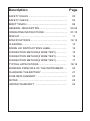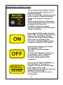
1
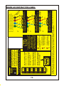
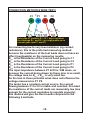
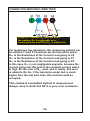
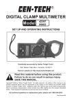
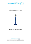
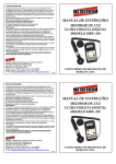
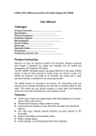
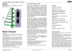
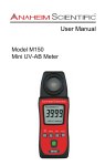
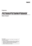
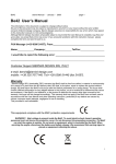
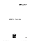
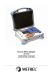
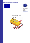
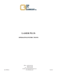
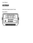
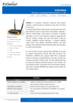
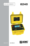
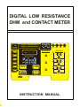
E
S
T
N
R
G
O
IE
P
S
DIGITAL LOW RESISTANCE
OHM and CONTACT METER
15VAC
or
17VDC
BATTERY
CHARGER
DIGITAL LOW RESISTANCE
OHM and CONTACT METER
MICROPROCESSOR CONTROLLED
RC
C1 + P1
P2
C2
AC
DC
100mA
2000mW
OFF
MAX
MIN
P1
mV
kMW
C1
P1
Start/Stop
P2
C2
I
ON
TEST
C2
3T
C1
P1
+ V
2T
SCROLL
RANGE
P2
+ V
VDC / 4T
3T / 2T
10mA
200.0W
C2
I
Hz
kA
ms
P2
+ V
4T
MANUAL RANGING
HOLD
CONNECTIONS
C1
RP
1A
20.00mW
RANGE
CF
MEASUREMENT
ICCS OFF
100mA
20.00W
FUSE
PF
CROWBAR FUSES
1A
2.000mW
1A
200.0mW
FUSE
I
INSTRUCTION MANUAL
Description
Page
SAFETY RULES ......................................................
03
SAFETY CHECK .....................................................
04
DON'T TOUCH ........................................................
04
GENERAL DESCRIPTION ......................................
05-06
OPERATING INSTRUCTIONS ................................
07-10
DISPLAY ..................................................................
11
SPECIFICATIONS ...................................................
12-13
CLEANING ..............................................................
13
INSIDE LID INSTRUCTIONS LABEL ......................
14
CONNECTION METHOD(4 WIRE TEST) ..............
15
CONNECTION METHOD(3 WIRE TEST) ...............
16
CONNECTION METHOD(2 WIRE TEST) ...............
17
TYPICAL APPLICATIONS .......................................
18-19
WORKING PRINCIPLE OF THE INSTRUMENT......
20
CHARGING THE BATTERY ....................................
21
FUSE REPLACEMENT ...........................................
22
NOTES ....................................................................
23
LIMITED WARRANTY .............................................
24
SAFETY RULES
CAUTION
RISK OF ELECTRIC
SHOCK
This tester has been designed with your safety in mind. However, no
design can completely protect against incorrect use. Electrical
circuits can be dangerous and/or lethal when lack of caution or poor
safety practices are used.
Do not carry out field measurements on either the power system
grounding or anything connected to it, without ensuring the contact or
circuit under test is fully isolated.
Take all the necessary precautions. Do not exceed the limits of this
instrument. The circuit to be tested must be de-energised and isolated
before connections are made to it.
Do not use test leads, probes or crocodiles/aligators clips that are
dirty, damaged or have broken or cracked insulation. Such
accessories should be removed and repaired Immediately.
Always disconnect the test leads before replacing any fuse. Always
replace the fuse with the type specified and ensure that they are
correctly fitted.
Double check your settings and leads connections before measuring.
Make a sketch to ensure proper operation and the principle of
measurement is correct and well understood.
Do not touch any exposed wiring, connections or other "live" parts of
an electrical circuit. If in doubt, check the circuit for no voltage first
before testing it.
Disconnect the tester from any external circuit when charging the
battery.
CAUTION
READ THE MANUAL
Follow the instructions in the Manual for every measurement. Read
and understand the general instructions before attempting to use this
tester.
-3-
SAFETY CHECK
Before using the tester check the condition of the battery. This is
done by switching the tester ON.
If the BAT LOW symbol appears the battery needs charging.
When charging the battery, changing a fuse, or removing the cover to
access the internal circuitry, always disconnect the test leads.
When replacing the fuse use only the type specified, and insert
correctly in the fuse holder.
Double check the settings, and lead connections before making
measurements.
DON'T TOUCH
Don't touch exposed wiring, connections or other "Live"
parts of an electrical circuit. If in doubt, check the circuit
first for voltage before touching or connecting to it.
Do not use cracked of broken test leads.
THIS INSTRUMENT SHOULD ONLY BE USED BY A
COMPETENT, SUITABLY TRAINED PERSON.
REMEMBER
SAFETY IS NO ACCIDENT
CAUTION RISK OF ELECTRIC SHOCK
CAUTION READ THE MANUAL
-4-
GENERAL DESCRIPTION
The Digital Low Resistance Ohm and Contact Meter is a battery
(rechargeable) operated instrument which supplies a constant current
to the circuit under test, with which is stable for accurate
measurements of very low resistance (down a micro ohm) over a wide
range of values.
Resolution on the lowest range is 1µohm and on the highest range,
100 milli-ohm.
The meter has 6 measuring ranges, from 2000 micro-ohm to 200.0
ohms.
Measurements are displayed on a large 3½ digit custom liquid crystal
display.
This instrument is powered from it's internal rechargeable battery.
It has a regulated DC constant current source with current of 10mA
100mA and 1A.
When recharging the battery, the instrument is disconnected from the
battery. Measurements can only be made while not charging.
The instrument supplies the current to the resistance being measured
through the C1 and C2 terminals (C1 being +, C2 being -).
The voltage drop across the resistance under test is measured by the
potential terminals P1 and P2 (P1 being +, P2 being -).
Should the current regulation fall out, the RC LED will indicate, that the
resistance in the current circuit is too high. (Lowering the current by
selecting a higher resistance range can solve the regulation.)
Should the RP LED light up, it mean that the voltage measured on the
resistance is too high, and therefore over-range.
(Lowering the current by selecting a higher resistance range can solve
the over voltage on RP.)
The resistance can only be measured precisely when the RP and RC
LEDs are not lit. If any of these LEDs lights up, then the measurement
will be inaccurate.
-5-
The ICCS LED indicates the Constant Current Source is OFF. When this
LED lights up, it means that the current injection has been switched
OFF (eg could be over-temperature).
The meter has a built-in custom 3½ digit liquid crystal display which
can be viewed in most lighting conditions.
This display indicates the conditions (Hold, m, buzzer, polarity
condition of load, + or -, automatic decimal point change with range
selection).
The ranges are selected by the "SCROLL / RANGE" push button.
A test is initiated by pressing the TEST/STOP push-button.
The instrument takes measurements for 10 seconds if the TEST/STOP
push-button is depressed for less than 3 seconds (EnerSave mode).
If the TEST/STOP push button is depressed for more than 3 seconds,
the test will carry on for 60 seconds.
The tester switches OFF completely when the "OFF" push button is
pressed, but the meter has also an auto-off feature
The tester "Hold" the last reading before stopping the test.
The tester is fuse protected and has a crowbar between C1 and C2.
This crowbar is activated by voltage. If the voltage is too high, that
crowbar will blow the CF fuse automatically to interrupt the circuit.
The voltage between P1 and P2 is also protected for over voltage .If that
voltage is too high, the crowbar will blow the PF fuse automatically to
interrupt the circuit.
The tester has a temperature shut down.
The temperature sensing is done on the current regulation transistor.
Should this over-temperature alarm be activated, the ICCS OFF LED will
light, indicating the current has been shut down.
Allow the instrument to cool down for a while before proceeding
further.
-6-
OPERATING INSTRUCTIONS
BATTERY
CHARGER
15VAC
or
17VDC
ON
OFF
SCROLL
RANGE
.
The connector for the Battery charger
can accept AC or DC signals up to a
maximum of 22Vdc.
There is a full bridge rectifier inside the
tester, as well as a regulated battery
charger. The battery is charged to
13.8V.
We recommend the use of the power
supply (step down transformer) which
is supplied with this tester.
The light on the power supply
transformer lights up when the battery
charger is working.
Depressing the ON key will switch the
tester "ON" . At switch "ON", the tester
retrieves the last settings utilized.
These are the current/range settings
which were last utilized by the
Instrument. At Switch ON, the buzzer
sounds to confirm the "ON" status
Depressing the OFF key will switch
the instrument "OFF".
This "OFF" switch is software
operated.
At switch OFF, the buzzer will sound
to confirm the "OFF" condition is
processed by the micro. Next,
the tester will be switched OFF
completely.
Depressing the SCROLL/RANGE key
will stop the test. The test is in
progress, then the scroll will change
to the higher ohms range.
Depressing the key again will move the
setting to the next range.
Each range will indicate its corresponding LED
-7-
TEST
Start/Stop
1A
2.000mW
1A
20.00mW
Provided, the TESTER is ON, when the
TEST Start/Stop is depressed, the
selected TEST will start (if
stopped) or stop (if in progress).
The TEST Start/Stop also has the
EnerSave features.
What that means, is that if you depress
the TEST Start/Stop key for more than
3 second, while starting the test, then,
the test will be carried up to a duration
of 1 minute (long Test).
If you depress the TEST Start/Stop
Key for less than 3 second, or just
depress it, than the instrument will
enter the EnerSave mode, and the test
duration is limited to about 10
seconds.
In both cases, the Test is stopped
automatically by the instrument, but
the user can always override the autostop, by depressing the TEST
Start/Stop key at any time, in any
mode.
Range Indication by LED
Test Current 1A
Resistance 0-2.000mW (2000uW)
When this LED lights up, the
instrument will measure up to 1999uW
and will display it as milli ohms.
The resistance which can be measured
using this scale/range is from 0.000m
to 1.999m Ohm.
Range Indication by LED
Test Current 1A
Resistance 0-20.00mW
When this LED lights up, the
instrument will measure up to 19.99mW
and will display it as milli ohms.
The resistance which can be measured
using this scale/range is from 00.00m
to 19.99m Ohm.
-8-
1A
200.0mW
100mA
2000mW
100mA
20.00W
10mA
200.0W
Range Indication by LED
Test Current 1A
Resistance 0-200.0mW
When this LED lights up, the
instrument will measure up to 199.9mW
and will display it as milli ohms.
The resistance which can be measured
using this scale/range is from 000.0m
to 199.9m Ohm.
Range Indication by LED
Test Current 100mA
Resistance 0-2000mW
When this LED lights up, the
instrument will measure up to
1999mW and will display it as milli
ohms.
The resistance which can be measured
using this scale/range is from 0000m
to 1999m Ohm.
Range Indication by LED
Test Current 100mA
Resistance 0-20.00W
When this LED lights up, the
instrument will measure up to 19.99W
and will display it as ohms.
The resistance which can be measured
using this scale/range is from 00.00
to 19.99 Ohm.
Range Indication by LED
Test Current 10mA
Resistance 0-200.0W
When this LED lights up, the
instrument will measure up to 199.9W
and will display it as ohms.
The resistance which can be measured
using this scale/range is from 000.0
to 199.9 Ohm.
-9-
ICCS OFF
RC
RP
Main Status Indicators
ICCS OFF
RC
RP
Constant Current Source Indicator.
When this LED lights up, the Constant
Current Source is shut down.
The Constant Current Source is shut
down when the test is not in progress.
While in progress, the Constant
current Source LED does not light up.
After Switching the Instrument ON, the
ICCS OFF led will lights up.
When a test has stopped, the ICCS OFF
LED lights up.
In case of Over-Temperature, the
ICCS OFF led will lights up.
The RC indicator LED lights up, when
the resistance between the current
terminals is too high for the constant
current source to regulate.
This indicator is only significant while
the test is in progress.
You can try to lower the test curent if it
comes on while testing.
The RP indicator LED lights up, when
the potential between the potential
terminals is too high. This also can be
due to the resistance under test being
too high for that current range. Try to
lower the current or increase the
resistance range.(only significant while
the test is progress).
-10-
DISPLAY
HOLD
M
W
HOLD
The HOLD Sign indicator comes on
when the readings are held.
This happen
At switch "ON", as no reading
has been done yet, so the
display is on Hold with
whatever value when TEST
stops.
When Scroll/Range is depressed
while a test is in progress.
The Sound Sign indicator is shown
while the buzzer is working.
That means that when the
Buzzer sounds, the sign is ON
The Low Battery Sign indicator is
showing when the battery need
charging.
The negative sign is shown when the
test leads are reversed. This
instrument is calibrated while
the Test leads are in the correct
polarity.
-11-
SPECIFICATIONS
ELECTRICAL
Resistance Ranges
Range
0 to 2.000mW in steps of 0.000001W
0 to 20.00mW in steps of 0.00001W
0 to 200.0mW in steps of 0.0001W
0 to 2000mW in steps of 0.001W
0 to 20.00W in steps of 0.01W
0 to 200.0W in steps of 0.1W
Accuracy
0 to 2.000mW =>
0 to 20.00mW =>
0 to 200.0mW =>
0 to 2000mW =>
0 to 20.00W =>
0 to 200.0W =>
Test Current
5% of full scale ±5 digits
4% of full scale ±4 digits
4% of full scale ±4 digits
3% of full scale ±4 digits
2% of full scale ±4 digits
2% of full scale ±4 digits
1A
±3%.
100mA ±2%.
10mA ±1.5%.
Maximum Output Voltage
10V rms
Response Time
1secs nominal
Voltage Withstand
6V AC between any two terminals
Battery Low Indication point
10V nominal
MECHANICAL
Size
Material
Weight (less carrying case)
Display
330 x 260 x 160 mm
Polycarbonate/ABS
± xxxxxx g (with battery)
Custom Liquid Crystal
ENVIRONMENTAL
Operating temperature Range
Storage Temperature
-15 °C to + 55 °C
-20 °C to + 70 °C
-12-
General
Safety
Battery
12 V rechargeable 12V 2.3AH
Fuses
1 x 50mA ( Potential Fuse )
1 x 2A(Current Fuse)
Slow Blow, 250V type
SPARES AND ACCESSORIES
Test Leads Kit 4
Test Leads Kit 5
Fuses
FTK4
FTK5
50mA
2A
Battery
Instruction Manual
12V Rechargeable
CLEANING
Clean the instrument case with an anti-static cleaner and
wipe with dry cloth.
-13-
IN
E
S
T
G
P
R
O
The battery charger needs low
voltage AC or DC to be connected to
it's input (front panel connector).
The internal battery Charger has it's
own regulation and the incoming
voltage does not need to be regulated.
-14-
SCROLL
RANGE
If testing is in progress while
depressing SCROLL/RANGE,
the Test will be stopped,
The next time you will switch
the instrument ON, this range
will be automatically selected.
If you use the selected range,
the instrument will keep this
information in memory.
Depress the SCROLL / RANGE
button to change the range.
RP
RC
This LED indicates that
the Potential Circuit Voltage
is TOO high.
This LED indicates that
the resistance in the Current
Circuit is too high, or the
current can't be regulated.
This LED indicates that
the current has been
stopped (Constant Current
ICCS OFF Source OFF).
Switch the TEST ON or OFF. The TEST
also auto-stop after 1 minute if
EnerSave is disabled. Every time the
TEST is stopped, the display is
automatically HELD. If TEST
depressed for less than 3 Sec. While
starting a TEST, EnerSave is Enabled.
When EnerSave is Enabled, TEST
duration is reduced to around 10Sec.
Start/Stop
TEST
RC1L
C1
RP1L
+P1
RX
P2
RP2L
C2
O
M M
ET M
H EN
O D
D E
EC
RC2L
R
Resistance of Current Lead C1
Resistance of Potential Lead P1
Resistance of Potential Lead P2
Resistance of Current Lead C2
C1
RP1L
+P1
RX
P2
RP2L
C2
RC2L
C1
RP1L
+P1
RX
P2
C2
RP2L
C2 & P2
SHORTED
D
Using the 2T method, the resistance of the test
leads are added to the readings. This is not
recommended for low resistance and long leads.
2T
C1 & P1
SHORTED
Using the 3T method, RC2L does not affect
the readings. RP2L is negligeable as no
current goes into and P2 but RP1L is added to RX.
3T
C1 & P1
SHORTED
Using the 4T method, RC1L, RC2L does not affect
the readings RP1L and RP2L are negligeable as no
current goes into P1 and P2.
4T
RC1L =
RP1L =
RP2L =
RC2L =
FUSES: Both fuses (PF = Potential Circuit Fuse; CF = Current Circuit Fuse) are automatically blown if the corresponding crowbar has fired.
The fuses must only be replaced by the same type of the same specification PF = 50mA; CF = 2A slow bow.
RANGE
10mA
200.0W
100mA
20.00W
100mA
2000mW
1A
200.0mW
1A
20.00mW
1A
2.000mW
WHEN THE INTERNAL BATTERY HAS REACHED IT’S END
OF LIFE, ONLY REPLACE IT WITH THE SAME TYPE
15VAC
or
17VDC
BATTERY
CHARGER
THE INSTRUMENT IS DISABLED WHILE CHARGING.
DISCONNECT BATTERY CHARGER TO OPERATE IT.
INSIDE LID INSTRUCTION LABEL
CONNECTION METHOD(4 WIRE TEST)
C1
+P1
RC1L
RP1L
P2
RX
C2
RP2L
RC2L
Using the 4T method, RC1L, RC2L does not affect
the readings RP1L and RP2L are negligeable as no
current goes into P1 and P2.
For measuring low to very low resistance (eg contact
resistance), this is the preferred measuring method
because the resistance of the test leads does not have an
effect (negligeable) on the measuring results.
RC1L is the Resistance of the Current Lead going to C1
RC2L is the Resistance of the Current Lead going to C2
RP1L is the Resistance of the Current Lead going to P1
RP2L is the Resistance of the Current Lead going to P2
The input impedance between P1 & P2 is 10M ohms, so
because the current being drawn by these pins is so small,
the voltage loss on RP1L + RP2L is very small too.
So the loss in these potential wires does not influence the
voltage measured on P1 P2.
The tester has a constant current source, the current
flowing between C1 to C2 is stable and constant. Provided
the resistance of the current leads are reasonably low (low
enough for the current regulation to regulate properly),
this method will give the best results compared to the
following 2 methods.
-15-
CONNECTION METHOD(3 WIRE TEST)
C1
+P1
RP1L
P2
RX
C2
RP2L
RC2L
Using the 3T method, RC2L does not affect
the readings. RP2L is negligeable as no
current goes into and P2 but RP1L is added to RX.
For measuring low resistance, this measuring method can
be utilized C1 and P1 terminals are shorted at the tester.
RC2L is the Resistance of the Current Lead going to C2
RP1L is the Resistance of the Current Lead going to P1
RP2L is the Resistance of the Current Lead going to P2
In this case, RP1L is not negligeable anymore, because the
current going into this lead is the constant current, which
is high. So the error of RP1L exist and in reality, this error
is added to Rx. So, if the resistance under test is much
higher than the test lead, than, this method could be
accepted.
This method is a simplified method of measurement.
Always, keep in mind, that RP1L is your error resistance.
-16-
CONNECTION METHOD(2 WIRE TEST)
C1
+P1
RP1L
P2
RX
C2
RP2L
Using the 2T method, the resistance of the test
leads are added to the readings. This is not
recommended for low resistance and long leads.
For measuring resistance, this method can be utilized ie
C1 and P1 terminals are shorted, P2 and C2 are shorted at
the tester.
RP1L is the Resistance of the Current Lead going to P1
RP2L is the Resistance of the Current Lead going to P2
In this case, RP1L and RP2L are not negligeable anymore,
because the current going into these leads is the constant
current, which is high. So an error with RP1L+ RP2L exists
and this lead resistance error is added to Rx. So, if the
resistance under test is much higher than the test leads,
then, this method could be acceptable.
This method is a simplified version of measurement.
Always, keep in mind, that the lead resistances RP1Land RP2L
are error measurements.
This is not an accurate method and is not recommended,
unless the resistance is above 10 ohms.
-17-
TYPICAL APPLICATIONS
Measuring the contact resistance of circuit breakers.
Measuring the bonding of welding points.
Measuring the contact resistance of bolted conductors.
Measuring the copper resistance fo transformers.
-18-
Measuring the earthing conductor resistance.
Measuring the earth mat connections resistances.
-19-
WORKING PRINCIPLE OF THE INSTRUMENT
-20-
CHARGING THE BATTERY
-21-
FUSE REPLACEMENT
REPLACING THE POTENTIAL FUSE
REPLACING THE CURRENT FUSE
-22-
NOTES
-23-
LIMITED WARRANTY
We warrant the product manufactured by us to be free from
defective material or factory workmanship and agree to repair
or replace this product which, under normal use and service,
disclose the defect to be the fault of our manufacturing, with no
charge for parts and service. If we are unable to repair or
replace this product, we will make a full refund of the purchase
price.
Consult the user's manual for proper instruction regarding use
of this instrument.
Our obligation under this warranty is limited to repairing,
replacing or making refund of this test equipment which proves
to be defective within forty eight months from the date of
original purchase.
This warranty does not apply to any of our products which have
been repaired or altered by unauthorized persons in any way so
as, in our sole judgement, to injure their stability or reliability, or
which have been subject to misuse, abuse, misapplication,
negligence or accident or which have had the serial numbers
altered, defaced or removed.
Accessories, not of our manufacture used with this product, are
not covered by this warranty.
All warranties implied by law are hereby limited to a period of
forty eight months, and the provisions of the warranty are
expressly in lieu of any other warranties expressed or implied.
The purchaser agrees to assume all liability for any damages or
bodily injury which may result from the use or misuse of the
product by the purchaser, or it's user, his employees, or others,
and the remedies provided for in this warranty are expressly in
lieu of any other liability we may have including incidental or
consequential damages.
We reserve the right to discontinue models at any time, or
change specification, price or design, without notice and
without incurring any obligation.
-24F37