1
Ray Sub Series
RS18 Subwoofer
User Manual
RaySub Series User Manual V1.01
Date: 01/03/2010
Page 2/55
INTRODUCTION
GOING ONE STEP FURTHER IN LOW FREQUENCY CONTROL: RAY SUB TECHNOLOGY
Radiation control of low frequencies is hard to achieve due to wavelength being larger
than cabinet size. Consequently, most of current subwoofers available on the audioprofessional market are omnidirectional.
Drawbacks in using omnidirectional subwoofers are known by experienced engineers:
- Low Frequency sound pressure level is typically higher on stage than over the
audience; high-pass filters are mandatory in almost all microphones inputs to avoid
feedback from the microphones to the subwoofers. Moreover, gain from microphone
to speakers is highly limited due to that feedback (reinforcing a double-bass can be
an enormous challenge);
- Indoor environments typically have much higher reverberation time in the Low
Frequency range than in the mid and high Frequencies. This characteristic is
emphasized by the omnidirectional pattern of conventional subwoofers (all sound
engineers experienced kick drum lasting forever);
- Many outdoor shows occur nearby residential areas where noise constraints are very
restrictive; in such cases, low frequencies levels over the audience have to be
limited so that environment criterias are fulfilled (possibly leading to unacceptable
wideband limitations).
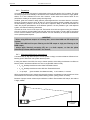
Gradient subwoofers provide an elegant solution to the above issues, based on a
technology that is a simple transposition to sound sources of what has been applied for
decades in microphones: radiated field derives from pressure differences generated
from two (or more) sources:
- Rear radiation is lowered by more than 12 dB, which benefits to stage as well as to
neighbours;
- Direct to reverberant ratio is increased by nearly 6 dB in the low frequency range
(which potentially gives back a kick drum its original “punch”).
However, there are efficiency limitations: gain in lower bandwidth is reduced when
sources become too close in relation to wavelength, and pattern control is limited in
upper bandwidth when both sources interfere destructively in the radiation axis.
Operating bandwidth were efficiency combines with pattern control is around 2 octaves.
Poor correlation between cabinet design and targeted specifications leads to two (and
eventually more) drivers in directional mode producing less energy than one driver in
omnidirectional mode, which is not acceptable for simple practical aspects such as
weight and volume.
It is now 8 years that NEXO has released its first gradient subwoofer – the CD12 -,
complemented since then with the CD18, GEO SUB and RS15. These have been quickly
adopted worldwide as standards, and are considered today as state of the art
subwoofers. This success is a consequence of proper cabinet design and optimized
definition of phase relations through sophisticated DSP algorithms leading to high
directional control and SPL output.
INTRODUCTION
Page 3/55
With RAY SUB patent pending technology, NEXO is again moving one step forward. RAY
SUB technology is about optimizing positioning and phase relationship of radiating
surfaces in vented enclosures, so that acoustic distance from rear to front sections
always increases as frequency decreases; consequently, rear and front section always
sum up efficiently – typically 5 dB gain from rear section in the forward direction – and
cancel in the rearward direction.
Used as a single cabinet, RAY SUB Technology allows the same cabinet to be configured
for any polar pattern, omnidirectional as a standard direct radiating subwoofer when
speakers are facing the audience, or highly directional when cabinet is rotated speakers
sideways or upwards.
Used in arrays, RAY SUB subwoofers can be set back to back, front to front, in vertical
columns, and beam-steered upwards or downwards provided column length is sufficient.
NEXO RAY SUB technology brings a never achieved low frequency directional control to
the sound reinforcement industry, raising one more time NEXO standards.
Page 4/55
INTRODUCTION
SAFETY ISSUES
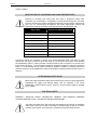
IMPORTANT NOTICE CONCERNING HIGH SOUND PRESSURE LEVELS
Exposure to extremely high noise levels may cause a permanent hearing loss.
Individuals vary considerably in susceptibility to noise-induced hearing loss, but nearly
everyone will lose some hearing if exposed to sufficiently intense noise for a sufficient of
time. The U.S. Government’s Occupational and Health Administration (OSHA) has
specified the following permissible noise level exposures: Sound Duration Per
Day In Hours
Sound Level dBA, Slow Response
8
90
6
92
4
65
3
97
2
100
1½
102
1
105
½
110
¼ or less
115
According to OSHA, any exposure in excess of the above permissible limits could result in some
hearing loss. Ear plugs or protectors to the ear canals or over the ears must be worn when operating
this amplification system in order to prevent a permanent hearing loss, if exposure is in excess of the
limits as set forth above. To ensure against potentially dangerous exposure to high sound pressure
levels, it is recommended that all persons exposed to equipment capable of producing high sound
pressure levels such as this amplification system be protected by hearing protectors while this unit is in
operation.
SYSTEM RIGGING SAFETY RULES
Before use of RS Subwoofers, please ensure that anyone involved in system deployment
understands the rigging and stacking Safety rules as described in the ”RS18
HARDWARE, SAFETY FIRST” section. Failure to do this exposes people to potential
injury or death.
ELECTRICAL SAFETY
WARNING ! NX242-ES4 DIGITAL CONTROLLER, NXAMP4x1 AND NXAMP4x4 POWERED
CONTROLLERS ARE CLASS 1 APPARATUS AND MUST BE EARTHED.
The green and yellow wire of the mains cord must always be connected to an installation
safety earth or ground. The earth is essential for personal safety as well as the correct
operation of the system, and is internally connected to all exposed metal surfaces.
INTRODUCTION
Page 5/55
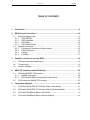
TABLE OF CONTENTS
1
Introduction.......................................................................................................................8
2
RS18 General Instructions.............................................................................................10
2.1
Mounting Rigging Plate .............................................................................................10
2.1.1
RS18 Painted .....................................................................................................10
2.1.2
RS18 Carpeted ..................................................................................................12
2.1.3
RS18 Dolly .........................................................................................................14
2.1.4
RS18 Wheel Board ............................................................................................15
2.2
Speaker connection...................................................................................................16
2.2.1
Configuring Connector and Owner plates..........................................................16
2.2.2
RS18 connectors................................................................................................16
2.2.3
Cabling ...............................................................................................................17
2.2.4
Example .............................................................................................................17
3
4
Amplifier selection for use with RS18 ..........................................................................18
3.1
RS18 recommended amplification ............................................................................18
3.2
Current rating.............................................................................................................18
3.3
Amplifier settings .......................................................................................................18
NEXO TD Controllers and RS18 Setups.......................................................................20
4.1
RS18 and NXAMP TDControllers .............................................................................20
4.1.1
NXAMP connectors............................................................................................20
4.1.2
RS18 and NXAMP recommended configurations .............................................20
4.2
5
RS18 setups on NXAMP TDControllers ...................................................................20
Connection diagrams.....................................................................................................21
5.1
RS18 with NX242-ES4 TD Controller (Stereo Omni Mode) .....................................21
5.2
RS18 with NX242-ES4 TD Controller (Stereo Directional Mode).............................22
5.3
RS18 with NXAMP4x4 (Stereo Omni Mode) ............................................................23
5.4
RS18 with NXAMP4x4 (Stereo Directional Mode) ....................................................24
Page 6/55
6
INTRODUCTION
RS18 Rigging Instructions ............................................................................................ 25
6.1
SAFETY FIRST ........................................................................................................ 25
6.1.1
Flown Systems Safety....................................................................................... 25
6.1.2
Ground Stacking Safety .................................................................................... 26
6.1.3
Contacts ............................................................................................................ 27
6.2
Flying RS18 arrays ................................................................................................... 28
6.2.1
Hoist Rating ....................................................................................................... 28
6.2.2
Connecting first RS18 to bumper ...................................................................... 28
6.2.3
........................................................................................................................... 28
6.2.4
Adjusting rigging point for horizontality ............................................................. 29
6.2.5
Flying subsequent RS18s ................................................................................. 29
6.3
7
8
Testing and Maintenance of the RS18 flying system ............................................... 32
General guidelines for subwoofer design................................................................... 33
7.1
Low Frequency Issues.............................................................................................. 33
7.2
Gradient Subwoofers benefits .................................................................................. 34
7.3
Monophonic Design .................................................................................................. 34
7.4
Stereo Design ........................................................................................................... 35
RAY SUBs implementation ........................................................................................... 36
8.1
Omnidirectional Mode............................................................................................... 36
8.1.1
Single RS18....................................................................................................... 36
8.1.2
RS18 arrays....................................................................................................... 36
8.2
Directional Mode....................................................................................................... 36
8.2.1
Single RS18....................................................................................................... 36
8.2.2
RS18s pair......................................................................................................... 37
8.2.3
RS18s arrays..................................................................................................... 39
8.3
Steered RS18s arrays .............................................................................................. 39
8.3.1
Steering technique ............................................................................................ 39
8.3.2
Delay values implementation ............................................................................ 40
8.3.3
Coverage result ................................................................................................. 41
8.4
Aligning RS18s with main system ............................................................................ 41
8.4.1
NEXO systems acoustic reference point........................................................... 41
8.4.2
Precautions........................................................................................................ 42
8.4.3
Alignment with distance measurement ............................................................. 42
8.4.4
Alignment with phase measurement ................................................................. 43
8.5
Recommended installation tools and equipment ..................................................... 43
INTRODUCTION
9
Page 7/55
RS18 System Check List................................................................................................44
9.1
Are the NX Digital TDcontrollers properly configured? .............................................44
9.2
Are the amplifiers properly configured? ....................................................................44
9.3
Are the amps and the NX properly connected? ........................................................44
9.4
Are the speakers properly connected? .....................................................................44
9.5
Final Pre-Sound Check Check..................................................................................45
10
RS18 Technical Specifications..................................................................................46
10.1
System specifications................................................................................................46
10.2
Dimensions................................................................................................................47
10.3 RS18 Accessories .....................................................................................................48
10.3.1 RS18-BUMPER..................................................................................................48
10.3.2 RS18 Push-Pins.................................................................................................48
10.3.3 RS18-FPLATES .................................................................................................49
10.3.4 RS18-FRONT WHEELBOARD..........................................................................50
10.3.5 RS18-DOLLY .....................................................................................................50
10.4 NX242-ES4 Digital TDController...............................................................................51
10.4.1 Specifications .....................................................................................................51
10.4.2 Front and Rear Panel view ................................................................................51
10.5 NXAMP4x1 & NXAMP4x4 Powered Digital TDControllers.......................................52
10.5.1 Specifications .....................................................................................................52
10.5.2 Front and Rear Panel view ................................................................................53
11
RS18 Parts & Accessories List..................................................................................54
11.1
Modules & Control Electronics List ...........................................................................54
11.2
Accessories List ........................................................................................................54
12
USER NOTES...............................................................................................................55
Page 8/55
1
INTRODUCTION
INTRODUCTION
Thank you for selecting a NEXO RS18 Subwoofer System. This manual is intended to provide you with
necessary and useful information about your RS System, which includes the following products:
•
RS18 is a Directivity Configurable Subwoofer, which comprises two 18” (46cm) long
excursion Neodynium direct radiating drivers mounted in a dual volume vented enclosure
with aerodynamic profiled vents; its coverage ranges from omnidirectional to highly
directional and its frequency response extends from VLF to LF ranges. Two versions are
available (Touring and Fix installations), with two finishing for both versions (carpeted or
painted).
•
a full range of accessories that provides safe, flexible and simple means of transporting and
installing RS18 subwoofers in fixed installation as well as in touring applications. These
include flying hardware, dolly and wheelboard.
INTRODUCTION
Page 9/55
As for all NEXO systems, the RS18 is controlled, powered and monitored by dedicated NEXO
TDControllers:
•
NX242-ES4 Digital TDController provides comprehensive control of RS18 loudspeakers in multiple
configurations. It allows EthersoundTM digital audio networking, as well as remote control for all units
in the network. It has 2 analogue / 4 digital inputs and 4 analogue / 4 digital outputs;
IMPORTANT : NX242 must be equipped with NX-Tension Card to access RS18 directional
mode setups
•
NXAMP4x1 and NXAMP 4x4 are Powered Digital Controllers, providing full control and amplification
for RS18 in multiple configurations. Both devices feature 4 analogue inputs and 4 speaker
outputs.When equipped with optional card, 4 digital inputs in EthersoundTM digital audio network
format as well as remote control for all units in the network become available.
For a complete description of these controllers, please refer to User Manuals. The NX242 and NXAMP
DSP algorithms and parameters are fixed in software and updated regularly: Please consult the NEXO
web site (www.nexo.fr) for the latest software releases.
Please devote your time and attention to reading this manual. A comprehensive understanding of RS18
specific features will help you to operate your system at its full potential.
GeoD Passive mode
Crossover 80Hz
Page 10/55
2
RS18 GENERAL INSTRUCTIONS
RS18 GENERAL INSTRUCTIONS
2.1
Mounting Rigging Plate
IMPORTANT
IN ORDER TO PREVENT SCREWS FROM GETTING LOOSE, USE BLOCKING LIQUID LOCTITETM
243 OR EQUIVALENT FOR ALL SCREWS USED WITH RS18 ACCESSORIES.
2.1.1
RS18 Painted
•
Tools: Allen Key 6mm.
•
Remove the twelve screws on each side of RS18.
•
•
Remove the four screws on each side of RS18.
RS18 GENERAL INSTRUCTIONS
•
Insert Spacer between cabinet and Rigging plates.
•
Fill each screw hole with Loctite 243 or equivalent.
•
Tighten the 6 screws alternately, at the rate of 4 revolutions per screw.
•
Fill each screw hole with Loctite 243 or equivalent.
•
Insert the 8 handles washers and screws and tight them.
Page 11/55
INSTALLING PAINTED RS18 RIGGING PLATES
IMPORTANT
RS18 handles must not be used to fly RS18’s (through illegal use of straps for example)
Page 12/55
RS18 GENERAL INSTRUCTIONS
2.1.2
RS18 Carpeted
•
Tools: Allen Key 6mm.
•
Remove the twelve screws on each side of RS18.
•
Remove the four screws on each side of RS18.
RS18 GENERAL INSTRUCTIONS
•
Fill each screw hole with Loctite 243 or equivalent.
•
Tighten the 6 screws alternately, at the rate of 4 revolutions per screw.
•
Fill each screw hole with Loctite 243 TM or equivalent.
•
Insert the 8 Handles washers and screws and tight them.
Page 13/55
INSTALLING CARPETED RS18 RIGGING PLATES
IMPORTANT
RS18 handles must not be used to fly RS18’s (through illegal use of straps for example)
Page 14/55
RS18 GENERAL INSTRUCTIONS
2.1.3
RS18 Dolly
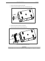
IMPORTANT
TRANSPORTING RS18 ON DOLLY REQUIRES THAT FLYING PLATES ARE INSTALLED
ON ALL CABINETS SO THAT RS18’S CAN BE SECURED TOGETHER:
RS18 DOLLY IS DESIGNED FOR UP TO 3 RS18’S AND BUMPER;
NEVER EXCEED THESE QUANTITIES.
12-
•
The first RS18 must be locked to the RS18 dolly using 4 push-pins according to below drawing;
•
Subsequent RS18s are stacked on top using four push-pins per additional cabinet to secure the
assembly.
•
Bumper is to be attached to the top cabinet.
RS18 GENERAL INSTRUCTIONS
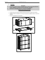
2.1.4
RS18 Wheel Board
•
Pull wheel board lockers inwards;
•
Maintain lockers while positioning wheel board on RS18 front panel ;
•
Release lockers.
IMPORTANT
ENSURE WHEEL BOARD IS PROPERLY LOCKED TO RS18
Page 15/55
Page 16/55
2.2
RS18 GENERAL INSTRUCTIONS
Speaker connection
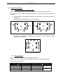
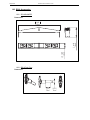
2.2.1
Configuring Connector and Owner plates
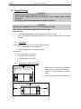
Owner and connector plates can be exchanged depending on chosen directional configuration.
Please note that connector plates can pass through the holes, it is therefore not required to unsolder the
connectors.
•
Directional Mode : it is recommended to install the connector panel on the side which supports the
rigging plates;
•
Connection side is always opposite to FOH (main lobe direction)
Top View
Top View
SP4
Connector
SP4
Connector
FOH
FOH
REAR
Speaker
FRONT
Speaker
FRONT
Speaker
REAR
Speaker
CONNECTOR PLATE IN DIRECTIONAL MODE
•
Omni Mode: it is recommended to install the connector panel on the side opposite to the drivers
(factory default configuration)
SP4
Or
SP4
FOH
CONNECTOR PLATE IN OMNI MODE
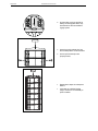
2.2.2
RS18 connectors
RS18 is connected through Speakon NL4FC plugs (not supplied).
Either connector can be used to connect an amplifier or to link to an additional RS18 cabinet.
Connectors are wired as follows:
Speakon NL4F
Omni Mode
Directional Mode
Comment
Driver Next to Connector
Panel
Connectors
1(-)
⇒
18’’ driver Right (-)
18’’ driver Rear (-)
1(+)
⇒
18’’ driver Right (+)
18’’ driver Rear (+)
2(-)
⇒
18’’ driver Left (-)
18’’ driver Front (-)
⇒
18’’ driver Left (+)
18’’ driver Front (+)
2(+)
Driver Opposite to
Connector Panel
RS18 GENERAL INSTRUCTIONS
Page 17/55
DIRECTIONAL
MODE
OMNI
MODE
2.2.3
Cabling
•
NEXO recommends the exclusive use of multi-conductor cables to connect the system: the cable kit
is compatible with all the cabinets, and there is no possible confusion between Front and Rear
drivers.
•
Cable choice consists mainly of selecting cables of the correct sectional dimension (size) in relation to
the load resistance and the cable length. Too small a cable section will increase both its serial
resistance and its capacitance; this reduces the electrical power delivered to the loudspeaker and can
also induce response (damping factor) variations.
•
For a serial resistance less or equal to 4% of the load impedance (damping factor = 25), the
maximum cable length is given by:
Lmax = Z x S
•
2.2.4
S in mm2, Z in Ohm, Lmax in meters
The table below indicates these values, for 3 common sizes.
Load Impedance (Ω)
2
Cable section
Maximum Length (meters)
4
8
2,5 mm² (AWG #12)
5
10
20
4 mm² (AWG #10)
8
16
32
Example
•
Each RS18 driver has a 8 Ohms nominal impedance; in omni mode, both loudspeakers can be
driven in parallel on one amplifier channel, presenting therefore a 8/2 = 4 Ohms load impedance. The
maximum acceptable 2x2.5 mm2 (AWG #12) cable length Lmax for RS18 with its 2 drivers in parallel is
10 meters.
•
When driven in directional mode, RS18 requires 2 amplifier channels, presenting therefore two
independent 8 Ohm load impedances. The maximum acceptable 4x1.5 mm2 (AWG #110) cable
length Lmax for RS18 with its 2 drivers driven independently is 32 meters.
IMPORTANT
Long speaker cables induce capacitive effects – up to hundreds of pF depending on the
quality of the cable - with a low-pass-pass effect on high frequencies. If long speaker
cables must be used, ensure that they do not remain coiled while in use.
Page 18/55
3
AMPLIFIER SELECTION FOR USE WITH RS18
AMPLIFIER SELECTION FOR USE WITH RS18
NEXO recommends high power amplifiers in all cases. Budget constraints are the only reason to select
lower power amplifiers. A lower power amplifier will not reduce the chances of driver damage due to
over-excursion, and may actually increase the risk of thermal damage due to sustained clipping. If an
incident occurs on an installation without protection, the fact that amplifiers only generating half their
rated output power (-3dB) are used will not change anything in respect of possible damage. This is due
to the fact that the RMS power handling of the weakest component in the system is always 6 to 10 dB
lower than the amplifier rating.
3.1
RS18 recommended amplification
RS18 is rated for very high power handling and has a 2x8 Ohms nominal impedance.
Nexo recommends amplifiers in agreement with table below:
Recommended
OMNI MODE
DIRECTIONAL MODE
2 x 1250 Watts to 3000 Watts / 8 Ohms or
2 x 1250 to 3000 Watts / 8 Ohms
Amplifier#
1 x RS18
1 x 2500 Watts to 6000 Watts / 4 Ohms (*)
(*) driving both drivers in parallel requires dedicated speaker cable
3.2
Current rating
It is very important that the amplifier behaves correctly under low load conditions. A speaker system is
reactive by nature: on transient signals like music it will require four to ten times more instantaneous
current than its nominal impedance would indicate. Amplifiers are generally specified by continuous
RMS power into resistive loads; however the only useful information about current capacity is the
specification into a 2 Ohm load. It is possible to perform an amplifier listening test by loading the amps
with twice the number of cabinets considered for the application (2 speakers per channel instead of one,
4 instead of 2) and running the amps up to the onset of clipping. If the signal does not noticeably
deteriorate, the amplifier is well adapted (overheating after approximately ten minutes is normal but
thermal protection must not operate too quickly after starting this test).
3.3
Amplifier settings
Gain value
Gain is the key to correct alignment of the system. It is especially important to know the gain of all
amplifiers used in your set-up. The tolerance should be about ±0.5 dB. In practice this can be difficult to
achieve because:
•
Some amplifier brands have an identical input sensitivity for models of different power rating (this
infers a different voltage gain for each model). For example, a range of amplifiers with different power
outputs, all having a published input sensitivity of 775mV/0dBm or 1.55V/+6dBm, will have a wide
range of actual gains – the higher the power, the greater the gain.
•
Various other brands may offer constant gain but only within a given product range, for example they
may fit fixed input sensitivity only on their semi-professional amps.
•
Even if a manufacturer applies the constant gain rule to all models, the value selected will not
necessarily be the same as that chosen by other manufacturers.
•
Some products can exhibit manufacturing tolerances for the same model of ±1dB or more. Some
amplifiers may have been modified, possibly without any label indicating the new values. Others may
have gain switches fitted internally where it is impossible for the user to verify the actual setting
without opening the amplifier casing.
•
In cases where you don't know the gain of your amplifier (or want to check it) please follow this
procedure:
1) Unplug any loudspeakers from the amplifier outputs
AMPLIFIER SELECTION FOR USE WITH RS18
Page 19/55
2) With a signal generator, feed a sine wave at 1000Hz at a known voltage (say 0.5V) to
the input of the amplifier under test
3) Measure the voltage at the output of the amplifier
4) Calculate the gain using the formula Gain = 20 * LOG10(Vout/Vin).
Some examples:
Vin / Gain
0.1 V
20dB
1V
26dB
2V
32dB
4V
37dB (1.4V sensitivity / 1350Wrms)
7.1 V
0.5 V
5V
10 V
20 V
35.4 V
1V
10 V
20 V
40 V
70.8 V
Remember that constant sensitivity settings will give a different gain value when the amplifier power is
different.
NEXO recommends low gain amplifiers: +26dB is recommended, as it is at the same time adequately
low and quite common amongst amplifier manufacturers. This gain setting improves signal to noise ratio
and allows all preceding electronic equipment, including the NX242-ES4 TDcontroller, to operate at
optimum level. Remember that using a high gain amplifier will raise the noise floor proportionally.
Operating Mode
Most two channel amplifiers available on the pro-audio market have the following operating modes:
•
Stereo: two fully independent channels deliver identical power into identical loads
•
Bridge-Mono: the second signal channel processes the same input as the first channel, but with
reversed phase. The (single) load is connected between the two positive channel outputs using a
suitable connection. While the total output of the amplifier remains the same, the available output
voltage, the minimum impedance that can be connected and the voltage gain are doubled as
compared with stereo operation. Typically, only channel 1 input is active. Positive and negative output
connections vary depending on amplifier manufacturers.
•
NEXO does not recommend Bridge Mono Mode unless amplifier power is clearly not sufficient.
IMPORTANT
When in Bridge-Mono mode, check your amplifier user manual for proper connection of
outputs 1(+) and (2+) in relation to input phase.
•
Parallel-mono: the output terminals of the two channels are configured in parallel using an internal
relay. The (single) load is connected either to the output of channel 1 or to that of channel 2 (as if in
stereo). While the total output of the amplifier remains the same the output voltage level is also the
same as in stereo mode. The minimum impedance that can be connected is reduced by half due to
the fact that current capability is doubled. Typically, only channel 1 input is active.
•
NEXO does not recommend Parallel-Mono Mode for RS18 amplification.
Warning on amplifiers signal processing features
Some high-end amplifiers may include signal processing functions similar to those found in the NX242ES4 TDcontroller ("loudspeaker offset integration", "limiter", "compressor," etc.). Moreover, when this
processing is digital, computation latency time can introduce a few milliseconds delay from input to
output. These functions are not adapted to specific system requirements and may interfere with the
complex protection algorithms used in the NX242-ES4.
NEXO do not advise using other protection systems in conjunction with the NX242-ES4 and they should
be disabled.
IMPORTANT
For proper system protection, no latency time or non-linear devices should be inserted
between the output of NX242-ES4 TDController and the input of loudspeakers through
use of DSP modules such as internal amplifier signal processing.
Page 20/55
4
NEXO TD CONTROLLERS AND RS18 SETUPS
NEXO TD CONTROLLERS AND RS18 SETUPS
4.1
RS18 and NXAMP TDControllers
NEXO Powered TDControllers NXAMP 4X1 & 4X4 are integrated solutions for Control and amplification
for all NEXO speaker ranges.
NXAMP4x1 and NXAMP4x4 power capability is listed in the table below:
Mode
NXAMP4x1
4 Channels
Bridge Stereo
4 x 650 Watts / 8 Ohms
2 x 1800 Watts / 8 Ohms
4 x 900 Watts / 4 Ohms
2 x 2600 Watts / 4 Ohms
4 x 1300 Watts / 2 Ohms
NXAMP4x4
4 x 1900 Watts / 8 Ohms
2 x 6800 Watts / 8 Ohms
4 x 3400 Watts / 4 Ohms
2 x 8000 Watts / 4 Ohms
4 x 4000 Watts / 2 Ohms
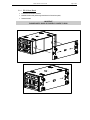
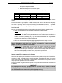
4.1.1
NXAMP connectors
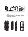
NXAMP4x1 and NXAMP4x4 rear panels feature:
•
4 analog inputs / outputs (links) on XLR3 connectors;
•
4 digital inputs / outputs on RJ45 connectors with optional card;
•
4 speaker level outputs on NL4FC connectors.
Figure below shows connectors implementation on the rear panel.
4.1.2
1 x RS18
2 x RS18
3 x RS18
4.2
RS18 and NXAMP recommended configurations
OMNI MODE
DIRECTIONAL MODE
1 channel of NXAMP4x1 in Bridge Stereo Mode
2 channels of NXAMP4x1 in Bridge Stereo Mode
1 channel of NXAMP4x4 in 4 channels mode
2 channels of NXAMP4x4 in 4 channels mode
2 channels of NXAMP4x1 in Bridge Stereo Mode
2 channels of NXAMP4x1 in Bridge Stereo Mode
2 channels of NXAMP4x4 in 4 channels mode
2 channels of NXAMP4x4 in 4 channels mode
2 channels of NXAMP4x4 in 4 channels mode
2 channels of NXAMP4x4 in 4 channels mode
RS18 setups on NXAMP TDControllers
At RS18 release time (February 2010), 60 setups combining RS18 with NEXO speakers are available in
NX242-ES4 / NXAMP load 2.52.
Please consult www.nexo-sa.com periodically for upgrade releases.
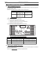
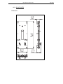
CONNECTION DIAGRAMS
RS18 with NX242-ES4 TD Controller (Stereo Omni Mode)
FROM AMPLIFIERS
TO AMPLIFIERS
N.C. N.C.
+2- +1-
OUT
OUT
RIGHT LEFT
LEFT
5.1
CONNECTION DIAGRAMS
RIGHT
5
Page 21/55
STEREO
LEFT
STEREO
RIGHT
SP4
SP4
SP4
SP4
SP4
SP4
IN RIGHT IN LEFT
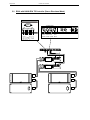
Page 22/55
RS18 with NX242-ES4 TD Controller (Stereo Directional Mode)
FROM AMPLIFIERS
TO AMPLIFIERS
LEFT
REAR
LEFT
FRONT
RIGHT
REAR
+4- +3- +2- +1RIGHT
FRONT
5.2
CONNECTION DIAGRAMS
OUT
OUT OUT
OUT
RIGHT RIGHT LEFT
LEFT
FRONT REAR FRONT REAR
IN RIGHT IN LEFT
STEREO
LEFT
STEREO
RIGHT
SP4
SP4
SP4
SP4
SP4
SP4
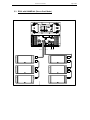
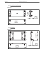
CONNECTION DIAGRAMS
5.3
Page 23/55
RS18 with NXAMP4x4 (Stereo Omni Mode)
OUT B
OUT A
IN B IN A
SP4
SP4
SP4
SP4
SP4
SP4
SP4
SP4
SP4
SP4
SP4
SP4
Page 24/55
5.4
CONNECTION DIAGRAMS
RS18 with NXAMP4x4 (Stereo Directional Mode)
OUT B
OUT A
IN B IN A
SP4
SP4
SP4
SP4
SP4
SP4
SP4
SP4
SP4
SP4
SP4
SP4
RS18 RIGGING INSTRUCTIONS
6
Page 25/55
RS18 RIGGING INSTRUCTIONS
Before proceeding with assembly of RS18 arrays, please ensure that the components are present and
undamaged. A component list is appended to this manual. In the event of any shortage, please contact
your supplier.
For maximum efficiency the RS18 rigging system requires three experienced persons for set-up:
typically one motor hoist operator, and one RS18 operator per side of the array. Good synchronisation
and crosscheck between the operators are key elements for a reliable and safe set-up.
6.1
SAFETY FIRST
RS18 Rigging System structural computations and related documents are available in Geosoft2 or at
Nexo ([email protected]) upon request.
We include this section to remind you of safe practice when flying the RS18 system. Please read it
carefully. However, user must always apply his or her knowledge, experience and common sense. If in
any doubt, seek advice from your supplier or NEXO agent.
This manual offers guidance only for RS18 RAYSUB systems. References in this manual to other
rigging equipment such as motor hoists, steels, shackles etc. are made to clarify the description of
RS18 procedures. The user must ensure that operators are properly trained by other agencies in the
use of these items.
The RS18 Rigging System has been optimised for the deployment of vertical arrays of RS18
loudspeakers. No angle adjustment is allowed between cabinets.
The RS18 Rigging System is a professional precision tool set, and should be handled with extreme
care. Only persons who are fully conversant with the operation of the RS18 Rigging System and
provided with suitable safety equipment should deploy RAYSUB Arrays. Misuse of the RS18 Rigging
System could lead to dangerous consequences.
Used and maintained correctly, the RS18 Rigging System will give many years of reliable service in
portable systems. Please take the time to read and understand this manual.
6.1.1
Flown Systems Safety
•
Always inspect all the rigging components and cabinets for damage before assembly. Pay special
attention to the lifting points, and safety clips. If you suspect that any of the components are damaged
or defective, DO NOT USE THE AFFECTED PARTS. Contact your supplier for replacements.
•
Read this manual carefully. Also be familiar with the manuals and safe working procedures for any
ancillary equipment that will be used with the RS18 Rigging System.
•
Ensure that all local and National regulations regarding the safety and operation of flying equipment
are understood and adhered to. Information on these regulations can usually be obtained from Local
Government Offices.
•
When deploying a RS18 system always wear protective headwear, footwear and eye protection.
•
Do not allow inexperienced persons to handle a RS18 system. Installation personnel should be
trained in loudspeaker flying techniques and should be fully conversant with this manual.
•
Ensure that motor hoists, hoist control systems and ancillary rigging components are currently
certified as safe and that they pass a visual inspection prior to use.
•
Ensure that the public and personnel are not allowed to pass beneath the system during the
installation process. The work area should be isolated from public access.
•
Never leave the system unattended during the installation process.
•
Do not place any object, no matter how small or light, on top of the system during the installation
procedure. The object may fall when the system is flown and is likely to cause injury.
•
Secondary safety steels must be installed once the system has been flown to the operating height.
Secondary steels must be fitted irrespective of requirements of the local safety standards applicable
to the territory.
Page 26/55
RS18 RIGGING INSTRUCTIONS
•
Ensure that the system is secure and prevented from pivoting around the motor hoist.
•
Avoid any form of excessive dynamic loading to the assembly (structural computations on RS18
Rigging System are based on a 1/1.2 factor for hoist or motor acceleration).
•
NEVER attach any item to the RS18 system other than the RS18 accessories.
•
When flying outdoor systems ensure that the system is not exposed to excessive wind or snow loads
and is protected from rainfall.
•
The RS18 Rigging System requires regular inspection and testing by a competent test centre. NEXO
recommend that the system is load tested and certified annually or more frequently if local regulations
require.
•
When de-rigging the system ensure that the same duty of care is given to the procedure as for the
installation. Pack RS18 components carefully to prevent damage in transit.
6.1.2
Ground Stacking Safety
Statistically, many more injuries occur due to unstable ground stacked PA systems than those
associated with flown systems. There are several reasons for this fact, however the message is clear:
•
Always survey the supporting structure upon which a ground stack is to be built. Always look beneath
PA wings to inspect the deck support and if necessary ask for the stage scrims and dressings be
removed to allow access.
•
If the stage surface slopes, as it does in some theatres, ensure that the system is prevented from
sliding forwards due to vibration. This may require the fitting of timber battens to the stage floor.
•
For outdoor systems ensure that that the system is protected from wind forces which might cause the
ground stack to become unstable. Wind forces can be huge, especially upon large systems, and
should never be underestimated. Observe meteorological forecasts, calculate the “worst case” effect
upon the system prior to erection and ensure that the system is secured appropriately.
•
Take care when stacking cabinets. Always employ safe lifting procedures and never attempt to build
stacks without sufficient personnel and equipment.
•
Never allow anyone, whether operators, artists or members of the public to climb onto a ground
stacked PA system. Anyone who needs to climb over 2m (6 ft) high should be fitted with suitable
safely equipment including a clip-on harness. Please refer to local Health and Safety legislation in
your territory. Your dealer can help with advice on access to this information.
•
Apply the same attention to all safety matters when de-stacking systems.
•
Be aware that safety procedures are as important in the truck and in the warehouse as they are at the
venue.
RS18 RIGGING INSTRUCTIONS
-
Page 27/55
IMPORTANT
specifically rated
All RS18 Accessories are
in agreement with structural
computations.
Never use other accessories – including push-pins - when assembling RS18 cabinets
than the ones provided by NEXO: NEXO will decline responsibility over the entire
RS18 accessory range if any component is purchased from a different supplier.
6.1.3
Contacts
Correct training is fundamental to safe practise when working with loudspeaker flying systems. NEXO
recommend that users contact local industry associations for information on specialist courses.
Information for International training agencies can be obtained by contacting either:
The Production Services Association
(PSA),
School Passage,
Kingston-upon-Thames,
KT1 SDU Surrey,
ENGLAND
Telephone: +44 (0) 181 392 0180
Rigstar Training and Testing Center
82 Industrial Dr. Unit 4
Northampton, Massachusetts 01060 U.S.A.
Phone: 413-585-9869 -- Fax: 413-585-9872
[email protected]
ESTA
Entertainment Services & Technology Association
875 Sixth Avenue, Suite 1005
NEW YORK, NY 10001 USA
Phone: 212-244-1505 – Fax: 212-244-1502
[email protected]
Page 28/55
6.2
RS18 RIGGING INSTRUCTIONS
Flying RS18 arrays
-
IMPORTANT
Maximum allowed RS18 quantity to be flown is 12;
RS18 bumper rigging point must be adjusted so that bumper always remains
horizontal;
RS18 flying system forbids angles between adjacent cabinets.
IMPORTANT
RS18 bumper is designed to be flown from one rigging point only.
Motor hoist must be rated to support entire cluster weight.
Required items
•
1 x Bumper (RST-BUMPER18) , 4 Quick release pins 10x25mm included;
•
N Pair of RS18 Rigging Plates (RST-FPLATES18) for N cabinets, 4xN quick release pins 10x25mm
(included).
6.2.1
Hoist Rating
N being RS18 quantity within a cluster, cluster weight is given by:
Wcluster = (30kg/66lbs) + Nx(131kg/289lbs)
including cable weight up to 5kg/11lbs per RS18
Hoist rating is:
•
Up to 3 RS18 cluster = ½ ton hoist;
•
4 to 6 RS18 cluster = 1 ton hoist;
•
7 to 12 RS18 cluster = 2 ton hoist.
6.2.2
Connecting first RS18 to bumper
6.2.3
•
Connect bumper to first RS18 flying system link
plates by using 4 10x25mm quick release pins;
•
ensure the 4 quick release pins are properly
locked;
•
Connect hoist hook to bumper axis (see below)
RS18 RIGGING INSTRUCTIONS
6.2.4
Page 29/55
Adjusting rigging point for horizontality
Before connecting a second cabinet, bumper angle has to be adjusted for perfect horizontality.
This requires that the rigging point is adjusted in the two horizontal directions so that the bumper
remains horizontal within +/-1°. Adding cabinets will improve this tolerance.
Adjusting 0° along the cabinet depth
Adjusting horizontality along cabinet depth is done by properly selecting bumper hole:
GRIDS SAME SIDE
6.2.5
GRIDS ALTERNATE SIDE
Flying subsequent RS18s
•
Lift assembly to sufficient height in
order to connect a second RS18;
•
Position and align second RS18
below assembly;
•
Remove the 4 quick release pins from
the PARKING position so that sliding
connector plate can be moved;
Page 30/55
RS18 RIGGING INSTRUCTIONS
•
On both sides, push the top RS18
sliding connecting plate all the way
downwards into the second RS18
rigging system
•
Insert the 4 quick release pins into
the FLOWN position of second RS18
•
ensure quick release pins are
properly locked;
•
Repeat above steps for subsequent
RS18’s;
•
Lift cluster up to defined rigging
height, and secure it horizontally to
prevent rotation.
RS18 RIGGING INSTRUCTIONS
Page 31/55
•
Secure bumper with secondary safety
steel.
IMPORTANT
Do not attempt to make any change to the bumper rigging point once the cluster is lifted
IMPORTANT
The requirements for secondary safety systems vary with territories. However, the
secondary safety steel MUST have a SWL equivalent or greater than that of the rigging
system
Page 32/55
6.3
RS18 RIGGING INSTRUCTIONS
Testing and Maintenance of the RS18 flying system
•
General: please keep regular maintenance attention to the RS18 flying system in order to provide
long and reliable service. NEXO recommends regular testing of loudspeaker rigging components,
preferably using a suitable test rig coupled with a visual inspection.
•
Fasteners: there are several critical points in the RS18 cabinets; primary concerns are:
- the grid screws attaching the grid to the cabinet;
- the screws attaching the connecting plates to the cabinet.
•
These fasteners should be regularly checked and tightened as necessary.
•
Cleaning: The exterior of the cabinet and the rigging system can be cleaned with a damp cloth
soaked in mild soapy water. On no account use solvent based cleaners , which may damage the
finishing of the cabinet
•
After cleaning, the rigging system must be treated with a suitable lubricant to prevent rusting. NEXO
recommends the use of Scottoil FS365 or equivalent which is a water-based lubricant with a mixture
of machine oil, surfactant and anti-rust treatment.
GENERAL GUIDELINES FOR SUBWOOFER DESIGN
7
7.1
Page 33/55
GENERAL GUIDELINES FOR SUBWOOFER DESIGN
Low Frequency Issues
Even low frequency coverage is amongst the toughest issues in sound system design. Common issues
that are faced in design are as follow:
•
Low frequency radiation is hard to control
efficiently because of wavelength
becoming large (10m / 30ft at 34 Hz) in
relation to sources; and most of available
subwoofers are omnidirectional; this
results in important low frequency
feedback on stage, environmental
problems in outdoor venues and
increased reverberation time in indoor
venues;
•
Stereophonic
implementation
of
subwoofers introduces very strong
interference patterns; these are related to
Left and Right path length difference to
listener location while pressure levels are
comparable for Left and Right arrays;
while always maximum at the center –
where distance to Left and Right arrays
are equal -, pressure level can severely
drop at locations where path length
equals half the wavelength of frequency
of interest. This effect is well-known from
audio-engineers, and often referred to as
“Power Alley”;
•
L(m)
f1=C/2L
In closed venues, room eigen modes
(nulls and max) are dominant over source
location; because these modes depend
on accurate characterization of boundary
surfaces (walls, ceiling, floor), audience
coverage is very hard to predict.
To overcome these difficulties, some common sense
rules can help.
Page 34/55
7.2
GENERAL GUIDELINES FOR SUBWOOFER DESIGN
Gradient Subwoofers benefits
Gradient subwoofers can provide up to 15 dB front to rear average
attenuation (Please refer to Ray Sub technical note for in-detail explanation
on gradient subwoofers).
Low frequency level on stage is therefore significantly reduced on stage, and
in the neighbouring environment in open air venues.
Because of their directional pattern, Gradient subwoofer are also less
sensitive to room eigen modes.
7.3
Monophonic Design
Left and Right subwoofer arrays can be merged into a monophonic system so that interferences no
longer exist.
When using few cabinets, this can be done by installing these cabinets at the centre front stage. If
cabinets are set on the ground in front of the stage, level discrepancy from first to last rows will be
important. Flying cabinets above centre stage will reduce first to last rows discrepancies significantly.
CENTRE STACKED DIRECTIONAL SUBWOOFER
CENTRE FLOWN DIRECTIONAL SUBWOOFER
When using a larger amount of cabinets, these can then be installed all across the stage provided
distance between units does not exceed half the wavelength of the upper frequency limit (1.7m/5.6ft at
100 Hz). Array coverage can then be adjusted geometrically (by curving the array horizontally so that it
matches the audience area, which creates an asymmetrical front stage to rear stage pattern with a “hot”
point on stage) or electronically (by implementing a delay that increase from the centre to the sides,
which creates a symmetrical pattern front to rear). In both cases, omnidirectional subwoofers should be
avoided so low frequency that level on stage does not exceed level in the audience.
CURVED SUBWOOFER ARRAY ACROSS STAGE
STRAIGHT DELAYED SUBWOOFER ARRAY ACROSS STAGE
GENERAL GUIDELINES FOR SUBWOOFER DESIGN
Page 35/55
Main drawback of monophonic designs as the ones described above is inconsistent phase relationship
between subwoofer arrays and main systems over the audience area (lack of impact in the 80Hz-125Hz
bandwidth).
7.4
Stereo Design
If stereophonic implementation has to be maintained, then Left and Right array coverage patterns have
to be as independent as possible – ie coverage overlap from Left to Right has to be minimized.
When using few cabinets, minimizing overlap can
only be achieved with directional devices by
rotating the subwoofers 30° to 45° outwards
(rotating an omnidirectional subwoofer makes no
difference in the coverage pattern).
When using a larger amount of cabinets, Left and Right subwoofers arrays must be designed so that
level drops as much as possible inwards, and is maintained as going outwards. Therefore, main axis
efficiency must be orientated outwards (through use of delays or curving the array outward as in below
figure). Such arrays must be experimented playing one side only to check if above condition is fulfilled,
and then summed left and right for interference evaluation (see below drawings). Although pressure
level will still drop in the centre vicinity, overall level in the audience area is comparable to what occurs
at the centre.
Curved Sub Array
Steered Sub Array
LEFT IMPLEMENTATION MINIMIZING RIGHT COVERAGE
LEFT AND RIGHT SUM
Advantage of stereo design as oppose to mono design is much improved phase relationship between
subwoofer arrays and main systems since distance between them is greatly reduced.
However, it is essential to keep in mind that stereo subwoofer array design always leads to strong
interferences in the centre alley vicinity (a couple of steps left and right of mixing position).
A successful design requires minimizing the audience area over which these interferences occur, and
therefore lots of on-site experimentation.
Page 36/55
8
8.1
RAY SUBS IMPLEMENTATION
RAY SUBS IMPLEMENTATION
Omnidirectional Mode
8.1.1
Single RS18
Omnidirectional Mode implementation should be favoured in configurations where:
-
sufficient depth is not available for directional implementation (proscenium, front stage
etc…);
-
strong rear radiation is not critical.
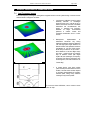
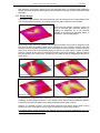
Although wide in both cases, coverage is slightly narrower along RS18’s width than height (see
drawings below).
HORIZONTAL COVERAGE IN OMNI MODE
8.1.2
VERTICAL COVERAGE IN OMNI MODE
RS18 arrays
IMPORTANT
RS18s arrays must be installed with bumper set horizontally and all cabinets at 0°.
Design procedure should be in agreement with what has been described in the preceding section.
See following section on Steered Arrays
8.2
Directional Mode
8.2.1
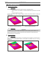
Single RS18
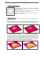
Single RS18 have an asymmetrical pattern in the horizontal plane (ie speakers on the side), which is
tilted 30° off-axis towards speakers direction; vertical pattern (ie speakers facing up or down) is
symmetrical).
HORIZONTAL COVERAGE IN DIRECTIONAL MODE
VERTICAL COVERAGE IN DIRECTIONAL MODE
RAY SUBS IMPLEMENTATION
Page 37/55
IMPORTANT
So that directional behaviour and acoustic load are not altered, no reflecting surface
should be at less than 50cm (20”) from the RS18 side walls and drivers.
In case of stereo configurations, NEXO recommends that speaker side is set outwards to minimize
interference region in stereo designs.
8.2.2
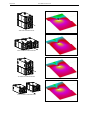
RS18s pair
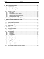
There are four ways of using pairs of RS18s in directional mode: “one side”, “alternate”, “back to back”
and “face to face” (50cm / 20” between grids)
All of these configurations have symmetrical patterns with a smooth 15dB attenuation at the rear over
the entire RS18 bandwidth, but significantly different horizontal coverage.
-
“one side” configuration has a constant -3 dB coverage of 120° from 31.5 Hz to 80 Hz;
-
“back to back” configuration has a -3dB coverage which decreases from 90° at 31.5 Hz to
60° at 80Hz;
-
“alternate” configuration has a constant -3dB coverage of 90° from 31.5Hz to 80Hz;
-
“face to face” configuration has a -3 dB coverage which increases from 90° at 31.5 Hz to
120° at 800 Hz.
Page 38/55
RAY SUBS IMPLEMENTATION
“ONE SIDE CONFIGURATION“
“BACK TO BACK“ CONFIGURATION
“ALTERNATE“ CONFIGURATION“
“FACE TO FACE“ CONFIGURATION
RAY SUBS IMPLEMENTATION
8.2.3
Page 39/55
RS18s arrays
IMPORTANT
RS18s arrays must be installed with bumper set horizontally and all cabinets at 0°.
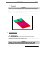
Flying RS18s columns can significantly improve low frequency coverage in the vertical plane, and
therefore over audience depth provided height is sufficient.
A 12 RS18 cluster flown at 10m/30ft will provide a +/- 3dB pressure level deviation at 100Hz over an
audience area 75m/200ft deep while maintaining 15 to 20dB attenuation on stage (see figure below).
12 RS18 “ALTERNATE” CLUSTER OVER 75M/200FT
8.3
Steered RS18s arrays
8.3.1
Steering technique
RS18s arrays must be flown vertically with bumper set horizontally and all cabinets at 0°.
Coverage adjustments can be efficiently implemented through the “steering” technique, which consists
in implementing delays in cabinets to tilt coverage up or down.
IMPORTANT
- “Steering” techniques should not be applied to clusters of less than 3 RS18;
- Coverage control through steering technique increases with cluster height.
Steering can be applied by unit, group of 2 or group of 3 in Omni Mode as well as in Directional Mode.
Page 40/55
RAY SUBS IMPLEMENTATION
θ
θ
t
t
GROUP OF 2 RS18S STEERING
GROUP OF 3 RS18S STEERING
“Steering” delays values for the pairs can easily be computed according to following formula:
τ = h*sin(θ)/C
(metric)
τ is the value to be applied to the second pair
h is the height of tilted elements ( 1.04m for 2 RS18s, 1.56m for 3 RS18s)
C is the speed of sound ( = 343m/s )
8.3.2
Delay values implementation
•
If the coverage is to be tilted down, then top group delay should be set at 0ms and delay should
progressively increase on lower groups.
•
If the coverage is to be tilted up, then lower group delay should be set at 0ms and delay should
progressively increase on upper pairs.
•
Delay value for first group is always 0ms.
•
Delay value for second unit or group is τ
•
Delay values for subsequent units or groups are 2τ, 3τ etc…
Table below lists these values for typical angle values:
TILT ANGLE
1 RS18
DELAY τ (ms)
DISTANCE (cm)
GROUP
DELAY τ (ms)
2 RS18s
DISTANCE (cm)
GROUP
3 RS18s
DELAY τ (ms)
DISTANCE (cm)
0°
5°
10°
15°
20°
25°
30°
35°
40°
45°
0.0
0.1
0.3
0.4
0.5
0.6
0.8
0.9
1.0
1.1
0
5
9
13
18
22
26
30
33
37
0.0
0.3
0.5
0.8
1.0
1.3
1.5
1.7
1.9
2.1
0
9
18
27
36
44
52
60
67
74
0.0
0.4
0.8
1.2
1.6
1.9
2.3
2.6
2.9
3.2
0
14
27
40
53
66
78
89
100
110
RAY SUBS IMPLEMENTATION
8.3.3
Page 41/55
Coverage result
Below figure shows coverage control over distance with a “steering” delay sequence corresponding to a
15° tilt down.
12 RS18 “ALTERNATE” CLUSTER OVER 75M/200FT, STEERED 15° DOWN
8.4
Aligning RS18s with main system
8.4.1
NEXO systems acoustic reference point
The NX TDControllers factory presets are optimised to provide the best possible crossover between the
RS18’as and PS8/PS10/PS15, GeoS8/Geo12 systems. These crossover algorithms are defined for
speaker acoustic reference points being aligned.
The acoustic reference point on all NEXO products is the front of each cabinet, therefore:
•
RS18’s reference point in Omni Mode is center of the front grid
•
RS18’s reference point in Directional Mode is center of the face opposite to connector panel.
RS18 REFERENCE POINT IN OMNI MODE
RS18 REFERENCE POINT IN DIRECTIONAL MODE
Page 42/55
RAY SUBS IMPLEMENTATION
8.4.2
Precautions
It is common to use the AUX send of a mixing desk to drive the Sub section of a PA system. This gives
the mixing engineer more flexibility to set the level of the subbass relative to the main PA, apply special
effects, or to use a different EQ on the Sub. However, it also raises some serious issues for the
performance & safety of the system (mostly time alignment).
At NEXO, great care is taken to design optimum phase alignment from one octave above to one octave
below the crossover frequency point. By doing so, drivers are working perfectly together and providing
the best efficiency possible. It is then up to the user to adjust the delay on the NX TDControllers to
match the physical path difference of the different systems. It is thus possible to get a well adjusted
system, even without measuring instruments.
If RS18s are driven form an AUX output, NX TDController is fed with two signals coming from different
sources. If those two sources (MAIN output & AUX send) are not exactly in phase, delay is introduced
into the crossover between main system and RS18s. It is then mandatory to use proper measurement
tool to optimize phase response.
IMPORTANT
- Before using different outputs of a mixing desk, ensure that MAIN and SUB outputs are
in phase;
- Never add additional low pass filtering on the SUB output or high pass filtering on the
MAIN output;
- Always apply identical processing (EQ etc…) on both outputs, so that the phase
relationship between MAIN and SUB is not altered;
8.4.3
Alignment with distance measurement
The fastest way to align RS18 arrays to a main system is simply to measure distance difference from
listening point to RS18 and main system reference points.
r1 being the distance from GEO S12 array to listener position, and r2 being the distance from RS18 to
listener position, the distance difference is then r1–r2 (specified meters or feet).
•
r1 > r2, the delay should be set on the RS18 TDcontroller channel.
•
r1 < r2, the delay should be set on the GEO S12 TDcontroller channel
•
∆t = (r1-r2)/C
gives conversion from distance to delay
r1, r2 in meters, C = 343 m/s.
NEXO recommends that main system and subwoofer systems are adjusted so that arrivals from RS18
and PS/GEOS are coincident at a fairly distant listening position (mixing position or further).
Because of proper acoustic reference point definition in NEXO TDControllers DSP setups, this method
is highly reliable.
r1
r2
Mixing position
or further
RAY SUBS IMPLEMENTATION
8.4.4
Page 43/55
Alignment with phase measurement
Phase measurement with real time FFT analyzer can also provide reliable measurements, provided:
•
measurement microphone is set on the ground to avoid floor interference in the reading;
•
floor is perfectly rigid (concrete);
•
measurement microphone is set far from any walls / ceiling, or inside angles / corners;
•
coherence values are high (typically above 75%).
If one of above conditions is not respected, then distance measurement should be preferred.
8.5
Recommended installation tools and equipment
•
Tape measure – should be 30m/100ft in length and be of durable fibre material. Have one per array
available to speed up the installation process.
•
Laser Inclinometer – For measuring vertical and horizontal angles in the venue. An ideal product is
the Calpac ‘Laser projecting a dot’ version which costs approximately 60 €.
•
Spirit level – used to ascertain the trueness of the surface from which the angle measurements
originate.
•
Rangefinder measuring device – either a Disto type laser measure or an optical laser rangefinder can
be used. Devices such as the Bushnell ‘Yardage Pro’ sports rangefinders provide sufficiently
accuracy and are easy to use. They have the additional advantage of working very well in bright
sunlight.
•
Electronic calculator with trigonometric functions to calculate the height from ground level to points in
the room. The formula to calculate height of a point from measured angle and distance is:
•
Height of point = Sin(vertical angle in degrees) x distance to point
•
NB: Take care when using spreadsheets as they calculate using radians by default. To convert
degrees to radians use the formula:
•
Angle (in radians)=3.142 x Angle (in degrees)/180
•
Computer – Laptop or Desktop PC running Windows 2000 or XP with the current version of NEXO
GeoSoft2 installed. It is not possible to configure a Geo tangent array properly without using
GeoSoft2. Note that, when GeoSoft2 designs are prepared prior to arrival at the venue, it is often
necessary to modify or update the design to accommodate special circumstances. A PC is absolutely
essential to make such changes.
•
Audio Analysis Software – recommended but not absolutely essential, programs such as Easera
SystuneTM, SpectralabTM or WinMLSTM enable rapid and detailed analysis of the installation. Consider
taking a training course in using one of these tools if you are not already competent with them – it will
pay dividends in increased performance of the system.
Page 44/55
9
RS18 SYSTEM CHECK LIST
RS18 SYSTEM CHECK LIST
It is essential to execute all these check steps prior to a sound check on the “front end” to the system.
Following this checklist step by step will prevent many troubles and will save time in the end.
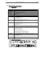
9.1
Are the NX Digital TDcontrollers properly configured?
IMPORTANT
If you must change any of the parameters listed below, make sure that you use the same
values on all NX’s.
Output Assignment
1
2
3
4
RS18 4 Channels Omni Mode
NX Setup / NXChannel
RS18-1
RS18-2
RS18-3
RS18-4
RS18 Stereo Directional Mode
RS18 Rear Left
RS18 Front Left
RS18 Rear Right
RS18 Front Right
Output parameters
Output
Amp
Amp
Global
Global
Sense
Array EQ
Label
Gain (2)
Power (2)
Gain
Delay
Gain
(3)
(4)
26 dB
refer to amp
0 dB
0 ms
0 dB
0
5 bars
All channels
Headrom
(1) Local gain and delay values are inter-locked on channel 1&2 and 3&4 in Directional Mode
(2) values for recommended amplifier gain and power : should be set in agreement with selected
amplifiers specifications
(3) Should be in agreement with implemented cluster; acts on a shelving filter designed to compensate
for LF coupling.
(4) Disabled when using digital inputs.
9.2
Are the amplifiers properly configured?
Freq. Band
All channels
9.3
Mode
Gain Switch
Limiter
High Pass
Stereo
26 dB
None
None
Are the amps and the NX properly connected?
Check that the sense lines on the NX’s are properly connected by applying a signal to the
corresponding output and verify that the correct Sense LED illuminates.
9.4
Are the speakers properly connected?
•
Attach the first serie of modules to the bumper
•
Before flying, verify that all drivers of all modules are functioning properly.
•
Make sure that each RS18 driver is producing proper summation in omni mode:
•
The two RS18 individual 18” driver should sum up by 6 dB;
•
Doubling RS18 quantity (2, 4 and so on) should also produce 6 dB gain.
•
Make sure that each RS18 is producing the proper front/rear summation in directional mode:
RS18 SYSTEM CHECK LIST
9.5
Page 45/55
•
when listening from behind the system, switch the front drivers in and out. You should hear a
reduction in the LF range when the both front and rear drivers are on as compared to when the rear
drivers only are on;
•
When listening from the front, you should hear a strong increase in the LF range when connecting the
rear drivers.
•
Raise the bumper, attach the next series of modules and repeat the above checks.
•
Make sure that these series of modules sum properly with the modules above them.
Final Pre-Sound Check Check
•
Play a CD track (preferably generous and periodic in the LF content) on the SUB output, mono left,
mono right and then both sides:
•
both sides must sound strictly identical when listening at the center;
•
level must not decrease at the center when playing left and right simultaneously as opposed to one
side only.
•
Play the same CD track on the MAIN system, on the SUB system, then on both:
•
Inverting polarity on one of these outputs – MAIN or SUB - should always result in a massive
difference near the crossover point.
Page 46/55
RS18 TECHNICAL SPECIFICATIONS
10 RS18 TECHNICAL SPECIFICATIONS
10.1 System specifications
RS18 PRODUCT FEATURES
Components
Height x Width x Depth
2 x 18” (46cm) long excursion neodynium 8Ω drivers
520 x 1403 x 732mm (20.46” x 55.24” x 28.81”) with handles
520 x 1238 x 732mm (20.46” x 49.92” x 28.81”) without handles
Shape
Weight
Rectangular
Net Weight with handles 105Kg (231.5 lbs)
Net Weight with rigging system 126Kg (278 lbs)
Net Weight without accessories 90Kg (199 lbs)
Connectors
4 x NL4MP SPEAKON 4 pole on two connection plates (In & Through)
Construction
Baltic Birch ply finish with structured black coating
Dark grey carpet finish also available
RS18 with NX242-ES4 TDcontroller or NXAMP SYSTEM SPECIFICATION
Omni
Directional
Frequency Response @ -3db [a]
32Hz–100Hz
32Hz-100Hz
Usable Range @ -6db [a]
29Hz–250Hz
29Hz–150Hz
Sensitivity 1W @ 1m [b]
105dB SPL Nominal
103dB SPL Nominal
Peak SPL @ 1m [b]
143–146dBPeak
140–143dBPeak
(2x1250 to 2 x 3000W/8Ω)
(2x1250W to 2 x 3000W/8Ω)
Dispersion
Omni & Directional pattern over the entire useable bandwidth depending on the NX242
or NXAMP TDcontrollers setup. (two channels of the NX242ES4 or NXAMP are
required to process directional setups)
Directivity Index [c]
1.5<Q<2
Crossover Frequency:
From 75Hz to 100Hz
From 75Hz to 100Hz
Nominal Impedance
2 x 8Ω
2 x 8Ω
Recommended Amplifiers
1 amplifier channel is required for omni
2 amplifier channels are required for
mode operation, rated at 2000 to 4000 Watts directional mode operation, each rated at
into 4Ω
1000 to 2000 Watts into 8Ω per channel
1.7dB<DI<3dB
Q=4.3
DI=5.3dB
NX242 or NXAMP TDcontrollers preset
dependent
SYSTEM OPERATION
Electronic Controller
NX242ES4 Digital TDcontroller & NXAMP Powered Digital TDcontroller presets are
precisely matched to RS18 and include sophisticated protection systems.
Using RS18 without a properly connected TDController will result in poor sound quality
and can damage components.
Speaker Cables
1-/1+ = Right or Rear
2-/2+ = Left or Front
The RS18 must use separate cables to the main system
Accessories
Bumper – Flying Plates – Dolly - Front Wheel Board
Rigging system [d]
Please refer to the user manual before any operation
SHIPPING & ORDERING
Packaging
RS18s are packaged individually.
Order RS18-C (finished grey carpeting) or RS18-P (finished in black structured coating)
As part of a policy of continual improvement, NEXO reserves the right to change specifications without notice.
[a]
Response curves and data: anechoic far field above 200 Hz, half-space anechoic below 200 Hz.
[b]
Sensitivity & peak SPL: will depend on spectral distribution. Measured with band limited pink noise.
Refers to the specified +/- 3 dB range. Data are for speaker + processor + recommended amplifier combinations.
[c]
Directivity curves and data: 1/3 octave smoothed frequency response, normalized to on-axis response. Data obtained by computer processing of off-axis
response curves.
[d]
Please refer to the RS18 user Manual.
RS18 TECHNICAL SPECIFICATIONS
Page 47/55
Usable range data: frequency response capability with TD crossover slopes removed.
10.2 Dimensions
28,81"
732mm
20,46"
520mm
49,92"
1268mm
28,81"
732mm
20,45"
520mm
55,24"
1403mm
Page 48/55
RS18 TECHNICAL SPECIFICATIONS
10.3 RS18 Accessories
10.3.1 RS18-BUMPER
Dimensions
5,98"
152mm
11,73"
298mm
51,85"
1317mm
10.3.2 RS18 Push-Pins
Dimensions
[ 0,79" ]
25mm
[ 0,39" ]
10mm
RS18 TECHNICAL SPECIFICATIONS
10.3.3 RS18-FPLATES
Dimensions
19,52"
496mm
2,25"
57mm
7,60"
193mm
3,20"
81mm
Page 49/55
Page 50/55
RS18 TECHNICAL SPECIFICATIONS
10.3.4 RS18-FRONT WHEELBOARD
19,69"
500mm
Dimensions
6,68"
169,78mm
54,49"
1384mm
10.3.5 RS18-DOLLY
30,12"
765mm
Dimensions
58,98"
1498mm
7,19"
183mm
RS18 TECHNICAL SPECIFICATIONS
Page 51/55
10.4 NX242-ES4 Digital TDController
10.4.1 Specifications
SPECIFICATIONS
Output Level
+28 dBu Max. into 600 Ohm load
Dynamic Range
110 dBu
THD + Noise
< 0.002% flat setup (for output at 27.5dBu)
Latency time
1.7ms on a flat setup
Power Supply
90V-260V
PRODUCT FEATURES
Audio Inputs
2 Audio Inputs 24 bit converters
Electronically Balanced, 50k Ohm.
2 XLR-3F Connectors.
4 Digital Ethersound Inputs with NXTension ES4 Card
Sense Inputs
4 Amplifier Sense Inputs
Floating 150 kΩ. 18 bit converters
8 Pole Removable Strip Terminal.
Audio Outputs
4 Audio Outputs. 24 bit converters
Electronically balanced, 50 Ohm
4 XLR-3M connectors
4 Digital Ethersound Outputs with NX-ES4 Card (enabled for compatible amplifiers only)
Processing
24 bit data with 48-bit accumulator. 200 MIPS
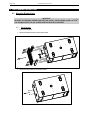
Front Panel
Menu A and Menu B buttons
16 characters by 2 lines display
Select Wheel & Enter button ()
IN Clip – DSP Clip red LED’s
Speaker Protection yellow LED for each channel
Individual Mute/Solo buttons and red LED for each channel
Amp. Sense & Peak (green & red) LED’s for each channel
FLASH EPROM
Software updates/upgrades, new system setups, available on www.nexo-sa.com
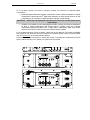
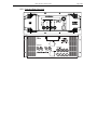
Rear Panel
RS232 connector for serial com
2 x RJ45 connectors
Dimensions & Weight
1U 19" Rack - 230 mm (9") Depth.
4 kg
10.4.2 Front and Rear Panel view
50 - 60Hz 45W
RS232
SENSE INPUT
(from amp terminals)
CAUTION !
To reduce the risk of electric schock, grounding
of the center pin of this plug must be maintained.
+ 4 -
+ 3 -
+ 2 -
+ 1 -
03105sept.04
115 - 230V
MADE IN FRANCE
NX242
NX242 TDcontro
GeoD Passive mode
Crossover 80Hz
NXtension-ES
BALANCED OUTPUTS
FLOATING BALANCED INPUTS
Out
In
In Rx
In Tx
Out Rx
Out Tx
Channel 4
Channel 3
Channel 2
Channel1
B (RIGHT)
A (LEFT)
Page 52/55
RS18 TECHNICAL SPECIFICATIONS
10.5 NXAMP4x1 & NXAMP4x4 Powered Digital TDControllers
10.5.1 Specifications
SPECIFICATIONS
Number of Amplifier Channels
Max Output Voltage (no load)
Max Output Power (8Ω)
NXAMP4x1
4 channels, 2 by 2 bridgeable
4 x 10⁵ V
4 x 600 W
Max Output Power (4Ω)
4 x 900 W
4 x 3300 W
Max Output Power (2Ω)
Power Consumption (Standby)
Power Consumption (Idle)
Power Consumption (1/8 Power)
Analog Input Channels
Frequency Response
Input Impedance
4 x 1300 W
4 x 4000 W
10 W
100 W
1100 W
4 channels In / Out
+/-0.5dB from 10 Hz to 20 kHz
20 W
150 W
3000 W
Max Input Level
Dynamic Range
THD+Noise
Latency Time
FEATURES
Audio Inputs Connectors
Speaker Outputs Connectors
RS232 Port
GPIO Port
DSP Processing
Front Panel
Rear Panel
Power Supply
Dimensions & Weight
NXAMP USER CONTROLS
System Selection
System Setup
Protections (factory defined)
Delay
Input Patching
Output Gain
Volume Control
Save / Recall
Array EQ
Security Mode
Remote Control
STATUS
Green Status
Certification
NXAMP4x4
4 channels, 2 by 2 bridgeable
4 x 200 V
4 x 1900 W
20 kΩ
+28 dBu
105 dB unweighted
Typical 0.1% flat setup
500us on flat setup
4 balanced analogue inputs on XLR3F + links on XLR
4 digital inputs via optional Ethersound Card
4 Speakon outputs with internal power relays for automatic output assignment.
Allows firmware upgrade for software improvement and new speakers setups
5 Global Purpose Inputs and 8 Global Purpose Outputs, software assigned
Two DSP’s 24bits 48bit accumulator 700MIPS
On/off Mains switch, Select Wheel, Menu A and Menu B buttons, 40x2 characters
display, amp protect, stand-by and power LED’s, volume indicators (15 LED’s), Mute
buttons and red LED, output current signal green LED, Speaker protection yellow LED,
amp peak red LED
1 (NXAMP4x1) or 2 (NXAMP4x4) mains sockets, RS232 serial communication connector,
GPIO port, expansion slot for digital audio network extension card, 4 XLR inputs, 4 XLR
links, 4 Speakon NL4.
Dedicated versions for 100-120 V or 220-240 V
NXAMP4x1: 3U 19” Rack – 457mm (18”) Depth – 16.5kg (33lbs) net
NXAMP4x4: 4U 19” Rack – 457mm (18”) Depth – 24.5kg ( 49lbs) net
Allows control across all NEXO range
Within selected range, allows cabinets to be set for:
passive or active;
wideband or cross-over;
cross-over points;
omni or directional modes.
Peak limiters fitted for both selected speaker and amplifier;
Acceleration protection preventing membrane stress
Displacement protection preventing over-excursion
Temperature protection preventing voice-coil damage
Inter-channel regulation
Up to 150m (330ft) in 10cm (4”) steps
Allows any of the inputs to be routed to any output
Global and individual channel gain +/-6dB in 0.5dB steps
Global and individual channel gain –inf to 0dB in 16 variable steps
Stores up to 40 user setups; “On-the-Fly” recalls
LF or HF shelving filters to compensate for arrays quantity dependent behaviour
Password protected for Read-Only or Remote-Only modes
Full Remote Control via Ethersound Digital Network Protocole and ESMonitor software
ROHS, WEEE
UL, SEMKO (CE), CCC, KOREA, TSS, PSE
RS18 TECHNICAL SPECIFICATIONS
10.5.2 Front and Rear Panel view
Page 53/55
Page 54/55
RS18 PARTS & ACCESSORIES LIST
11 RS18 PARTS & ACCESSORIES LIST
11.1 Modules & Control Electronics List
MODEL
DRAWING
RS18 Subwoofer
RS18
NX242-ES4
DESCRIPTION
GeoD Passive mode
Crossover 80Hz
NXAMP4x1
Digital TDController with NX-ES4 Card
Power Digital TDController 4x1300W/2Ω
NXAMP4x4
Power Digital TDController 4x4000W/2Ω
11.2 Accessories List
MODEL
DRAWING
DESCRIPTION
RST-BUMPER18
Main RS18 Bumper
RSTFPLATES18
Rigging plate (pair).
RST-WB18
2 Wheels on wood skids (pair)
RST-DOLLY18
RS18 Dolly (3 RS18 max)
USER NOTES
12 USER NOTES
France
Nexo S.A.
Parc d’Activité de la Dame Jeanne
F-60128 PLAILLY
Tel: +33 3 44 99 00 70
Fax: +33 3 44 99 00 30
E-mail: [email protected]
www.nexo-sa.com
Page 55/55