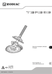
1
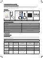
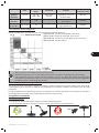
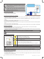
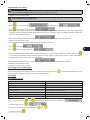
Instructions for installation and use
English
More languages on:
www.zodiac-poolcare.com
H0434900.A - 2013/11
EN
• Read this notice carefully before installing, maintaining or repairing this appliance!
• The symbol
indicates important information that you must take into account to avoid the risk
of injury or damage to the appliance.
• The symbol
indicates useful information as an indication.
Warning
• As part of a continuous improvement process our products may be modified without prior notice.
• Exclusive use: pool water pH regulation system (not to be used for any other purpose).
• The appliance must be installed by a qualified technician, in compliance with the manufacturer’s
instructions and in compliance with current local standards. The installer is responsible for the
installation of the appliance and compliance with local regulations in matters of installation. Under
no circumstances can the manufacturer be held liable in the event that applicable local installation
standards are not respected.
• It is important that this appliance be handled by skilled and apt persons (physically and mentally)
having received the instructions for use beforehand (by reading these instructions). All persons not
meeting these criteria must not approach the appliance in order to avoid exposure to dangerous
elements.
• If the appliance suffers a malfunction: do not try to repair the appliance yourself, contact your
installer.
• Before working on the appliance, make sure that it, and any equipment connected to it, is powered
off.
• Before any connections, make sure that the voltage indicated on the plate on the appliance
corresponds to the mains voltage.
• Eliminating or shunting any safety devices will automatically void the warranty, as will the
replacement of parts using parts not originating from our warehouses.
• Incorrect installation may cause damage to property or serious injuries (possibly causing death).
• Keep the appliance out of the reach of children.
• Do not use hydrochloric acid, use a specific pH correcting product recommended by your pool
specialist.
1
H0434900.A - EN - 2013-11
Contents
1. Information before installing ......................................................................................................... 3
1.1 General delivery terms and conditions ............................................................................................... 3
1.2 Contents ........................................................................................................................................................ 3
1.3 Technical specifications ............................................................................................................................ 3
2. Installation ................................................................................................................................................... 3
2.1 Preparing the pool ..................................................................................................................................... 3
2.2 Hydraulic connections............................................................................................................................... 4
2.3 Electric connections ................................................................................................................................... 5
3. Use ..................................................................................................................................................................... 5
3.1 Control box presentation ......................................................................................................................... 5
3.2 Checks before commissioning ................................................................................................................ 5
3.3 Calibrating the sensor ............................................................................................................................... 6
3.4 Priming the peristaltic pump .................................................................................................................. 6
EN
3.5 Settings .......................................................................................................................................................... 6
4. Maintenance .............................................................................................................................................. 8
4.1 Changing the peristaltic tube.................................................................................................................. 8
4.2 Wintering ...................................................................................................................................................... 9
5. Troubleshooting ....................................................................................................................................... 9
5.1 Display of the regulator ............................................................................................................................ 9
5.2 Appliance malfunctions............................................................................................................................ 9
6. Registering the product .................................................................................................................... 10
Available in the appendices at the end of this instructions leaflet:
• Electric diagram
• Dimensions
• Description
• EC declaration of compliance
H0434900.A - EN - 2013-11
2
1. Information before installing
1.1 General delivery terms and conditions
All equipment, even postage and packing paid, travels at the risks and perils of the recipient. The latter must make
written reserves on the transporter’s delivery documents if damage during transport is discovered (confirmed by
registered letter to the transporter within 48 hours).
1.2 Contents
x1
x1
x1
x1
x1
x1
1.3 Technical specifications
Power supply voltage
Electric output
230Vac-50Hz
9W
Protection index
Maximum peristaltic pump flow
Maximum counter pressure at release point
Correction
pH sensor tolerance
Measurement scale
pH sensor response time
IP65
1.5L/hr
1.5 bar
acid or basic
5 bar / 60 °C / maximum water speed: 2m/s
0.0 - 14.0 pH (± 0.1 pH)
< 15 seconds
2. Installation
2.1 Preparing the pool
2.1.1 Water balance
It is essential that the pool water balance is controlled and adjusted before installing the appliance. Making sure pool
water balance is correct from the start will reduce the likelihood of problems occurring during the first days of operation
or during the pool usage season.
Even though it is an automatic regulation system, it is essential to carry out regular water analyses to check the
water balance parameters.
3
Unit
Recommended
values
pH
/
7.2 – 7.4
Free Chlorine
mg/L or ppm
0.5 – 2
TA
(Total
Alkalinity or
Buffer effect)
°f (ppm)
8 – 15
(80 – 150)
To increase
Test frequency
(during the
season)
To lower
Use the device in
Use the device in ‘acid’
‘alkaline’ dosage mode
dosage mode and/or
and/or increase set point
lower the set point
Add chlorine (manually
Stop the release or
or using automated
production of chlorine
system)
Add alkalinity corrector
(Alca+ or TAC+)
Add hydrochloric acid
Weekly
Weekly
Monthly
H0434900.A - EN - 2013-11
Unit
CH
(Calcium
°f (ppm)
hardness)
Cyanuric acid
mg/L or ppm
(stabiliser)
Metals
mg/L or ppm
(Cu, Fe, Mn…)
Recommended
values
To increase
10 – 30
(100 – 300)
Add calcium
chloride
< 30
/
±0
/
To lower
Add a scale sequestering
agent (Calci-) or run a
decarbonation
Partially empty the pool
then refill it
Add metal sequestering
agent (Metal Free)
Test frequency
(during the season)
Monthly
Quarterly
Quarterly
2.1.2 Appliance release programme
Example: 4 cycles with a set point at 7.4 pH and acid regulation (standard alkalinity):
• pH ≥ 7,55: 20% injection (2 mn) & 80% pause (8 mn)
• pH ≥ 7,7: 50% injection (5 mn) & 50 % pause (5 mn)
• pH ≥ 7,85: 75% injection (7 mn 30 s) & 25% pause (2 mn 30 s)
• pH < 7,9: 100% injection (10 mn)
EN
•
•
•
•
This is inverted of course when a basic dosage is selected.
Active chlorine is more efficient with the correct pH level.
Maximum release rate is 1.5 L/h This dosage ensures that is set point is reached quickly and accurately.
This proportional release is cyclical and cycle duration is 10 mn. The doses will change according to the
distribution of release times and pauses. The proportionality adjusts automatically and the balancing between
the different doses is made using 0.15 pH steps.
2.1.3 Adjusting dosage according to alkalinity
The pH level of water is potentially unstable. Its stability is governed by the level of water alkalinity (also called TA for
‘‘Total alkalinity’’). If the TA is low (< 100ppm), the pH will become potentially unstable and conversely if the TA is high
(>150 ppm).
In order to always achieve optimal water balance, the appliance has a feature that allows users to adjust the quantity of
correcting product potentially released depending on the water TA (see § 3.5.4)
2.2 Hydraulic connections
2.2.1 Sensor location
•
•
The pH sensor must be placed after the filter and before the heating system,
It must be placed vertically or sloping at a maximum of 45°, it should never point downwards.
H0434900.A - EN - 2013-11
4
•
The sensor must be installed at more than 30 cm before or
after a piping bend. Use the optional POD kit if necessary.
Failing to follow this positioning can lead to incorrect or
unstable measurements.
The tip of the pH sensor must not be in contact with the pipe.
Do NOT install a pH sensor before the filtering pump or
between the pump and the filter. This would cause random
readings and a shortened service life.
•
•
2.2.2 Injection point location
•
Injection must be the last element on the pool circuit, after any
heating and water treatment systems.
2.2.3 Sensor and injection point installation
•
•
There must be at least 0.6 metre between the sensor and the point of injection. If this is not possible, use the POD kit
available as an option or a check valve.
Fixture collars/saddle clamps (or the POD kit) must be installed on rigid Ø50 PVC pipes. A Ø63 adapter is available as an
option.
The POD kit is recommended if a Redox regulation (chlorine) has also been fitted.
Maximum pressure must not exceed 1.5 bar.
Drill a hole with a diameter between 16 and 22 mm on the pipe at the selected locations for the sensor and the injection
point.
Then install the fixture collars/saddle clamps.
Use the Teflon tape to ensure that the threads on the sensor holder, the injection valve, and its adapter are watertight.
•
•
•
•
•
2.3 Electric connections
•
•
Using the supplied fixture kit, install the control box on a rigid, vertical surface in an easy to access location.
Connect the power supply cable to a 230Vac mains outlet.
Connected the bared wire to couple the filtering pump to the filtering pump 230Vac contactor using a relay to avoid any
voltage returns when the pump is stopped.
•
Only power on the appliance once all connections (electric and hydraulic) are complete.
3. Use
3.1 Control box presentation
Activating the sensor calibration mode (press for 5 seconds)
Validate choice in the «Settings» menu
Cancel the «OFA» over feed safety system
View the set point value (press for 5 seconds)
Exit the «Settings» menu
Scroll up or down through the «Settings» menu
Activate the «Priming» function (press the UP button for a long time)
0-1
General switch to power the appliance on and off
Thanks to its double electrical supply, the appliance is always powered on, even if filtering is stopped, making it
possible to display the water pH level at all times. The sensor can also be calibrated when filtering is stopped.
The appliance can be powered off at all times using the 0-1 switch on the side of the appliance.
3.2 Checks before commissioning
•
The suction tube must be immersed in the disinfectant product container with the suction cane and is connected to the
peristaltic pump (left side).
• The injection tube is connected on one side to the peristaltic pump (right side) and on the other side to the pool
discharge pipe via the injection valve.
• The peristaltic pump cover must be refitted using its fixing screw.
5
H0434900.A - EN - 2013-11
3.3 Calibrating the sensor
For the appliance to operate accurately and reliably, the pH sensor must be calibrated regularly (on installation,
on re commissioning after wintering, and every 2 months when in use).
Rinse the tip of the pH sensor with clean water using the supplied bottle of H²O filled with tap water.
Shake it to remove excess water.
•
•
Don’t wipe the sensor or touch its tip!
•
Immerse the sensor in the bottle containing the pH7 buffering solution.
•
Press
•
•
•
Press
, the progress bar is displayed:
,
After about 30 seconds, the pH sensor reliability is displayed as a percentage. If the value is above 25%, continue the
calibration process, otherwise power off the appliance using the 0-1 button, replace the buffering solution and/or the
pH sensor, then restart calibration.
•
Press
to display
Press
to display the progress bar:
•
•
,
•
•
•
is displayed, then
Rinse the tip of the pH sensor with clean water using the supplied bottle of H²O filled with tap water.
Shake it to remove excess water.
Immerse the sensor in the bottle containing the pH 4 buffering solution.
•
•
for 5 seconds until
,
EN
,
After about 30 seconds, the pH sensor reliability is displayed as a percentage. If the value is above 25%, press
to complete the calibration process, otherwise power off the appliance using the 0-1 button, replace the buffering
solution and/or the pH sensor, then restart calibration.
Rinse the tip of the pH sensor with clean water using the supplied bottle of H²O filled with tap water.
Shake it to remove excess water.
Fit the sensor back onto its holder.
3.4 Priming the peristaltic pump
The peristaltic pump is self-priming. However, it can be run manually by pressing
to inject corrector product as long as the key is kept pressed down.
. The peristaltic pump will then run
3.5 Settings
3.5.1 «Settings» menu
Menu
Default Settings
Language
pH set point
Dosage
Alkalinity level
«OFA» Over Feed Alarm
Calibration
Filtering operation detection
French
7.4
Acid
Standard (100 < TAC < 150 ppm)
4 hours
Activated 2 points (pH7 and pH4)
Activated «On»
• Press simultaneously on
and
• To exit the menu, press
:
for 5 seconds when the appliance is powered on:
• Select “Yes” or “No” using the following keys
• Confirm by pressing
.
H0434900.A - EN - 2013-11
and
,
6
3.5.2 «Language» Menu
The interface has six available languages:
• EN = English,
• FR = French,
• ES = Spanish,
• DE = German,
• IT = Italian,
• NL = Dutch.
3.5.3 «Set point» menu
It is used to define the set point for the desired pH level.
2 methods:
• see §3.5.1.
Or:
• Press
when the appliance is running:
• Keep
pressed and adjust the set point using keys
,
and
.
• Release the
key to exit.
3.5.4 «Dosage» menu
It is used to select the type of corrector product to be injected (acid or basic dosage).
3.5.4 «Alkalinity» menu
It is used to select the level of alkalinity for the pool water: standard (100 < TA < 150 ppm), high (TA > 150 ppm) or low (TA
< 100 ppm).
3.5.5 «OFA Time» Menu
The appliance is fitted with a safety system to avoid all risks of correction product overdoses if a problem occurs with
the sensor for example. This safety mechanism, which is called «OFA» (= Over Feed Alarm), pauses the appliance if it has
not reached the set point within a given time limit. A high value is strongly recommended to avoid any unplanned and/
or unjustified triggering (a setting in excess of 4 hours is suitable for large pools and/or highly used pools or with high
alkalinity levels).
7
H0434900.A - EN - 2013-11
The over feed safety operates in two main steps:
•
flashes after 75% of the programmed time without having reached the set point
•
is displayed when the time is up. The appliance then switches to safety mode.
If filtering stops and restarts (=daily cycles) while the appliance is in «Stop OFA» status, the appliance will activate an «OFA
Test» mode for 1 hour to ensure that the measurements from the sensor are correct.
On completion of this «OFA Test» mode:
- if the set point has been reached = the appliance remains in normal mode
- if the set point has not been reached: the appliance switches to «OFA Alarm» mode with injection of corrector product.
- if the set point has still not been reached after the «OFA Alarm» mode is complete (=25% of total OFA set time), the
appliance switches to «OFA Stop» safety mode and will remain in this state until a human intervention.
To acquit this safety measure and restart the appliance, press the
and calibrated.
key. First check that the sensor is in good condition
Special over feed safety function:
In order to prevent false alarms just after the appliance is installed, the over feed safety can be deactivated for 24 or 48
hours:
•
•
Press
,
and
at the same time to deactivate the safety system for 24 hours
Press
,
and
at the same time to deactivate the safety system for 48 hours
3.5.6 «Calibration» menu
It is possible to perform calibration in a single step for pH7 (quicker but the measurements will be less reliable in time), or
to remove this function (we advise strongly against this, except in the case of pools with a maintenance contract).
3.5.7 «Filtering» menu
This appliance is fitted with a double electric power supply making it possible to keep the appliance switched on to
perform pH sensor calibration when filtering is not operational. This function can however, be deactivated in the case of a
different electrical connection (only carried out by a professional).
The appliance will no longer take filtering status into consideration and may inject corrector product when
there is no flow in the piping. This deactivation is only valid if the mains power cable is coupled to the filtering.
3.5.8 Resetting the appliance
All the factory settings can be restored.
• Turn off the appliance
• Turn the appliance back on while pressing simultaneously
•
Select «Yes» or «No» using the
and
and
:
keys, keys, then confirm by pressing
.
4. Maintenance
4.1 Changing the peristaltic tube
•
•
•
•
•
•
•
•
•
Remove the peristaltic pump cover,
Place the roller holder at «10:20» by turning it clockwise,
Completely free the left fitting by keeping it stretched towards
the outside,
Then turn the roller holder clockwise to free the tube up to
the right fitting.
Make sure the roller holder is in the 10:20 position.
Insert the left fitting of the new peristaltic tube in its housing.
Then pass the tube into the roller holder guide.
Turn the roller holder clockwise and accompany the tube up to the right fitting.
Refit the peristaltic pump cover.
H0434900.A - EN - 2013-11
8
EN
4.2 Wintering
•
During wintering it is recommended to rinse the peristaltic tube using clean water by carrying out
manual priming (see §3.4).
Then place the roller holder at 6 o’clock to facilitate restarting.
Remove the pH sensor from its holder and store it in its original bottle, or in a container filled with tap
water.
Close off the sensor holder if necessary.
•
•
•
Always keep the sensor in water and protected from freezing.
5. Troubleshooting
5.1 Display of the regulator
Message
«Level»
«OFA Alarm»
Possible causes
• Protector product container
empty
• Floater blocked
• Level sensor short circuited.
First step in the over feed safety
system activated (time > 75%)
Solutions
Replace the corrector product container
Check that the white floater on the suction cane is in working
order
Change the suction cane
•
•
•
•
•
«OFA Stop»
Second step in the over feed safety
system activated (time = 100%)
•
Press
to stop the alarm
Check the sensor and/or the pool pH level
Wait for the end of the procedure (1 hour) then check the
sensor and/or the pool pH level.
•
«OFA Check»
«Flow»
«Error»
«Error
Parameter»
Press
to stop the alarm
Check the sensor and/or the pool pH level
pH sensor measurement test when
the «OFA Stop» was activated
during a previous filtering cycle.
• Filtering stopped
• Incorrect connection
• Used Buffer solution(s)
• pH sensor dirty
• Defective pH sensor
Setting error
•
•
Start and/or check the filtering
Check the electric connections
Replace the buffer solution(s)
Clean the pH sensor using a 10% HCl solution
Replace the pH sensor
•
•
•
•
•
•
Press
to cancel the fault
Replace the electronic card
5.2 Appliance malfunctions
Malfunction
Possible causes
The appliance
Cable problem and/or BNC •
always displays a pH connector problem
value close to 7.0
•
The appliance
always displays an
unsuitable value
or the measure is
constantly unstable
•
•
•
•
•
9
pH sensor connection cable is
damaged
There is an air bubble in the
pH sensor bulb
The pH sensor is worn
The pH sensor cable is too
close to an electric cable
causing disturbances
The sensor is not correctly
fitted on the piping.
•
•
•
•
•
Solutions
Check that the connection between the sensor and the
control box is not short circuited (between the cable’s
central core and the external shielding)
Check that there is no humidity and/or condensation at the
BNC connector level
Check the cable and/or the BNC connector
Position the pH sensor vertically and shake gently so that
the air bubble rises to the top (sensor must be mounted
vertically or at a 45° angle maximum, seer §2.4)
Replace the pH sensor
Reduce the distance between the appliance and the sensor
Place the sensor in a more suitable location (see §2.2.1)
H0434900.A - EN - 2013-11
Malfunction
Possible causes
Buffer solution defective
•
Problem on porous element •
of sensor and/or deposits
pH sensor is worn
•
Solutions
•
Ensure that the solution used is pH7 or pH4
•
Check the pH of buffering solution using an electronic pH
tester
pH7 and/or
•
Use new pH7 and/or pH4 buffering solution
pH4 calibration
• Restart calibration
impossible (error
• Check that the bulb on the pH sensor is not damaged or has
message)
not dried up while out of the water.
or
• As a last resort, clean it by leaving sensor in a solution of
pH sensor reliability
10% hydrochloric acid for a few hours.
< 25%
• Check that the porous element on the sensor is in good
condition (clean with acid solution).
• Replace the pH sensor
Slow response of pH pH sensor is charged electrosta- Do not use a cloth or paper to wipe the sensor, shake it gently
sensor
tically
6. Registering the product
Register your product on our website:
- be the first to be informed of new Zodiac products and special offers,
- help us to continuously improve our product quality.
Australia – New Zealand
Europe, South Africa & Rest of the World
H0434900.A - EN - 2013-11
www.zodiac.com.au
www.zodiac-poolcare.com
EN
10
Electric diagram
Dimensions
1
H0434900.A - EN - 2013-10
Description
1
2
3
4
5
6
7
8
Peristaltic pump
Main switch
BNC connector socket for pH sensor
Cable gland for direct coupling with filtering system
Connector for suction tube
Connector for injection/release tube
Gland for suction cane cable
Gland for 230Vac/50Hz power supply cable
H0434900.A - EN - 2013-10
2
Zodiac Pool Care Europe - BP 90023 - 49180 St Barthélémy d’Anjou cedex - S.A.S.U. au capital de 517 200 € / SIREN 395 068 679 / RCS PARIS
www.zodiac-poolcare.com
Pour plus de renseignements, merci de contacter votre revendeur.
For further information, please contact your retailer.
ZODIAC® is a registered trademark of Zodiac International, S.A.S.U., used under license.
Votre revendeur / your retailer