1
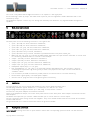
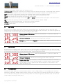
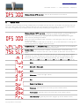
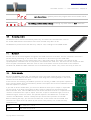
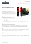
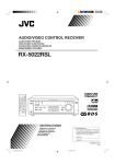
www.soundskulptor.com
Document revision 1.1 – Last modification : 20/10/14
Sound Skulptor MC624 User manual
1.
Overview
The MC624 lets you select one out of six stereo line level audio sources, adjust the level and route it to one out of four
stereo amplified monitor pairs.
The level can be set in very accurate1dB increments.
It gives you the possibility to listen to normal stereo, right only, left only, left + right (mono), left & inverted right, left –
right (difference), dimmed and mute.
Each input can be configured for balanced or unbalanced, -10dBV or +4dBu level and an offset can be added if needed
to correct input level differences.
Each output can be configured for balanced or unbalanced and an offset can be added if needed to correct output level
differences. Output 4 can be set as a Sub output.
An infra-red detector allows controlling the MC624 from an ordinary TV remote.
Several units can be linked together for surround. One unit is the master and controls the other units.
2.
Design considerations
The design objective has been to put as little electronics as possible between input and output. The total passive
approach was ruled out because of the stress it puts on the audio sources, increasing distortion, when you want to
achieve a low enough output impedance, necessary for the noise immunity. So we opted for a unity gain buffer, optionally
switch-able to provide the12dB of gain, necessary for the semi-pro -10dBV compatibility. The buffer used is one the
best op-amps available today (spec'ed distortion at 0.00008%). This buffer is the sole active component in the signal
path.
Copyright ©2014 SoundSkulptor
www.soundskulptor.com
Document revision 1.1 – Last modification : 20/10/14
The circuit is fully differential throughout and there is no capacitor in the signal path.
All the switching is done by relays. The buffer feeds a passive precision logarithmic ladder attenuator that is also
switched by relays.
The headphone amplifier is also a very nice design with extremely low distortion, very high bandwidth and high drive
capability.
3.
Back panel connections
The back panel carries the following connectors, from right to left:
•
•
•
•
•
•
•
•
•
•
•
•
•
•
•
•
4.
input 1 (2x XLR), line level, balanced or unbalanced,
input 2 (2x XLR), line level, balanced or unbalanced,
input 3 (2x 1/4” jack), line level, balanced or unbalanced,
input 4 (2x 1/4” jack), line level, balanced or unbalanced,
input 5 (2x RCA cinch), line level, unbalanced,
input 6 (2x RCA cinch), line level, unbalanced, paralleled with the front panel 3.5mm jack,
Meter out (2x 1/4” jack): is a line level (+4dBu) output taken after the input selector and buffer. It can be used
for connecting a buffered meter or used as a record output.
output 1 (2x XLR), line level, balanced or unbalanced,
output 2 (2x XLR), line level, balanced or unbalanced,
output 3 (2x 1/4” jack), line level, balanced or unbalanced,
output 4 (2x 1/4” jack), line level, balanced or unbalanced,
Headphone output (Top), (1x 1/4” jack),
Dim input (Bottom), (1x 1/4” jack): is an input that activates the DIM function. The activation is done by
connecting the tip and the ring of the jack by a switch. The purpose of this input is to be connected to a
“Talkback” switch.
Link connectors (2x USB connected in parallel) used to link several units for surround monitoring.
DC-IN needs a good quality 12V-25W power adapter
Ground: Use for tying the case to the general ground if necessary.
Installation
Connect inputs to your source signals and outputs to your various amplified monitor pairs.
The XLR plugs follow the typical scheme: Pin 1 = Shield, Pin 2 = Hot, Pin 3 = Cold.
The jack plugs follow the typical scheme: Tip = Hot, Ring = Cold, Sleeve = Shield.
Connect the 12V power adapter to the DC-IN connector.
There are 2 headphones output, one on the front panel and one on the back panel. These outputs are derived from the
same amplifier.
The Meter-out output lets you connect a buffered meter pair or can be used as a record output.
The link connectors allows linking several units together. They use a standard USB connector but cannot be connected
to other USB devices.
The ground thumb nut is used to connect the chassis to ground if needed.
5.
Front panel commands
INPUT SELECT Pressing one of the six push switches selects the corresponding input and sends it to the selected
Copyright ©2014 SoundSkulptor
www.soundskulptor.com
Document revision 1.1 – Last modification : 20/10/14
output and to the Meter Output. Inputs are mutually exclusive.
OUTPUT SELECT Pressing one of the four push switches sends the selected input to the corresponding output. Outputs
are exclusive except output 4 which can be set as a SUB output and activated in addition to one of the first three.
MUTE Turns off the monitor output signal (but not the Meter Output neither the headphone output).
L/R Mutes the left and right channels alternatively. Unmuting is done by pressing the MUTE switch.
MONO Sums the left and right channels and sends the result to both.
DIFF Inverts the phase of the right channel. When DIFF and MONO are both activated, the output is the difference leftright.
DIM attenuates the output by an amount of dB defined in “Functions Setup” (default: -20dB).
LEVEL Sets the monitoring output level. It is also used to set-up parameters.
PHONES Sets the phone level, independent of the monitoring level.
O1 switch Power switch.
6.
Input setup
A long press on an INPUT switch starts setup of the corresponding input. The LED blinks when you enter the setup
mode. There are 3 settings that you can cycle through by pressing again on the same switch. The values are adjusted by
the LEVEL knob. You leave the setup mode by pressing any other switch.
Blinking between OFS and value : Adds an offset between –12 and +12 dB to the
input signal.
Balanced / unbalanced : Must be set accordingly to the input type.
Low gain (for +4dBu input) / High gain (for -10dBV input) : Must be set accordingly to
the input level.
7.
Output setup
A long press on an OUTPUT switch starts setup of the corresponding output. The LED blinks when you enter the setup
mode. There are 2 settings (3 for output 4) that you can cycle through by pressing again on the same switch. The values
are adjusted by the LEVEL knob. You leave the setup mode by pressing any other switch.
Blinking between OFS and value : Adds an offset between –12 and +12 dB to the
output signal.
Balanced / unbalanced : Must be set accordingly to the monitor input type.
Normal output / Sub (only on output 4) : When set to Sub, the output 4 is switched in
addition to the other (1 to 3) selected output. It is used to switch a sub bass output.
The sub output is wired in parallel to the selected output so it cannot have its own
offset and bal/unb mode.
8.
Functions setup
The functions setup allows you to set an offset for Mono (-12 to +12dB) and Diff (-12 to +24dB) and to define the
attenuation of Dim (0 to -63dB). Initiate setup by a long press on the switch corresponding to the function you want to
set. The LED starts blinking when you enter the setup mode. The values are adjusted by the LEVEL knob. You leave the
setup mode by pressing any other switch.
Copyright ©2014 SoundSkulptor
www.soundskulptor.com
Document revision 1.1 – Last modification : 20/10/14
Blinking between OFS and value : Set the desired offset to the function.
9.
System setup
Initiate the system setup by pressing simultaneously on the Mute and Dim switches. The 2 LED's start blinking when you
enter the setup mode. There are 5 settings that you can cycle through by pressing again on one of the same switches.
The values are adjusted by the LEVEL knob. You leave the setup mode by pressing any other switch.
Blinking between “OFS” and value : Subtracts an offset between 0 and 63 dB to the
displayed value. This is only cosmetic and has no effect on the output level.
When set to -63 (default) the displayed value represents the attenuation and goes
from -63 to 0, 0 being the loudest.
When set to 0 the displayed value represents a level that goes from 0 to +63, +63
being the loudest.
You can set a different value that will show 0 for your preferred/reference listening level
and display positive or negative values from there.
Headphone low gain / headphone high gain : Sets two different gains on the headphone
amplifier to better match different headphone sensitivities.
Master / Slave : The normal mode is Master. The Slave mode is used when using
several MC624 for surround. One unit is set to master, all the other units are set to
Slave.
Remote control learning mode. The LEVEL knob lets you step through all the available
commands. For each command you must press the desired TV remote button. When
the new IR code is learned, the display stops blinking. The available commands are:
in1(input 1), in2(input 2), in3(input 3), in4(input 4), in5(input 5), in6(input 6),
Mute,
Mute left – Mute right,
Mono,
Difference : inverts the right channel,
Dim,
Output 1 to Output 4,
Volume up : generally tied to the level up of the remote control,
Volume down : generally tied to the level down of the remote control,
input channel up : generally tied to the program up of the remote control,
Copyright ©2014 SoundSkulptor
www.soundskulptor.com
Document revision 1.1 – Last modification : 20/10/14
input channel down : generally tied to the program down of the remote control.
Do nothing / restore factory settings : Pressing any switch when on CLR, resets the
device memory to the factory setting.
10.
IR remote control
The MC624 can be remote controlled by almost any TV remote. We recommend the “One for
All” model 7960 because we tested it and it feels solid but many other will do.
The MC624 is preset to work with the Sony 1825 or 1651 settings on the 7960 remote.
11.
Surround
Several units can be linked together through the dual USB connector at the back. The two connectors are wired in
parallel allowing connecting 2, 3 or more units. Connection is done with a type A-A USB cable.
You must set one master unit and several slave units in the System Setup. The master unit transmits all the
input/output/level commands from its front panel or IR remote to the slave units. The slave units also respond to their
own front panel commands but these are reset as soon as the master receives and forwards a new command.
The Mute L-R, MONO and DIFF commands are not forwarded by the master. They can be set locally on each unit.
12.
Clicks immunity
Because the MC624 passes DC, you might hear some clicks when switching inputs if one of the
sources presents some DC offset on its output. Same thing when switching outputs if one of the
monitors has a DC offset on its input.
If the clicks are too annoying, the PCB has provision for inserting a 100uF-16V bipolar capacitor on
every input and output which will eliminate any offsets. The outputs also receive an additional resistor
when the capacitor is inserted.
If you want to do this modification, you must first determine which input or output is responsible
for the clicking. It will keep clicking when all other inputs (or outputs) are disconnected from
external devices. Then, from the table below, find out the reference of the 2 or 4 capacitors and
resistors connected to this input or output. There are 2 caps for a balanced signal, one for an
unbalanced signal, 2 times for stereo. The optional capacitors are labelled Cz1 to Cz36, the
resistors are labelled Rz1 to Rz16. Identify the caps and resistors positions on the PCB.
Before soldering the caps, you must cut the small track, on the solder side of the PCB, that
connects the 2 pads of the cap (shown by red arrows in the picture). Use a small and sharp
cardboard knife.
Input 1
Cz1, Cz2, Cz11, Cz12
Input 2
Cz3, Cz4, Cz13, Cz14
Copyright ©2014 SoundSkulptor
www.soundskulptor.com
Document revision 1.1 – Last modification : 20/10/14
Input 3
Cz5, Cz6, Cz15, Cz16
Input 4
Cz7, Cz8, Cz17, Cz18
Input 5
Cz9, Cz19
Input 6
Cz10, Cz20
Output 1
Cz21, Cz22, Cz29, Cz30, Rz1, Rz2, Rz9, Rz10
Output 2
Cz23, Cz24, Cz31, Cz32, Rz3, Rz4, Rz11, Rz12
Output 3
Cz25, Cz26, Cz33, Cz34, Rz5, Rz6, Rz13, Rz14
Output 4
Cz27, Cz28, Cz35, Cz36, Rz7, Rz8, Rz15, Rz16
Copyright ©2014 SoundSkulptor