1
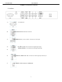
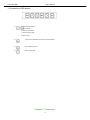
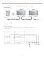
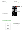
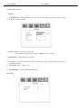
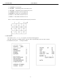
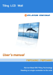
User’s Manual
LCD Video Wall
LCD Video Wall
Universal User’s Manual
Video Wall Model: TL40H1, TL46H1, TL46H2, TL46H3
1
User’s Manual
LCD Video Wall
CONTENT:
Chapter I - Introduction to interface----------------------------------------------------------3
1.1 Introduction to interface-------------------------------------------------------------------------3
1.2 Introduction to OSD buttons-------------------------------------------------------------------4
Chapter II - Connecting -----------------------------------------------------------------------------5
2.1Control video wall through RS232------------------------------------------------------------5
2.2 Display DVI Signal-------------------------------------------------------------------------------5
Chapter III - Introduction to Remote Control and Signal Input ----------------6
3.1 Introduction to Remote Control--- ------------------------------------------------------------6
3.2 Instruction to signal input selection-----------------------------------------------------------6
3.3 Instruction to MENU------------------------------------------------------------------------------7
3.4 Set board ID----------------------------------------------------------------------------------------9
2
User’s Manual
LCD Video Wall
Chapter I Introduction to interface
1.1 Interface :
A.
AC IN: AC POWER IN
B.
RS232 INPUT/OUTPUT: RS232C serial Port
C.
BNC/RGB/HV IN: (R, G, B, H, V)BNC Connector for VGA signal
D.
DVI (DVI –D) IN: DVI-D Connector for digital signal input;
VGA2(D-SUB) IN: VGA Connector for analogue signal input
E.
E.
BNC/VIDEO IN, VIDEO1 OUT: BNC Connector for VIDO signal input and out put.
F.
KEY BOARD: RJ45 connector for OSD board
3
User’s Manual
LCD Video Wall
1.2 Introduction to OSD buttons:
: Left and Right buttons
1)
a. adjust volume
b. select in OSD menu.
c. select in signals input
d. adjust values
2)
:
3)
:
Open signals input list
4)
:
Select signal input.
Open/Close OSD Menu or Return to Previous Menu
Chapter II Connecting
4
User’s Manual
LCD Video Wall
2.1 Control monitors through RS232:
Video wall monitors can be controlled by computer through RS232 cable. There are two RS232 connectors on
the monitor (one for signals input, the other for signals output). Every monitor needs a separate ID number to
manage through RS232.
2.2 Display DVI Signal
Multiple video wall monitors can be connected to the splitter box. This takes the input signal and displays it on
the monitors connected.
5
User’s Manual
LCD Video Wall
Chapter III Introduction to Remote Control and Signal Input
3.1 Introduction to Remote Control:
Power
MODE:
Select signal input
Navigation Butt ons:
Press these but tons to select
preference and MENU for
confirmation.
3.2 Instruction to signal input selection:
Press MODE button to enter signals input list and use navigation buttons to make a choice.
1. PC: analogue signal from computer
2. DVI:digital signal from computer
3. AV1 : VIDEO signal input 1
4. AV2: VIDEO signal input 2
6
User’s Manual
LCD Video Wall
3.3 Introduction to menu:
■Picture:
Press “MENU”button, following picture will show on the screen. Press“▲, ▼” to choose the item you want and
press “◀ , ▶” to change parameters.
1) Contrast:Adjust the contrast ratio of the picture.
Press “◀, ▶” to change parameters and press “MENU” to save your settings.
2) BRIGHTNESS:Change luminance of the picture.
3) Color mode:You can choose different Color mode, according to your prefer. It has four mode: USER, COLD,
WARM, STANDRAD.
4) Aspect ration mode :Normal, Center
5) PICTURE MODE: USER STANDARD SPORT SOF
■SETTING:
7
User’s Manual
LCD Video Wall
1) TEMPERATURE:Actual temperature insight machine.
2) FAN ACTIVE:The user can set an optimum temperature. When the actual temperature is higher than the
set temperature, the fan will automatically run; when temperature inside the machine is lower than the set
temperature, fan will shut down automatically.
3) RESET:recall the default settings.
■ OSD:
1) OSD LANGUAGE:Press “◀, ▶” to change the kind of language. You can choose English or Chinese.
2) MENU Display configuration : horizontal position, vertical position, display time, transparence.
3) Digital video wall adjust:Stretch picture towards left /right/up/down. If the picture can’t be perfectly spliced by
software, you can use this function to adjust the screen.
■ ADVANCE:
Press “◀, ▶” to change parameters,Press “MENU” button to save settings
8
User’s Manual
LCD Video Wall
1) CLOCKER:Set current time
2) ON TIEM: Automatically power on as the time you set.
3) OFF TIME: Automatically power off as the time you set.
4) CURRENT X: Number of X on the digital wall
5) CURRENT Y: Number of Y on the digital wall
6) TOTAL X: Total number of monitor on X axis
7) TOTAL Y: Total number of monitor on Y axis
Take 3×3 wall for example,The following sketch map for your reference.
3.4 Set board ID:
Press “MENU” and “1”, “8”, “4”, “2” in sequence. You will see following picture.
Press “▼” and let halo on “OTHER OPTION”, then press “▶” to open subsidiary menu. Press “▼” to let halo
on “BOARD ID”, then press “ , ”to change ID number.
9