1
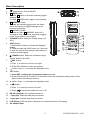
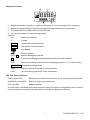
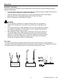
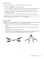
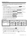
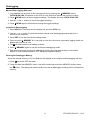
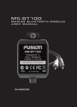
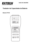
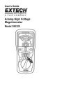
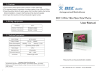
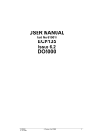
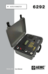
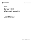
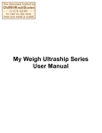
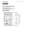
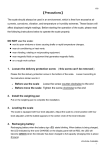
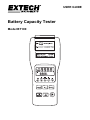
USER GUIDE Battery Capacity Tester Model BT100 Introduction Thank you for selecting the Extech Model BT100. The Battery Tester is designed for measuring the internal resistance and output voltage of batteries including lead storage cells, nickel-cadmium batteries, lithium-ion batteries, and nickel-metal hydride batteries. This device is shipped fully tested and calibrated and, with proper use, will provide years of reliable service. Please visit the Extech Instruments website (www.extech.com) to check for the latest version of this User Guide. Features Accurate results are achieved using a four-terminal measurement method that eliminates lead and contact resistance. 1kHz test current with up to 10µΩ resistance resolution. Dual display simultaneously indicates the internal resistance and the battery voltage. Comparator function with storage of up to 99 sets of resistance and voltage data for battery deterioration characterization. Pin type and alligator type 4-terminal Kelvin leads for quick and accurate resistance measurements. Memory capacity to store up to 999 (manual datalogging) or 9600 (automatic datalogging) data points. Supplied RS232 PC port and Windows compatible software. Safety International Safety Symbols This symbol, adjacent to another symbol or terminal, indicates the user must refer to the manual for further information. This symbol, adjacent to a terminal, indicates that, under normal use, hazardous voltages may be present Double insulation 2 BT100-EU-EN V3.0 8/13 Meter Description 1. Power button: Power ON/OFF 2. R READ button: Press R button to show the manually logged readings. Press R READ button again to stop reading. 3. M MEMORY button: Under the manual logging mode, the tester stores a single set of logged readings to the memory by pressing M MEMORY button. Press and hold M MEMORY button for 2 seconds to enter continuous (automatic) logging mode. Press again to stop logging. 4. V-RANGE button: Select the voltage range. (4V, 40V) 5. HOLD button: Press HOLD to freeze or unfreeze the displayed reading. Press and hold the HOLD button for 2 seconds to enter the interval time (sample rate) setting for continuous data logging. 6. Ω - RANGE button: Select the resistance range. (40mΩ, 400mΩ, 4Ω, 40Ω) 7. REL button: Press to move the cursor to the right. Press REL (Relative) to zero the reading. 8. button: Press to increase the displayed value. 9. SET button: Press SET to switch the comparator mode on or off. Press and hold the SET button for 2 seconds to enter the comparator-setting mode. Press again to store the setting in memory. 10. button: Press to decrease the displayed value. 11. Button: Press to move the cursor to the left. Press to switch the audible tone on or off. 12. RS-232 connector: PC interface connector. 13. – Input jack: Black test lead plug connection. 14. + Input jack: Red test lead plug connection. 15. LCD display (LED test status indicators are located below the LCD display) 16. AC adaptor input 3 BT100-EU-EN V3.0 8/13 Display Description 1. Measured resistance reading (or High/Low resistance limit when setting up the comparator) 2. Measured voltage reading (or High/Low voltage limit when setting up the comparator) 3. The comparator set number (there are 99 sets total) 4. The memory location for manually logged data. Symbols: mΩ: Milliohm (resistance) V: Voltage HOLD : Hold function (display freeze) COMP : Comparator function enabled : : DATA R : M: INTV: Low-Battery Beeper enabled Manual datalogging enabled Continuous datalogging enabled (flashes each time data is stored) Interval time setting for the continuous datalogging function. (1 to 255 seconds) COMP.SET : Comparator settings mode HIGH: High limit setting (threshold) for the comparator LOW: Low limit setting (threshold) for the comparator LED Test Status Indicators PASS (green LED): Battery is good (within the tolerances of the comparator’s preset limits) WARNING (yellow LED): Battery is beginning to deteriorate FAIL (red LED): Battery has failed The LED status indications listed above are active when the High/Low comparator limits for internal resistance and the comparator threshold value for voltage are properly configured. 4 BT100-EU-EN V3.0 8/13 Operation Preparation and Safety The following safety information must be observed to ensure maximum personal safety during the operation of this tester. To avoid electric shock when replacing the batteries: Disconnect the test leads from the device under test before attempting to replace the batteries. Check the battery polarity carefully when inserting the batteries. Refer to the battery replacement section (under Maintenance) later in this User Guide. Be sure to dispose of used batteries properly. WARNING Do not attempt to measure DC voltage exceeding 50V. Do not attempt to measure AC voltages; this could result in personal injury or damage to the unit. To avoid personal injury and/or damage to the unit, do not attempt to measure the voltage of a generator. This will result in an AC voltage being applied to the voltage generating output terminals. After measuring a high voltage battery, and before continuing to measure a low voltage battery, short the measurement leads by touching the lead tips together. This will discharge the DC-elimination capacitor (connected across the leads); otherwise a dangerous condition can exist where an excessive voltage may be applied to the low voltage battery. Test Leads Two sets of test leads are supplied with the meter. Both sets provide four (4) terminal Kelvin connections which eliminate lead resistance and probe contact resistance. The application at hand will dictate whether the alligator type or the press-probe type should be used. 5 BT100-EU-EN V3.0 8/13 Testing Procedure Connect the red test lead to the “+” jack and the black test lead to the “-” jack. 1. Press the Power button to switch the tester ON. 2. Use the V-RANGE or Ω-RANGE buttons to select the desired Voltage or Resistance range. 3. Perform a REL Zero adjustment (see next section) each time the range is changed. 4. Connect the red test probe to the positive battery terminal, and the black test probe to the negative battery terminal. 5. Read the battery’s internal resistance and the DC voltage directly on the meter’s display. Note: When the measured DC voltage or battery internal resistance value is over range, “OL” is displayed. When the AC test current faults “- - - -” will be displayed. REL Adjust (ZERO) The REL function zeros the selected range. The reading displayed when the REL button is pressed will be taken as zero and will be used to ‘offset’ subsequent measurements. 1. Short the four (4) probe tips of the red and black test leads as shown in the accompanying diagrams. 2. Press the REL button and the display will show the ‘R’ icon and the resistance and voltage values will zero. 3. Connect the test leads to the battery to be tested. 4. The REL button must be pressed each time the range of the meter is changed, after the test leads are swapped, or after switching between resistance and voltage tests. 6 BT100-EU-EN V3.0 8/13 Comparator (99 sets) The comparator function compares the measured values with preset High and Low limit values for internal resistance and voltage level, and determines the range that the measurement should fall into. Then, according to the following conditions, switches ON the corresponding LED, and sounds an audible alert as shown in the table below for the WARNING and FAIL conditions. Comparator Settings 1. Press and hold the SET button for 2 seconds, the display will show COMP.SET indicating the comparator mode is enabled. 2. Use the or button to change the comparator number from 01 up to 99. 3. Use the V-RANGE or Ω-RANGE button to set the desired voltage and resistance measurement range. 4. Press once, the LOW icon and the left two digits of the low limit resistance will be flashing. (Use the & buttons to select the desired value.) 5. Press once, the right two digits of the low limit resistance will be flashing. (Use the and buttons to select the desired value.) 6. Press once, the HIGH icon and the left two digits of the high limit resistance will be flashing. (Use the and buttons to select the desired value.) 7. Press once, the right two digits of the high limit resistance will be flashing. (Use the and buttons to select the desired value.) 8. Press once, the left two digits of the threshold voltage will be flashing. (Use the and buttons to select the desired value.) 9. Press once, the right two digits of the threshold voltage will be flashing. (Use the and buttons to select the desired value.) 10. Repeat step 2 to step 9 to set the next comparator number. 11. Press SET again to exit the comparator setting mode. Comparator Table Resistance Voltage Voltage Lo Comparison Value Hi Low limit resistance Lo Middle High limit resistance Hi WARNING Beeper WARNING Beeper FAIL Beeper Pass WARNING Beeper FAIL Beeper Comparator Start / Stop Controls 1. Press SET to activate the comparator function, the COMP indication will appear on the display. The comparator will operate once measurements are taken. 2. Use the and buttons to select the desired comparator number. The selected comparator number remains in memory even when the power is switched off. 3. Press to set the audible alert ON, the indication will appear on the display, and the audible tone will sound with a WARNING or FAIL result. Press alert. again to disable the audible 4. Press SET again to switch off the comparator function. 7 BT100-EU-EN V3.0 8/13 Datalogging Manual Data Logging (999 sets) 1. Log readings one at a time to the internal memory by pressing the M MEMORY button. “DATA M NO XXX” will appear on the LCD for one second to indicate the memory location. 2. Press R READ button to review logged readings. The display will show “DATA R NO XXX”. 3. Use the and buttons to scroll the logged readings. 4. Press R READ again to discontinue viewing the logged readings. Continuous Data Logging 1. Press HOLD for 2 seconds and the display will show the INTV icon. 2. Use the or button to select the desired interval time (datalogging sample rate) from 1 second to 255 seconds. 3. Press SET to exit the interval time setting mode. 4. Press and hold M MEMORY for 2 seconds to enter the continuous (automatic) logging mode, the display will show the M icon. 5. The M will flash each time a reading is stored. 6. Press M MEMORY again to exit the continuous datalogging mode. 7. Data stored using the continuous datalogging mode cannot be read directly on the tester’s display, it must be downloaded to a PC using the supplied software. Clearing the Datalogger Memory When the internal memory is full, the Full icon will appear on the display and datalogging will stop. 1. Press to switch OFF the tester. 2. Press and hold the MEMORY button, and while continuing to hold the MEMORY button, press button. The display will show the CLr icon and all datalogged readings will be cleared from the memory. 8 BT100-EU-EN V3.0 8/13 Specifications Resistance measurement method Four (4) terminal Kelvin connections A/D conversion Dual slope Displays Dual LCD for measurements and programming icons Datalogger Sampling rate 1 to 255 seconds (interval time between logged readings) Open-circuit terminal voltage 3.5Vpp max Input over range “OL” display Three (3) test status LEDs Low battery indication display Test current fault detect “- - - -” display Auto power off After approximately 30 minutes Zero (Relative) function Circuit offset voltage is displayed as 0V Hold function Display freezes Audible Alarm function Audible alert for Warning and Failure conditions (can be set ON or OFF) Comparator settings Resistance High/Low limits and Voltage threshold point Number of comparator configurations 99 sets Comparator output Test status LEDs for Pass (green), Warning (yellow), and Fail (red) results (audible tone for Warning and Fail conditions) Resistance Lo IN Hi Lo Warning Warning Fail Hi PASS Warning Fail Voltage Manual Datalogging memory 999 sets can be stored in meter’s internal memory Continuous (automatic) Datalogging 9600 sets can be stored in meter’s internal memory Operating conditions 32 to 104°F (0° to 40°C) 80%RH (non-condensing) Storage conditions 14 to 122°F (-10° to 50°C) 80%RH (non-condensing) Power source Six (6) ‘AA’ 1.5V batteries; Optional 9V AC adaptor Maximum power consumption 1.0VA Maximum continuous operation 7 hours approx. Altitude 2000m max. Dimensions 9.8 x 3.9 x 1.7” (250 x 100 x 45mm) Weight 1.1 lbs. (500g) approx. (including batteries) Accessories Test Leads and batteries Optional equipment AC adaptor (9V output) 9 BT100-EU-EN V3.0 8/13 Electrical Specifications To ensure accuracy the ambient temperature should be 23°C ± 5° with a humidity of 80% RH (maximum) non-condensing. In addition, perform a Zero adjustment after each range change. Resistance measurements Temperature coefficient: (±0.1% rdg ± 0.5digits)/°C Measurement current frequency: 1KHz ± 10% Measurement burden voltage: 1.5mVAC Range Resolution Measurement current 40mΩ 10µΩ 37.5mA approx. 400mΩ 100µΩ 3.75mA approx. 4Ω 1mΩ 375µA approx. 40Ω 10mΩ 37.5µA approx. Accuracy ±(1% reading ± 10digits) Voltage Measurements Temperature coefficient: (±0.1%rdg±0.5digits)/ °C Range Resolution 4V 1mV 40V 10mV Accuracy ±(0.1% reading ± 6digits) Maximum Input Voltage: 50VDC maximum No AC voltage input permitted Maximum between input terminals and ground: 60VDC/AC DANGER Do not exceed the maximum permissible input voltage to the measurement terminals. This could result in personal injury and/or damage to the unit. 10 BT100-EU-EN V3.0 8/13 Maintenance Cleaning 1. Repair or service not covered in this User Guide should be performed by qualified personnel only. 2. Periodically wipe the case with a dry cloth; do not use abrasives or solvents. Battery Check & Replacement The symbol will be displayed when the batteries need replacement. 1. Disconnect the test leads from the meter and from devices under test 2. Switch OFF the power to the tester 3. Open the battery compartment cover with a screw driver 4. Replace the batteries observing polarity 5. Replace and secure the battery cover Battery Safety Reminders Please dispose of batteries responsibly; observe local, state, and federal regulations with regard to battery disposal at all times. Never dispose of batteries in a fire. Batteries may explode or leak. Never mix battery types. Always install new batteries of the same type. 11 BT100-EU-EN V3.0 8/13 PC Software Overview The supplied software combines data acquisition and datalogger functionality. Data acquisition is the process of storing readings on a PC while the meter is connected to the PC and while the meter is actively taking measurements. When Datalogging, the meter is taking and storing readings in its own internal memory while disconnected from the PC. Later, the meter can be connected to the PC to offload the stored data. Installing the Windows Application Program 1. Connect the BT100 to the serial PC port using the supplied interface cable. 2. Place the supplied software CD in the PC CD-ROM drive 3. Wait for “Autorun” to start and follow the on-screen instructions 4. If “Autorun” does not start, click on “Start” then “Run”. Type the drive letter of the CD-ROM and :\VB\Disk1\Setup.exe and click OK (To install the LabVIEW version, type the drive letter and :\LV\installer\Setup.exe and click OK). 5. Change the path if necessary or choose to install the program to its default location. 6. Launch the program by double clicking the program in the location where it was saved during installation. 7. Do not run the supplied software until the meter is properly connected to the PC. Software Operation Click “Start” on the Start menu, click “Programs” and then click on “BatTester” to launch the program. The COM Port screen will appear. Select the COM Port and then click OK. The Battery Tester main screen will appear. On the lower right side of the screen, “COM XX” will appear if a connection has been accomplished (where XX is the COM Port number). “NO COM” will appear if there is no connection. The function of the Main screen icons are: 1. 2. 3. 4. 5. 6. 7. Opens the “Save As” dialog box to save data to a new file. Opens the “Open” dialog box to open a saved file. Opens the “Real Time List” display box for data acquisition mode. Opens the “Real Time Graph” showing voltage and resistance data. Opens the “Real Time Sampling Rate” dialog box for datalogging. Opens the “Data Logger” box and downloads the data from meter to PC. Opens the “Manual Records” box and downloads the data from meter to PC. 12 BT100-EU-EN V3.0 8/13 Data Acquisition Mode In the data acquisition mode, the meter is connected to the computer while taking readings. At the same time the readings are taken, they are displayed and stored on the computer. The readings can be displayed as a List, a Voltage graph or a Resistance graph. Sampling Rate Setting for Data Acquisition Mode The sampling rate for the data acquisition mode can be set from 1 reading per second to 1 reading every 86,400 seconds (1 sample every 24 hours). Note: This sampling rate setting is for the data acquisition mode only. For datalogger mode, the sample rate is set using the meter’s front panel controls as explained in the hardware User Guide supplied with the meter. 13 BT100-EU-EN V3.0 8/13 Datalogger Mode The meter’s internal datalogger memory stores readings in files. Each file is created when a datalogging session is started and then stopped using the MEMORY button (described in the hardware User Guide supplied with the meter). The Datalogger screen lists each file (1, 2, 3, etc.) along with the ohm range, voltage range, sampling time and the number of data records stored in the file. Click on one of the numbered files and the “Input Starting Time” box appears. Enter the exact time and date of the first reading in the file. The software will then put a time and date stamp on all of the records in the file. The data will automatically download at this time. The recalled data can be viewed as a list or graph and can be saved as file. READ Button Data stored manually (single press of the MEMORY button on the meter) can be downloaded by clicking the READ button. The data can be viewed as a list, saved in a file, or printed. Spreadsheet import Saved files may be imported into a spreadsheet. In the spreadsheet import wizard select “delimited”, “TAB” and (”) as the text qualifiers. Copyright © 2013 FLIR Systems, Inc. All rights reserved including the right of reproduction in whole or in part in any form www.extech.com 14 BT100-EU-EN V3.0 8/13