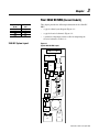
1
Non-Regenerative
DC Bus Supply Unit
(NRU)
Bulletin 2364E
User Manual
Important User Information
Solid state equipment has operational characteristics differing from those of
electromechanical equipment. “Safety Guidelines for the Application,
Installation and Maintenance of Solid State Controls” (Publication SGI-1.1
available from your local Allen-Bradley Sales Office or online at http://
www.ab.com/manuals/gi) describes some important differences between
solid state equipment and hard-wired electromechanical devices. Because of
this difference, and also because of the wide variety of uses for solid state
equipment, all persons responsible for applying this equipment must satisfy
themselves that each intended application of this equipment is acceptable.
In no event will the Allen-Bradley Company be responsible or liable for
indirect or consequential damages resulting from the use or application of
this equipment.
The examples and diagrams in this manual are included solely for
illustrative purposes. Because of the many variables and requirements
associated with any particular installation, the Allen-Bradley Company
cannot assume responsibility or liability for actual use based on the
examples and diagrams.
No patent liability is assumed by Allen-Bradley Company with respect to
use of information, circuits, equipment, or software described in this
manual.
Reproduction of the contents of this manual, in whole or in part, without
written permission of the Allen-Bradley Company is prohibited.
Throughout this manual we use notes to make you aware of safety
considerations.
!
ATTENTION: Identifies information about practices or
circumstances that can lead to personal injury or death, property
damage, or economic loss.
Attentions help you:
• identify a hazard
• avoid the hazard
• recognize the consequences
Important: Identifies information that is especially important for successful
application and understanding of the product.
Shock Hazard labels may be located on or inside the drive to
alert people that dangerous voltage may be present.
Summary of Changes
Updated Information
This manual incorporates the information found in the previous two
manuals:
• Non-Regenerative DC Bus Supply, Publication 2364E-5.01
August 1997
•
Non-Regenerative DC Bus Supply, Publication 2364E-5.01
March 1998
It also contains new information.
Updates and Additions
The information below summarizes the changes to this manual since
its last release:
Page
C-7
C-8
Description
Replaced two figures for one graphic. Figure 10: Phase-Loss Relay Wiring
Diagram
Section: Setting Jumpuers for The Phase-Loss Relay removed
Publication 2364E-5.01 April 2002
2-soc
Summary of Changes
End of Summary of Changes
Publication 2364E-5.01 April 2002
Table of Contents
Preface
Who Should Use This Manual . . . . . . . . . . . . . . . . . . . . . . .
Purpose of This Manual . . . . . . . . . . . . . . . . . . . . . . . . . . . .
Safety Precautions . . . . . . . . . . . . . . . . . . . . . . . . . . . . . . . .
Contents of this Manual . . . . . . . . . . . . . . . . . . . . . . . . . . . .
Related Documentation . . . . . . . . . . . . . . . . . . . . . . . . . . . .
Common Techniques Used in this Manual . . . . . . . . . . . . .
Drive System Receiving . . . . . . . . . . . . . . . . . . . . . . . . . . .
Rockwell Automation Support . . . . . . . . . . . . . . . . . . . . . .
P-1
P-1
P-1
P-3
P-4
P-5
P-5
P-5
Local Product Support . . . . . . . . . . . . . . . . . . . . . . . . . . . . . . . . P-5
Technical Product Assistance . . . . . . . . . . . . . . . . . . . . . . . . . . . P-5
Chapter 1
Overview
What is the 2364E? . . . . . . . . . . . . . . . . . . . . . . . . . . . . . . . 1-1
What does the NRU do? . . . . . . . . . . . . . . . . . . . . . . . . . . . . . . . 1-1
How will the NRU fit into a 2362 drive system? . . . . . . . . . . . . 1-2
How will the NRU fit into a drive system packaged in
FD86N enclosures? . . . . . . . . . . . . . . . . . . . . . . . . . . . . . . . . 1-2
How Does An NRU Work? . . . . . . . . . . . . . . . . . . . . . . . . . 1-3
Primary Electrical Components of the NRU . . . . . . . . . . . . . . . 1-3
NRU Conceptual Schematic . . . . . . . . . . . . . . . . . . . . . . . . . . . . 1-5
Power Conversion Operation . . . . . . . . . . . . . . . . . . . . . . . . . . . 1-6
Bulletin 2364E NRU – Standard Features . . . . . . . . . . . . . . 1-7
Electrical System Features . . . . . . . . . . . . . . . . . . . . . . . . . . . . . 1-7
Packaging Features . . . . . . . . . . . . . . . . . . . . . . . . . . . . . . . . . . . 1-7
Bulletin 2364E NRU – Standard Options . . . . . . . . . . . . . . 1-9
Electrical System Options . . . . . . . . . . . . . . . . . . . . . . . . . . . . . 1-9
Packaging Options . . . . . . . . . . . . . . . . . . . . . . . . . . . . . . . . . . 1-10
Chapter 2
Your 180A DC NRU (Current Code A)
180A DC System Layout . . . . . . . . . . . . . . . . . . . . . . . . . . . 2-1
180A DC NRU Electrical Schematic . . . . . . . . . . . . . . . . . . 2-2
Chapter 3
Your 350A DC NRU (Current Code B)
350A DC System Layout . . . . . . . . . . . . . . . . . . . . . . . . . . . 3-1
350A DC NRU Electrical Schematic . . . . . . . . . . . . . . . . . . 3-2
Chapter 4
Your 900A DC NRU (Current Code C)
900A DC System Layout . . . . . . . . . . . . . . . . . . . . . . . . . . . 4-1
900A DC NRU Electrical Schematic . . . . . . . . . . . . . . . . . . 4-2
Chapter 5
Your 1500A DC NRU (Current Code D)
1500A DC System Layout . . . . . . . . . . . . . . . . . . . . . . . . . . 5-1
1500A DC NRU Electrical Schematic . . . . . . . . . . . . . . . . . 5-2
Publication 2364E-5.01 April 2002
toc–ii
Table of Contents
Chapter 6
Your 2000A DC NRU (Current Code E)
2000A DC System Layout . . . . . . . . . . . . . . . . . . . . . . . . . . 6-1
2000A DC NRU Electrical Schematic . . . . . . . . . . . . . . . . . 6-2
Chapter 7
Your 2500A DC NRU (Current Code F)
2500A DC System Layout . . . . . . . . . . . . . . . . . . . . . . . . . . 7-1
2500A DC NRU Electrical Schematic . . . . . . . . . . . . . . . . . 7-2
Chapter 8
Your 3000A DC NRU (Current Code G)
3000A DC System Layout . . . . . . . . . . . . . . . . . . . . . . . . . . 8-1
3000A DC NRU Electrical Schematic . . . . . . . . . . . . . . . . . 8-2
Chapter 9
Installing Your NRU
Before You Begin . . . . . . . . . . . . . . . . . . . . . . . . . . . . . . . . 9-1
Documentation . . . . . . . . . . . . . . . . . . . . . . . . . . . . . . . . . . . . . . 9-1
Equipment . . . . . . . . . . . . . . . . . . . . . . . . . . . . . . . . . . . . . . . . . 9-1
Tools . . . . . . . . . . . . . . . . . . . . . . . . . . . . . . . . . . . . . . . . . . . . . . 9-1
Installation Procedure . . . . . . . . . . . . . . . . . . . . . . . . . . . . . 9-2
Ground-Fault Detection Option . . . . . . . . . . . . . . . . . . . . . . . . . 9-4
NRU Checks Before Power Up . . . . . . . . . . . . . . . . . . . . . . 9-5
NRU Checks After Power Up . . . . . . . . . . . . . . . . . . . . . . . 9-6
Chapter 10
Troubleshooting
Before You Begin . . . . . . . . . . . . . . . . . . . . . . . . . . . . . . . 10-1
Documentation . . . . . . . . . . . . . . . . . . . . . . . . . . . . . . . . . . . . . 10-1
Tools . . . . . . . . . . . . . . . . . . . . . . . . . . . . . . . . . . . . . . . . . . . . . 10-1
Safety Precautions . . . . . . . . . . . . . . . . . . . . . . . . . . . . . . . 10-1
Checklist for Troubleshooting
Your NRU . . . . . . . . . . . . . . . . . . . . . . . . . . . . . . . . . . . . . 10-2
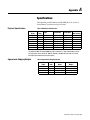
Appendix A
Specifications
Physical Specifications . . . . . . . . . . . . . . . . . . . . . . . . . . . . A-1
Approximate Shipping Weights . . . . . . . . . . . . . . . . . . . . . . A-1
Electrical Specifications . . . . . . . . . . . . . . . . . . . . . . . . . . . A-2
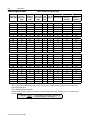
Functional Specifications . . . . . . . . . . . . . . . . . . . . . . . . . . . . . A-3
Input Currents of NRU with Control Source Upgrade Options A-4
Thru Bus Ratings per Unit . . . . . . . . . . . . . . . . . . . . . . . . . . . . A-5
Environmental Specifications . . . . . . . . . . . . . . . . . . . . . . . A-5
Operating Conditions . . . . . . . . . . . . . . . . . . . . . . . . . . . . . . . . A-5
Storage Conditions . . . . . . . . . . . . . . . . . . . . . . . . . . . . . . . . . . A-8
Publication 2364E-5.01 April 2002
Table of Contents
Appendix B
toc–iii
NRU Catalog Numbers and Spare Parts Kits
Understanding Catalog Numbers . . . . . . . . . . . . . . . . . . . . . B-1
Determining Catalog Numbers . . . . . . . . . . . . . . . . . . . . . . . . .B-1
NRU Catalog Numbers . . . . . . . . . . . . . . . . . . . . . . . . . . . . B-2
Bulletin 2364E NRU
Spare Parts Kits . . . . . . . . . . . . . . . . . . . . . . . . . . . . . . . . . . B-4
What Does a Spare Parts Kit Include? . . . . . . . . . . . . . . . . . . . .B-4
Which Table Do I Use? . . . . . . . . . . . . . . . . . . . . . . . . . . . . . . .B-4
Significance of Level Numbers . . . . . . . . . . . . . . . . . . . . . . . . .B-4
Definition of Terms Used to Describe "Qty in Kit" . . . . . . . . . .B-5
Catalog Number Description . . . . . . . . . . . . . . . . . . . . . . . . . . .B-5
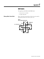
Appendix C
NRU Details
Wireway Meter Cover Details . . . . . . . . . . . . . . . . . . . . . . . C-1
MCC AC Input Entry Area . . . . . . . . . . . . . . . . . . . . . . . . . C-3
AC Input Customer Connection Details . . . . . . . . . . . . . . . C-4
Recommended Disconnect Trip Settings . . . . . . . . . . . . . . . C-5
Phase-Loss Relay . . . . . . . . . . . . . . . . . . . . . . . . . . . . . . . . . C-7
Installation and Setup . . . . . . . . . . . . . . . . . . . . . . . . . . . . . . . . .C-7
Monitor Operation. . . . . . . . . . . . . . . . . . . . . . . . . . . . . . . . . . . .C-8
Reset . . . . . . . . . . . . . . . . . . . . . . . . . . . . . . . . . . . . . . . . . . . . . .C-8
MCC Bus Location Details . . . . . . . . . . . . . . . . . . . . . . . . . C-9
Publication 2364E-5.01 April 2002
toc–iv
Table of Contents
This page intentionally left blank.
Publication 2364E-5.01 April 2002
Preface
Read this preface to familiarize yourself with the rest of this manual.
This preface covers the following topics:
Who Should Use This Manual
•
who should use this manual
•
the purpose of this manual
•
safety precautions
•
contents of this manual
•
related documentation
•
conventions used in this manual
•
drive system receiving
•
Rockwell Automation support
Use this manual if you are responsible for installing or operating a
Rockwell Automation non-regenerative, common DC bus supply unit
(NRU™).
If you do not have a basic understanding of the NRU, contact your
local Rockwell Automation Drive Systems representative for
information before using this product.
Purpose of This Manual
This manual provides installation and software configuration
instructions for Rockwell Automation’s NRUs.
Safety Precautions
The following general precautions apply to Bulletin 2364E NRUs and
to drive system lineups:
!
ATTENTION: Only those familiar with the drive
system, the products used in the system, and the
associated machinery should plan or implement the
installation, startup, and future maintenance of the
system. Failure to comply can result in personal injury
and/or equipment damage.
ATTENTION: Only connect Rockwell Automation
common DC bus AC drives to the NRU’s common DC
bus output.
Publication 2364E-5.01 April 2002
P-ii
Preface
!
ATTENTION: Verify that all sources of AC and DC
power are deenergized and locked out or tagged out in
accordance with the requirements of ANSI/NFPA 70E,
Part II.
ATTENTION: The system may contain stored energy
devices. To avoid the hazard of electrical shock, verify
that all voltage on capacitors has been discharged before
attempting to service, repair, or remove a drive system
or its components. You should only attempt the
procedures in this manual if you are qualified to do so
and are familiar with solid-state control equipment and
the safety procedures in publication NFPA 70E.
ATTENTION: An incorrectly applied or installed
drive system can result in component damage and/or a
reduction in product life. Wiring or application errors
— such as undersizing the motor, incorrect or
inadequate AC supply, and excessive ambient
temperatures — can result in the malfunction of the
drive equipment.
ATTENTION: This drive system contains ESD
(electrostatic discharge) sensitive parts and assemblies.
Static control precautions are required when installing,
testing, or repairing this assembly. Component damage
can result if ESD control procedures are not followed.
If you are not familiar with static control procedures,
refer to Rockwell Automation publication 8000-4.5.2,
Guarding Against Electrostatic Damage, or any other
applicable ESD protection handbook.
Publication 2364E-5.01 April 2002
Preface
P-iii
Contents of this Manual
Chapter
1
2
3
4
5
6
7
8
9
10
Title
Preface
Overview
Your 180A DC NRU (Current Code A)
Your 350A DC NRU (Current Code B)
Your 900A DC NRU (Current Code C)
Your 1500A DC NRU (Current Code D)
Your 2000A DC NRU (Current Code E)
Your 2500A DC NRU (Current Code F)
Your 3000A DC NRU (Current Code G)
Installing Your NRU
Troubleshooting
Appendix A Specifications
Appendix B NRU Catalog Numbers and Spare Parts Kits
Appendix C NRU Details
Contents
Purpose, background, and scope of this manual
Theory of operation, features, and standard options
Schematics and connection diagrams for the 180A DC NRU
Schematics and connection diagrams for the 350A DC NRU
Schematics and connection diagrams for the 900A DC NRU
Schematics and connection diagrams for the 1500A DC NRU
Schematics and connection diagrams for the 2000A DC NRU
Schematics and connection diagrams for the 2500A DC NRU
Schematics and connection diagrams for the 3000A DC NRU
NRU wiring information and installation procedures
Checklist for identifying problems with your 2364E system
Physical, electrical, environmental, and functional specifications
for the 2364E
Catalog number descriptions of available NRUs
NRU details including AC input connections and wireway meter
covers
Publication 2364E-5.01 April 2002
P-iv
Preface
Related Documentation
The following documents contain additional information concerning
related Rockwell Automation products and related standards. To
obtain a copy of Rockwell Automation publications, contact your
local Rockwell Automation office or distributor.
For
Information on the 1336 Force™ drives
Information on the 1336 Plus drives
Information on 1336 dynamic braking modules
consisting of both chopper and resistors
Information on 1336 braking chopper modules
PLC-5™ information
Bulletin 1403 Powermonitor II information
Information on the Bulletin 1403 communication
module
Additional Information on joining and splicing
together MCCs
Details on receiving, handling, and storing MCCs
Provides procedures for those tasks that need to
be done at the customer’s site before system start
up
A description of Drive Tools™ software
Information on SA3000 drives
Information on SA3100 drives
Information on FD86N enclosures
An article on wire sizes and types for grounding
electrical equipment
An article on safety procedures
Read This Document
1336T User Manual — AC Drive
1336S User Manual — .05-600HP
Installation Data — HD Dynamic Braking
Chopper Brake Module Installation Instructions 1336-5.65
PLC-5 Controllers Brochure
Bulletin 1403 Powermonitor II
Smart Communications Card
1785-1.2
1403-5.0
1403-5.1
Instructions — Joining and Splicing Vertical
2100-5.1
Instructions — Receiving, Handling, and
Storing Motor Control Centers
Bulletin 2300 Installation Manual
2100-5.5
Drive Tools Software Brochure
SA3000 Binder
SA3100 Binder
FD86N Drive Systems Enclosure Hardware
Installation Manual
National Electrical Code
9303-1.0
S-3001
S-3053
S-3062
2300-5.1
ANSI / NFPA 70 Published
by the National Fire
Protection Association of
Boston, MA
Standard for Electrical Safety Requirements for ANSI / NFPA 70E
Employee Workplaces
Allen-Bradley Publication Index
SD499
A complete listing of current documentation,
including ordering instructions. Also indicates
whether the documents are available on CD-ROM
or in multi-languages
A glossary of industrial automation terms and
Industrial Automation Glossary
abbreviations
Publication 2364E-5.01 April 2002
Document Number
1336 FORCE-5.12
1336 PLUS-5.0
1336-5.64
AG-7.1
Preface
Common Techniques Used in this
Manual
P-v
The following conventions are used throughout this manual:
•
NRU unit configurations are referred to by their catalog string
current code (Refer to Appendix B for code definition.).
•
Bulleted lists such as this one provide information, rather than
procedural steps.
•
Numbered lists provide sequential steps or hierarchical
information.
•
When you are referred to another location, the section name
appears in italics.
•
The exclamation point inside of a triangle followed by the word
"ATTENTION" indicate circumstances that can lead to personal
injury, death, property damage, or economic loss.
Drive System Receiving
You, the customer, are responsible for thoroughly inspecting the
equipment before accepting the shipment from the freight company.
Check the item(s) that you receive against your purchase order. If any
items are obviously damaged, it is your responsibility to refuse
delivery until the freight agent has noted the damage on the freight
bill. Should you discover any concealed damage during unpacking,
you are responsible for notifying the freight agent. Leave the shipping
container intact and request that the freight agent make a visual
inspection of the equipment.
Rockwell Automation Support
Rockwell Automation offers support services worldwide, with Sales/
Support Offices, authorized distributors, and authorized Systems
Integrators located throughout the United States, plus Rockwell
Automation representatives in every major country in the world.
Local Product Support
Contact your local Rockwell Automation representative for:
•
sales and order support
•
product technical training
•
warranty support
•
support service agreements
Technical Product Assistance
If you need to contact Rockwell Automation for technical assistance,
please review the product and troubleshooting information in this
manual first. Then, call your local Rockwell Automation
representative. For the quickest possible response, we recommend
that you have the catalog numbers of your products available when
you call.
Publication 2364E-5.01 April 2002
P-vi
Preface
This page intentionally left blank.
Publication 2364E-5.01 April 2002
Chapter
1
Overview
This chapter introduces Rockwell Automation’s Bulletin 2364E
common DC bus, non-regenerative unit (NRU), describes the theory
of NRU operation, and provides comprehensive lists of NRU features
and standard options. Appendix A contains specifications on
available NRUs. Appendix B contains NRU catalog numbers with
descriptions. Appendix C provides some other details concerning AC
input connections, bus locations, and wireway meter covers.
What is the 2364E?
We designed the NRU to be our single-direction power converter for
the front-end of a common DC bus drive system. Read this section
for a general description of NRU functionality and packaging.
What does the NRU do?
The NRU converts an incoming 3-phase, AC line voltage into:
•
a common DC bus voltage and current
•
a 115V AC NRU control voltage via a basic capacity control
transformer (Control power source upgrade options allow you to
select an increased transformer capacity to supply control power
to a 115V AC control bus)
The NRU applies the common bus DC voltage to the system power
bus and the 115V AC control voltage to a system control bus, if
desired. The system power bus and the control bus, if present, then
supply the voltage(s) to the remainder of the system.
Publication 2364E-5.01 April 2002
1-2
Overview
How will the NRU fit into a 2362 drive system?
We packaged the NRU in CENTERLINE ™ Bulletin 2100 motor
control centers (MCC) to be compatible with our existing 2362 AC
drive system lineups. As an added convenience, you can connect
other MCCs to both the right and left sides of an NRU.
How will the NRU fit into a drive system packaged in FD86N
enclosures?
FD86N enclosure options permit direct connection to Bulletin 2100
CENTERLINE MCCs that:
Publication 2364E-5.01 April 2002
•
are 20" deep
•
have 1.5"-high base channels
•
have the DC power bus and control bus (if selected) mounted at a
depth of 16.94" from the front of the MCC
Overview
How Does An NRU Work?
1-3
To help you to understand the theory behind how an NRU works, read
this section for descriptions of the primary electrical components, a
conceptual schematic, and a discussion of rectifier bridge operation.
Primary Electrical Components of the NRU
The primary electrical components of the NRU are:
•
a 3-phase circuit breaker or motor circuit protector, depending
upon NRU rating
•
AC line, current-limiting fuses
•
a six-pulse, full-wave, 3-phase-diode-bridge rectifier unit
•
a DC bus choke
•
a control power transformer
•
primary and secondary control transformer fusing
Motor Circuit Protector
The motor circuit protector is the switching device between the NRU
and the 3-phase AC source used to turn power to the system on and
off; it also provides magnetic overload protection. Motor circuit
protectors are standard features in 180A DC and 350A DC NRUs.
3-Phase Circuit Breaker
The 3-phase circuit breaker is the switching device between the NRU
and the 3-phase AC source used to turn power to the system on and
off; it also provides overcurrent trip and magnetic overload
protection. 3-phase circuit breakers are standard features in 900A
DC, 1500A DC, 2000A DC, 2500A DC, and 3000A DC NRUs.
AC Line, Current-Limiting Fuses
These fuses are located between the circuit breaker (or motor circuit
protector) and the diode-bridge rectifier unit. This fusing protects the
diodes from excessive currents and provides a current-limiting action
that permits a circuit breaker or motor circuit protector (with a
withstand rating less than 65,000A AC fault current available) to
effectively provide an AIC rating of 65,000A AC.
Publication 2364E-5.01 April 2002
1-4
Overview
Six-Pulse, Full-Wave, 3-Phase-Diode-Bridge Rectifier Unit
The bridge rectifier converts the 3-phase AC power to DC.
DC Bus Choke
The DC bus choke reduces peak currents in the AC line and the
bridge circuit. The DC bus choke also reduces line harmonics.
Control Power Transformer
This transformer steps down 2 phases of the 3-phase AC line voltage
to a single-phase, 115V AC control signal.
Primary and Secondary Control Transformer Fusing
Control transformer fusing protects the transformer and control
circuitry from excessive currents.
Publication 2364E-5.01 April 2002
Overview
1-5
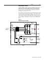
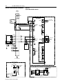
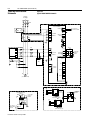
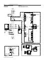
NRU Conceptual Schematic
Customer-supplied, 3-phase AC power is supplied to the system as
shown on the left side of the NRU schematic shown in Figure 1.1.
All three phases are fused and then connected to the diode-bridge
rectifier, as shown. The diode-bridge rectifier is also connected
through DC bus chokes to the DC bus.
Two of the three AC input phases are routed through primary control
transformer fusing to the control transformer. The secondary of the
control transformer, which supplies the NRU control power, can be
connected to the control bus after fusing if the control transformer is
sized accordingly. The bridge fan is connected to the NRU control
power.
Figure 1.1
Conceptual Schematic of the NRU
Diode Bridge
Circuit
Breaker
or MCP
DC +
Choke
+
Fuses
Bus
Voltage
Light
3-Phase AC
Incoming
Power
DC Choke
(This fuse included in control
power source upgrade options)
DC
Bus
L
L
M
Bridge
Fan
Motor
(Optional Air-Flow
Sensor)
115V AC
NRU Control
Power
N
Control
Transformer
To Optional
115V AC
Control Bus
N
NRU
Publication 2364E-5.01 April 2002
1-6
Overview
Power Conversion Operation
The diodes in the rectifier bridge will only permit current flow in one
direction, from anode to cathode. When an AC voltage is applied to a
diode, the output of that diode is a pulsating DC signal (positive halfcycles only).
For any particular phase, the anode of the upper diode is positive
relative to its cathode during the positive half-cycle of the AC input.
This forward (voltage) biases the upper diode and it conducts.
Meanwhile, the anode of the lower diode is negative relative to its
cathode. This reverse biases the lower diode and it does not conduct.
Similarly, during the negative half-cycle of the AC input, the lower
diode conducts and the upper diode does not conduct.
During the operation of a 3-phase bridge rectifier, multiple upper and/
or lower diodes may simultaneously be biased correctly for
conduction.
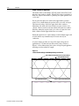
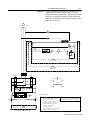
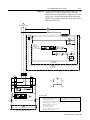
A 3-phase bridge provides an average DC output voltage that is
approximately 1.35 times the rms line-to-line voltage. Refer to
Figure 1.2 for an illustration of the 3-phase AC input signal applied to
the bridge rectifier and the DC output.
Figure 1.2
3-Phase AC Line Voltage and DC Output Voltage and Current
Typical Output Voltage Waveform From Diode Bridge
Average DC Bus Voltage
0
Typical DC Choke Current
0
Publication 2364E-5.01 April 2002
Typical 3-Phase AC Input Waveform
Overview
Bulletin 2364E NRU –
Standard Features
1-7
Electrical System Features
•
A 3-phase circuit breaker / motor circuit protector rated for
65kAIC:
• 180 and 350A DC units have motor circuit protectors
• 900, 1500, 2000, 2500, and 3000A DC units have circuit
breakers
•
AC line, current-limiting fuses rated at 600V AC with short
circuit protection rated at 65kAIC
•
A six-pulse, full-wave, 3-phase-diode-bridge rectifier unit
•
A DC bus choke with inductance in both +/- legs
•
A "basic capacity" control power transformer that supplies ONLY
the NRU with single-phase, 115V AC control power
•
Primary and secondary control transformer fusing (excluding the
control bus fuse that is supplied with the "6P" and "6PX" control
power source upgrade options)
•
A "DC-Bus-Energized" pilot light that turns on when the bus
voltage is above 50V DC
•
Compatible with Bulletin 1336 dynamic braking (DB) chopper
units
Note: A dynamic braking chopper unit requires an additional
cabinet section.
•
A bridge suppressor module
•
Configurations available for 230, 380, 460, and 575V AC inputs
with 180, 350, 900, 1500, 2000, 2500, and 3000A DC outputs
•
Utilization of #16 AWG MTW (PVC insulated) rated, stranded
copper control wiring
Packaging Features
•
Utilization of Bulletin 2100 CENTERLINE motor control center
(MCC) packaging makes the NRU compatibility with other
Bulletin 2100 and 2300 products
•
Unit depth of 20"
•
DC bus and control bus (if selected) depth at
•11.9 inches in 180 and 350A DC (current codes A and B)
units
•16.9 inches in 900, 1500, 2000, 2500, and 3000A DC (current codes C, D, E, F, and G) units
Publication 2364E-5.01 April 2002
1-8
Overview
•
Ability to connect to other MCC sections on both the right and
left sides
•
Top-entry AC line input
•
Removable top-plate for cutting conduit holes
•
6"-high, full-section-depth, horizontal wireway at top of MCC
enclosure
Note: The front-half of the top horizontal wireway is typically
reserved for the routing of control/communication wires.
•
Easy accessibility for routine maintenance
•
Motor circuit protector in 180 and 350A DC (current codes A and
B) units and circuit breakers in 900, 1500, 2000, 2500, and
3000A DC (current codes C, D, E, F, and G) units are
padlockable
•
180 and 350A DC (current codes A and B) units have removable
diode power bridge assembly
•
Tin-plated copper horizontal power busbars and PE/TE busbars
•
Standard power bus bracing rated at 65kAIC
•
Horizontal PE and TE copper bus that is bottom-front mounted
•
ASA49 gray, baked-enamel finish
•
Vented unit door(s) with door fan(s) where appropriate
•
Units come standard with cloth wire labels
•
NRUs can connect to FD86N enclosures on either or both sides,
provided that the NRU:
• is 20 inches deep
• has 1.5" high base channels
• has its DC bus and control bus (if supplied) mounted at a
depth of 16.94 inches
Publication 2364E-5.01 April 2002
Overview
Bulletin 2364E NRU –
Standard Options
1-9
Electrical System Options
•
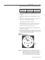
Analog DC bus voltage metering
•
Analog AC input current metering (Phase A only)
Note: The bus voltmeter and/or AC input ammeter are mounted
in a special wireway meter cover that is angled for easy viewing.
•
AC input and output power metering (kW) using Powermonitor II
(Bulletin 1403) for NRUs powered by 3-phase, grounded-wye
secondary supplies
•
Powermonitor II communication module for connecting the
Powermonitor II to Remote I/O, RS-232, or RS-485 devices
•
A door-mounted "Unit-Not-Faulted" pilot light that monitors air
flow sensor(s), heatsink temperature sensors, phase loss relay,
and an optional remote interlock (if supplied by customer)
•
A door-mounted, ground-fault detection meter for NRUs
powered by 3-phase, grounded-wye secondary supplies
•
Standard capacity ("6P") and extra capacity ("6PX") control
power source upgrade options are available to provide 115V AC
control bus power
Note: "6P" and "6PX" options include control bus fuse and
control busbar mounted in cabinet above power bus.
•
An air-flow-loss switch in all Diode Power MCC sections and in
2500/3000A DC Input Power MCC sections. This option
monitors critical NRU air flows for proper CFM
•
A line RC suppressor module to reduce AC line transients
Note: The line RC suppressor module is recommended when the
primary voltage of the supply transformer is 2300V AC or
greater.
Publication 2364E-5.01 April 2002
1-10
Overview
Packaging Options
•
Tin-plated control bus mounted in rear of cabinet above the
power bus
Note: Control bus is included as part of the control power source
upgrade options.
•
Depth of DC bus and control bus (if supplied) at 16.9 inches in
180 and 350A DC (current codes A and B) units
•
115V AC, 15A duplex receptacle
Note: Customer supplies single-phase, 115V AC power and
wiring to the duplex receptacle.
•
A phone jack
•
Gasketed unit door areas and door-fan filters
•
Brady Datab™ wire labels offering the added protection of a
clear plastic cover on top of the labels
Note: Units come standard with cloth wire labels.
Publication 2364E-5.01 April 2002
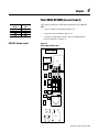
Chapter
2
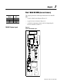
Your 180A DC NRU (Current Code A)
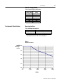
Input Voltage
(V AC)
230
380
460
575
Rated DC Bus
kW
56
92
112
140
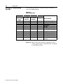
180A DC System Layout
This chapter provides the following information for the 180A DC
NRU:
• a typical cabinet layout diagram (Figure 2.1)
•
a typical electrical schematic (Figure 2.2)
•
a symbol-to-component reference table for interpreting the
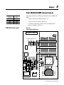
electrical schematic (Table 2.A)
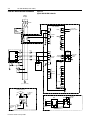
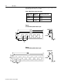
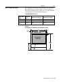
Figure 2.1
Typical 180A DC NRU Layout
VM1
AM1
EA1
TB2
MCP1
TB1
EA3
F8
CT1
F14,
F15,
F16
F11,
F12,
F13
CT3
R11, R12
D11
SP1
SP2
C11
F1
S1
S2
SP3
SP4
F2
CR1
F3
CR2
PS1
F7
HS1
(-)
HS2
(+)
MTR1-C
EA5
F4,
F6
MTR1
EA2
CH11
PT1
Publication 2364E-5.01 April 2002
2-2
Your 180A DC NRU (Current Code A)
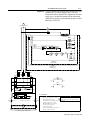
180A DC NRU Electrical Schematic
Figure 2.2
Typical 180A DC NRU Schematic
3-Phase
AC Input
MCP1
EA1
Powermonitor II
MASTER MODULE
BULL 1403-MM05A
I1+
CT1
AM1
L1 (+)
POWER
GRD
I2+
X1
H1
H1
CT1
X1
I2-
CURRENT
I3+
INPUTS
AIN
ANALOG
INPUT
ACOM
I3-
CT3
X2
X2
115 VAC NRU
CONTROL POWER
L2 (-)
I1-
I4+
R14
I4-
R11
R12
PE
R24
R21
R22
EA3
F14
EA1-A
F11
L1
BULL
V1
1403-DMA
F15
F12
L2
COMMON
V2
F13
F16
L3
TX
TX
L1(+)
RX
RX
L2 (-)
115 VAC NRU
CONTROL
POWER
INPUTS
V3
A
SP4
DISPLAY
MODULE
VOLTAGE
B
1403-NSC
BULL
C
N
SP1
CR1
PE
1
SP2
RIO
PE
2
S1
SHLD
SP3
S2
STATUS
S3
+
INPUTS
RS-485
S4
SHLD
SCOM
TXD
A
RS-232
RXD
SG
(GO TO NEXT PAGE)
SHLD
TO POWER TRANSFORMER
GROUNDING RESISTOR
PE
TB2-1
VM
2
TB2-2
10
12
(INPUT)
115 VAC NRU
CONTROL
POWER
9
7
(115VAC)
EA5
S5
METER RELAY
2
4
6
TB1-7
TO CONTACTOR
MONITORING
CIRCUIT
TB1-8
Publication 2364E-5.01 April 2002
PE
Y
J2
1
R
2
B
FLOW
SENSOR
ACL
J2
5
+
6
-
ACN
ACG
24 VDC
3
J1 1
115VAC NRU
CONTROL
POWER
PS1
3
TO CONTACTOR
MONITORING
CIRCUIT
Your 180A DC NRU (Current Code A)
2-3
Important: The Powermonitor II standard configuation works with
grounded-wye secondary supplies only. For more
information on Powermonitor II configurations for other
supply types, consult Powermonitor II documentation
and the Power Quality and Automation group located in
Milwaukee, WI, USA.
A
(FROM PREVIOUS PAGE)
F6
F4
PT1
(X1)
F8
115 VAC
F7
(X2)
MTR1
PE
TB1-9
TB1-1
OPTIONAL
REMOTE
INTERLOCK TB1-2
(JMPR)
TB1-10
EA5-CR
1
S1
S2
CR1
CR2
3
L1
N
PL2
115 VAC NRU
CONTROL POWER
115 VAC
CONTROL BUS TO
INVERTER UNITS
F1 F2 F3
HEAT
SINK
HEAT
SINK
-BUS
CR1
+BUS
D1
D2
D3
D4
TB1-3
D5 HS1
D6
CR2
HS2
TB1-5
D11
TB1-4
TB1-6
C11
R11
R12
EA2
+BUS
-BUS
F1
R1
F2
R2
LED1
LED2
(X3)
FOOTNOTES:
PL1
(X1)
CH11
CH11
(X4)
(X2)
VM1
DC HORIZONTAL BUS TO INVERTER UNITS
Note: An NRU may have either a door-
Door-mounted ammeter option.
mounted ammeter or a Powermonitor II. This
drawing shows both options for information.
Powermonitor II option.
Powermonitor II communication module option.
Line RC suppressor option.
Ground-fault detection option.
Air-flow sensing option.
Control bus option.
Unit-not-faulted pilot light option.
DC bus voltmeter option.
Publication 2364E-5.01 April 2002
2-4
Your 180A DC NRU (Current Code A)
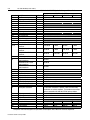
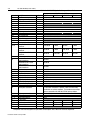
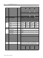
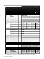
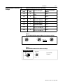
Table 2.A: 180A DC NRU Symbol-to-Component Cross Reference
Symbol
AM1
C11
CH11
CR1
CR2
CT1, CT3
D1 - 6
D11
EA1
EA2
EA2F1 - 2
EA3
EA5
F1 - 3
F11 - 13
F14 - 16
HS1 - 2
MCP1
MTR1
MTR1-C
PL1
PL2
PS1
PT1
Description
Ammeter monitoring L1
Bridge suppressor capacitor
DC choke
Phase-loss relay
Fault relay
Current transformer
Diodes
Bridge suppressor diode
Powermonitor II
Bus indicator PCB
Bus indicator PCB fuses
AC line RC suppressor PCB
Air flow sensor PCB
Incoming 3-phase, line fuses
Primary fuse for a 1 kVA control
transformer
Primary fuse for a 2 kVA control
transformer
Primary fuse for a 5 kVA control
transformer
NRU control power fuse
Control bus fuse for a 1 kVA
control transformer
Control bus fuse for a 2 kVA
control transformer
Control bus fuse for a 5 kVA
control transformer
Phase-loss fuses
RC suppressor fuses
Bridge heatsink
Motor circuit protector
Bridge fan
Bridge fan capacitor
DC-Bus-Energized pilot light
Unit-Not-Faulted pilot light
Air flow sensor power supply
Control power transformer
R11
R12
S1 - 2
S5
SP1 - 3
SP4
VM1
VM2
Bridge suppressor resistor
Bridge suppressor resistor
Heatsink thermoswitch
Air flow switch
Line-to-line MOVs
Neutral-to-ground MOV
DC bus voltmeter
Ground fault detector
F4, F6
F7
F8
Option
230V AC
200A
3 uF, 2000V
611 uH
AC 3-Phase Input Voltage
380V AC
460V AC
575V AC
200:5
450A,1800V AC
60A, 1700V
1A, 1000V, HVR, 1-3/32" diameter, 3" length, 500AIC
250A, 170M
6.25A, KLDR
4A, KLDR
3A, KLDR
3A, KLDR
12A, KLDR
8A, KLDR
6.25A, KLDR
5A, KLDR
30A, KLDR
17.5A, KLDR
15A, KLDR
12A, KLDR
2A, KLDR
6A, KLDR
15A, KLDR
35A, FRN
1A, KLDR
25A, KTKR
250A, J-frame
560 CFM
10 uF capacitor
24V AC/VDC, red, 800MR
120V AC, amber, 800MR
24V DC, 0.5A
A 1 kVA control transformer is standard, 2 kVA and 5 kVA control
transformers are available as options. This transformer has multiple
taps to accommodate 230, 380, 460, 575V AC primary voltages.
2.2 ohm, 100 W
100 ohm, 100 W
210 °F
360 J, 275V AC 460 J, 320V AC 460 J, 320V AC 550 J, 385V AC
600 J, 550V AC 760 J, 680V AC 760 J, 680V AC 760 J, 680V AC
750V DC
750V DC
1000V DC
1000V DC
Components marked as being options are part of NRU standard options. Not all NRUs will have these components.
Publication 2364E-5.01 April 2002
Chapter
3
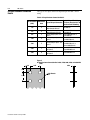
Your 350A DC NRU (Current Code B)
Input Voltage
(V AC)
230
380
460
575
Rated DC Bus
kW
109
179
217
271
350A DC System Layout
This chapter provides the following information for the 350A DC
NRU:
• a typical cabinet layout diagram (Figure 3.1)
•
a typical electrical schematic (Figure 3.2)
•
a symbol-to-component reference table for interpreting the
electrical schematic (Table 3.A)
Figure 3.1
Typical 350A DC NRU Layout
VM1
AM1
EA1
TB2
MCP1
TB1
EA3
F8
CT1
F14,
F15,
F16
F11,
F12,
F13
D11
SP1
SP2
CT3
R11, R12
C11
F1
S1
S2
SP3
SP4
F2
CR1
F3
CR2
PS1
F7
HS1
(-)
HS2
(+)
MTR1-C
EA5
F4,
F6
MTR1
EA2
CH11
PT1
Publication 2364E-5.01 April 2002
3-2
Your 350A DC NRU (Current Code B)
350A DC NRU Electrical Schematic
Figure 3.2
Typical 350A DC NRU Schematic
3-Phase
AC Input
MCP1
EA1
Powermonitor II
MASTER MODULE
BULL 1403-MM05A
I1+
CT1
AM1
L1 (+)
POWER
I1-
GRD
I2+
X1
H1
H1
CT1
X1
I2-
CURRENT
I3+
INPUTS
AIN
ANALOG
INPUT
ACOM
I3-
CT3
X2
X2
115 VAC NRU
CONTROL POWER
L2 (-)
I4+
R14
I4-
R11
R12
PE
R24
R21
R22
EA3
F14
EA1-A
F11
L1
F15
F12
L2
COMMON
V2
DISPLAY
MODULE
VOLTAGE
F13
F16
L3
TX
TX
L1(+)
RX
RX
L2 (-)
115 VAC NRU
CONTROL
POWER
INPUTS
V3
A
SP4
BULL
1403-DMA
V1
B
1403-NSC
BULL
C
N
SP1
CR1
PE
1
SP2
RIO
PE
2
S1
SHLD
SP3
S2
STATUS
S3
+
INPUTS
RS-485
S4
SHLD
SCOM
TXD
A
RS-232
RXD
SG
(GO TO NEXT PAGE)
SHLD
TO POWER TRANSFORMER
GROUNDING RESISTOR
PE
TB2-1
VM
2
TB2-2
10
12
(INPUT)
115 VAC NRU
CONTROL
POWER
9
7
(115VAC)
EA5
S5
METER RELAY
2
4
6
TB1-7
TO CONTACTOR
MONITORING
CIRCUIT
TB1-8
Publication 2364E-5.01 April 2002
PE
Y
J2
1
R
2
B
FLOW
SENSOR
PS1
ACL
J2
5
+
6
-
ACN
ACG
24 VDC
3
J1 1
115VAC NRU
CONTROL
POWER
3
TO CONTACTOR
MONITORING
CIRCUIT
Your 350A DC NRU (Current Code B)
3-3
Important: The Powermonitor II standard configuration works with
grounded-wye secondary supplies only. For more
information on Powermonitor II configurations for other
supply types, consult Powermonitor II documentation
and the Power Quality and Automation group located in
Milwaukee, WI, USA.
A
(FROM PREVIOUS PAGE)
F6
F4
PT1
(X1)
F8
115 VAC
F7
(X2)
MTR1
PE
TB1-9
TB1-1
OPTIONAL
REMOTE
INTERLOCK TB1-2
(JMPR)
TB1-10
EA5-CR
1
S1
S2
CR1
CR2
3
L1
N
PL2
115 VAC NRU
CONTROL POWER
115 VAC
CONTROL BUS TO
INVERTER UNITS
F1
HEAT
SINK
F2
F3
HEAT
SINK
-BUS
CR1
+BUS
D1
D2
D3
D4
TB1-3
HS1
D5
D6
CR2
HS2
TB1-5
D11
TB1-4
TB1-6
C11
R11
R12
EA2
+BUS
-BUS
F1
R1
F2
R2
LED1
LED2
(X3)
FOOTNOTES:
PL1
(X1)
CH11
CH11
(X4)
(X2)
VM1
DC HORIZONTAL BUS TO INVERTER UNITS
Note: An NRU may have either a door-
Door-mounted ammeter option.
mounted ammeter or a Powermonitor II. This
drawing shows both options for information.
Powermonitor II option.
Powermonitor II communication module option.
Line RC suppressor option.
Ground-fault detection option.
Air-flow sensing option.
Control bus option.
Unit-not-faulted pilot light option.
DC bus voltmeter option.
Publication 2364E-5.01 April 2002
3-4
Your 350A DC NRU (Current Code B)
Table 3.A: 350A DC NRU Symbol-to-Component Cross Reference
Symbol
AM1
C11
CH11
CR1
CR2
CT1, CT3
D1 - 6
D11
EA1
EA2
EA2F1 - 2
EA3
EA5
F1 - 3
F11 - 13
F14 - 16
HS1 - 2
MCP1
MTR1
MTR1-C
PL1
PL2
PS1
PT1
Description
Ammeter monitoring L1
Bridge suppressor capacitor
DC choke
Phase-loss relay
Fault relay
Current transformer
Diodes
Bridge suppressor diode
Powermonitor II
Bus indicator PCB
Bus indicator PCB fuses
AC line RC suppressor PCB
Air flow sensor PCB
Incoming 3-phase, line fuses
Primary fuse for a 1 kVA control
transformer
Primary fuse for a 2 kVA control
transformer
Primary fuse for a 5 kVA control
transformer
NRU control power fuse
Control bus fuse for a 1 kVA
control transformer
Control bus fuse for a 2 kVA
control transformer
Control bus fuse for a 5 kVA
control transformer
Phase-loss fuses
RC suppressor fuses
Bridge heatsink
Motor circuit protector
Bridge fan
Bridge fan capacitor
DC-Bus-Energized pilot light
Unit-Not-Faulted pilot light
Air flow sensor power supply
Control power transformer
R11
R12
S1 - 2
S5
SP1 - 3
SP4
VM1
VM2
Bridge suppressor resistor
Bridge suppressor resistor
Heatsink thermoswitch
Air flow switch
Line-to-line MOVs
Neutral-to-ground MOV
DC bus voltmeter
Ground fault detector
F4, F6
F7
F8
Option
230V AC
400A
32 uF, 2000V
319 uH
AC 3-Phase Input Voltage
380V AC
460V AC
575V AC
400:5
450A,1800V AC
60A, 1700V
1A, 1000V, HVR, 1-3/32" diameter, 3" length, 500AIC
450A, 170M fuse
6.25A, KLDR
4A, KLDR
3A, KLDR
3A, KLDR
12A, KLDR
8A, KLDR
6.25A, KLDR
5A, KLDR
30A, KLDR
17.5A, KLDR
15A, KLDR
12A, KLDR
2A, KLDR
6A, KLDR
15A, KLDR
35A, FRN
1A, KLDR
25A, KTKR
400A, K-frame
560 CFM
10 uF capacitor
24V AC/VDC, red, 800MR
120V AC, amber, 800MR
24V DC, 0.5A
A 1 kVA control transformer is standard, 2 kVA and 5 kVA control
transformers are available as options. This transformer has multiple
taps to accommodate 230, 380, 460, 575V AC primary voltages.
2.2 ohm, 100 W
100 ohm, 100 W
210 °F
360 J, 275V AC 460 J, 320V AC 460 J, 320V AC 550 J, 385V AC
600 J, 550V AC 760 J, 680V AC 760 J, 680V AC 760 J, 680V AC
750V DC
750V DC
1000V DC
1000V DC
Components marked as being options are part of NRU standard options. Not all NRUs will have these components.
Publication 2364E-5.01 April 2002
Chapter
4
Your 900A DC NRU (Current Code C)
Input Voltage
(V AC)
230
380
460
575
Rated DC Bus
kW
279
459
558
698
900A DC System Layout
This chapter provides the following information for the 900A DC
NRU:
• a typical cabinet layout diagram (Figure 4.1)
•
a typical electrical schematic (Figure 4.2)
•
a symbol-to-component reference table for interpreting the
electrical schematic (Table 4.A)
Figure 4.1
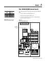
Typical 900A DC NRU Layout
AM1
VM1
EA1
CB1
EA3
SP1
SP2
SP3
SP4
CT1
CT3
F14
F15
F16
TB2
TB1
F1
F2
F3
F11
F12
F13
F8
CR1
F7
CR2
HS1
HS2
PS1
EA5
F4
F6
MTR1
EA2
CH11
PT1
Publication 2364E-5.01 April 2002
4-2
Your 900A DC NRU (Current Code C)
900A DC NRU Electrical Schematic
Figure 4.2
Typical 900A DC NRU Schematic
3-Phase
AC Input
CB1
EA1
Powermonitor II
MASTER MODULE
BULL 1403-MM05A
I1+
CT1
AM1
L1 (+)
POWER
I1-
GRD
I2+
X1
H1
H1
CT1
X1
I2-
CURRENT
I3+
INPUTS
AIN
ANALOG
INPUT
ACOM
I3-
CT3
X2
X2
115 VAC NRU
CONTROL POWER
L2 (-)
I4+
R14
I4-
R11
R12
PE
R24
R21
R22
EA3
F14
EA1-A
F11
L1
BULL
V1
1403-DMA
F15
F12
L2
COMMON
V2
F13
F16
L3
TX
TX
L1(+)
RX
RX
L2 (-)
115 VAC NRU
CONTROL
POWER
INPUTS
V3
A
SP4
DISPLAY
MODULE
VOLTAGE
B
1403-NSC
BULL
C
N
SP1
CR1
PE
1
SP2
RIO
PE
2
S1
SHLD
SP3
S2
STATUS
S3
+
INPUTS
RS-485
S4
SHLD
SCOM
TXD
A
RS-232
RXD
SG
(GO TO NEXT PAGE)
SHLD
TO POWER TRANSFORMER
GROUNDING RESISTOR
PE
TB2-1
VM
2
TB2-2
10
12
(INPUT)
115 VAC NRU
CONTROL
POWER
9
7
(115VAC)
EA5
S5
METER RELAY
2
4
6
TB1-7
TO CONTACTOR
MONITORING
CIRCUIT
TB1-8
Publication 2364E-5.01 April 2002
PE
Y
J2
1
R
2
B
3
FLOW
SENSOR
PS1
ACL
J2
5
+
6
-
ACN
ACG
24 VDC
J1 1
115VAC NRU
CONTROL
POWER
3
TO CONTACTOR
MONITORING
CIRCUIT
Your 900A DC NRU (Current Code C)
4-3
Important: The Powermonitor II standard configuration works with
grounded-wye secondary supplies only. For more
information on Powermonitor II configurations for other
supply types, consult Powermonitor II documentation
and the Power Quality and Automation group located in
Milwaukee, WI, USA.
A
(FROM PREVIOUS PAGE)
F6
F4
PT1
(X1)
F8
115 VAC
F7
(X2)
MTR1
PE
TB1-9
TB1-1
OPTIONAL
REMOTE
I N T E R L O C K TB1-2
(JMPR)
TB1-10
EA5-CR
1
S1
S2
CR1
CR2
3
L1
N
PL2
115 VAC NRU
CONTROL POWER
115 VAC
CONTROL BUS TO
INVERTER UNITS
F1
HEAT
SINK
F2
F3
HEAT
SINK
-BUS
CR1
+BUS
D1
D2
D3
D4
TB1-3
D5
HS1
D6
TB1-4
CR2
HS2
TB1-5
EA4
TB1-6
EA2
+BUS
-BUS
F1
R1
F2
R2
LED1
LED2
(X3)
FOOTNOTES:
PL1
(X1)
CH11
CH11
(X4)
(X2)
VM1
DC HORIZONTAL BUS TO INVERTER UNITS
Note: An NRU may have either a door-
Door-mounted ammeter option.
mounted ammeter or a Powermonitor II. This
drawing shows both options for information.
Powermonitor II option.
Powermonitor II communication module option.
Line RC suppressor option.
Ground-fault detection option.
Air-flow sensing option.
Control bus option.
Unit-not-faulted pilot light option.
DC bus voltmeter option.
Publication 2364E-5.01 April 2002
4-4
Your 900A DC NRU (Current Code C)
Table 4.A: 900A DC NRU Symbol-to-Component Cross Reference
Symbol
AM1
CB1
CH11
CR1
CR2
CT1, CT3
D1 - 6
EA1
EA2
EA2F1 - 2
EA3
EA4
EA5
F1 - 3
F11 - 13
F14 - 16
HS1 - 2
MTR1
MTR1-C
PL1
PL2
PS1
PT1
Description
Ammeter monitoring L1
Circuit Breaker
DC choke
Phase-loss relay
Fault relay
Current transformer
Diodes
Powermonitor II
Bus indicator PCB
Bus indicator PCB fuses
AC line RC suppressor PCB
Bridge suppressor PCB
Air flow sensor PCB
Incoming 3-phase, line fuses
Primary fuse for a 1 kVA control
transformer
Primary fuse for a 2 kVA control
transformer
Primary fuse for a 5 kVA control
transformer
NRU control power fuse
Control bus fuse for a 1 kVA
control transformer
Control bus fuse for a 2 kVA
control transformer
Control bus fuse for a 5 kVA
control transformer
Phase-loss fuses
RC suppressor fuses
Bridge heatsink
Bridge fan
Bridge fan capacitor
DC-Bus-Energized pilot light
Unit-Not-Faulted pilot light
Air flow sensor power supply
Control power transformer
S1 - 2
S5
SP1 - 3
SP4
VM1
VM2
Heatsink thermoswitch
Air flow switch
Line-to-line MOVs
Neutral-to-ground MOV
DC bus voltmeter
Ground fault detector
F4, F6
F7
F8
Option
AC 3-Phase Input Voltage
230V AC
380V AC
460V AC
1000A
1200A R-frame breaker with 1200A plug
124 uH
575V AC
1000:5
900A, 1800V AC
1A, 1000V, HVR, 1-3/32" diameter, 3" length, 500AIC
1000A, 170M
6.25A, KLDR
4A, KLDR
3A, KLDR
3A, KLDR
12A, KLDR
8A, KLDR
6.25A, KLDR
5A, KLDR
30A, KLDR
17.5A, KLDR
15A, KLDR
12A, KLDR
3A, KLDR
5A, KLDR
12A, KLDR
35A, FRN
1A, KLDR
25A, KTKR
710 CFM
16 uF capacitor
24V AC/VDC, red, 800MR
120V AC, amber, 800MR
24V DC, 0.5A
A 1 kVA control transformer is standard, 2 kVA and 5 kVA control
transformers are available as options. This transformer has multiple
taps to accommodate 230, 380, 460, 575V AC primary voltages.
210 °F
360 J, 275V AC 460 J, 320V AC 460 J, 320V AC 550 J, 385V AC
600 J, 550V AC 760 J, 680V AC 760 J, 680V AC 760 J, 680V AC
750V DC
750V DC
1000V DC
1000V DC
Components marked as being options are part of NRU standard options. Not all NRUs will have these components.
Publication 2364E-5.01 April 2002
Chapter
5
Your 1500A DC NRU (Current Code D)
Rated DC Bus
kW
465
765
930
1163
This chapter provides the following information for the 1500A DC
NRU:
• a typical cabinet layout diagram (Figure 5.1)
1500A DC System Layout
•
a typical electrical schematic (Figure 5.2)
•
a symbol-to-component reference table for interpreting the
electrical schematic (Table 5.A)
Figure 5.1
Typical 1500A DC NRU Layout
VM1
AM1
CUSTOMER
3-PHASE AC
INPUT
EA4
HS1
(-)
HS2
(+)
S1
S2
CB1
Phase
Phase
Phase
A
B
C
CT1
S3
CT3
Phase
A
Phase
B
Phase
C
F3
EA3
SP1
F2
SP4 F14,
F15,
F16
SP3
SP2
S5
F1
F4,
F6
F8
MTR3
TB2
TB1
F11,
F12,
F13
PS1
MTR1-C
Input Voltage
(V AC)
230
380
460
575
EA5
F7
MTR1
CR1 CR2
EA2
CH11
EA1
PT1
Publication 2364E-5.01 April 2002
5-2
Your 1500A DC NRU (Current Code D)
1500A DC NRU Electrical
Schematic
Figure 5.2
Typical 1500A DC NRU Schematic
3-Phase
AC Input
CB1
EA1
Powermonitor II
MASTER MODULE
BULL 1403-MM05A
I1+
CT1
AM1
POWER
X1
H1
CT1
X1
I2-
CURRENT
I3+
INPUTS
ANALOG
INPUT
AIN
ACOM
I3-
CT3
I4+
R14
I4-
R11
X2
X2
115 VAC NRU
CONTROL POWER
GRD
I2+
H1
L1 (+)
L2 (-)
I1-
R12
PE
R24
R21
R22
EA3
F14
L1
EA1-A
F11
BULL
V1
1403-DMA
F15
F12
L2
V2
DISPLAY
MODULE
VOLTAGE
COMMON
F13
F16
L3
TX
TX
L1(+)
RX
RX
L2 (-)
115 VAC NRU
CONTROL
POWER
INPUTS
V3
A
SP4
B
1403-NSC
BULL
C
N
SP1
CR1
PE
1
SP2
RIO
PE
2
S1
SHLD
SP3
S2
STATUS
S3
+
INPUTS
-
RS-485
S4
SHLD
SCOM
TXD
A
RS-232
RXD
SG
(GO TO NEXT PAGE)
SHLD
PE
EA5
S5
TO POWER TRANSFORMER
GROUNDING RESISTOR
TB2-1
VM
2
TB2-2
10
12
(INPUT)
115 VAC NRU
CONTROL
POWER
2
B
3
4
Publication 2364E-5.01 April 2002
115VAC NRU
CONTROL
POWER
6
PS1
J1 1
FLOW
SENSOR
3
ACL
ACN
+
TO CONTACTOR
MONITORING CIRCUIT
S6
6
TB1-8
J2
5
ACG
24 VDC
TB1-7
TO CONTACT
MONITORING
CIRCUIT
R
9
7
(115VAC)
METER RELAY
2
Y
J2
1
PE
EA6
Y
J2
1
R
2
B
3
FLOW
SENSOR
J2
5
6
J1 1
3
TO CONTACTOR
MONITORING CIRCUIT
Your 1500A DC NRU (Current Code D)
5-3
Important: The Powermonitor II standard configuration works with
grounded-wye secondary supplies only. For more
information on Powermonitor II configurations for other
supply types, consult Powermonitor II documentation
and the Power Quality and Automation group located in
Milwaukee, WI, USA.
A
(FROM PREVIOUS PAGE)
F6
F4
PT1
(X1)
F8
115 VAC
F7
(X2)
MTR1
PE
TB1-9
MTR2
TB1-1
OPTIONAL
REMOTE
I N T E R L O C K TB1-2
(JMPR)
EA6-CR
EA5-CR
1
3
1
CH11-TG
TB1-10
S3
3
S2
CR1
CR2
L1
N
S1
PL2
115 VAC NRU
CONTROL POWER
115 VAC
CONTROL BUS TO
INVERTER UNITS
F1
HEAT
SINK
F2
F3
HEAT
SINK
-BUS
CR1
+BUS
D1
D2
D3
D4
TB1-3
D5
HS1
D6
TB1-4
CR2
HS2
TB1-5
EA4
TB1-6
EA2
+BUS
-BUS
F1
R1
F2
R2
FOOTNOTES:
LED1
LED2
(X3)
PL1
Note: An NRU may have either a door(X1)
CH11
CH11
(X4)
(X2)
VM1
DC HORIZONTAL BUS TO INVERTER UNITS
Door-mounted ammeter option.
mounted ammeter or a Powermonitor II. This
drawing shows both options for information.
Powermonitor II option.
Powermonitor II communication module option.
Line RC suppressor option.
Ground-fault detection option.
Air-flow sensing option.
Control bus option.
Unit-not-faulted pilot light option.
DC bus voltmeter option.
Publication 2364E-5.01 April 2002
5-4
Your 1500A DC NRU (Current Code D)
Table 5.A: 1500A DC NRU Symbol-to-Component Cross Reference
Symbol
AM1
CB1
CH11
CH11-TG
CR1
CR2
CT1, CT3
D1 - 6
EA1
EA2
EA2F1 - 2
EA3
EA4
EA5 - 6
F1 - 3
F11 - 13
F14 - 16
HS1 - 2
MTR1
MTR1-C
MTR2
PL1
PL2
PS1
PT1
Description
Option
Ammeter monitoring L1
Circuit breaker
DC choke
DC choke thermoswitch
Phase-loss relay
Fault relay
Current transformer
Diodes
Powermonitor II
Bus indicator PCB
Bus indicator PCB fuses
Line RC suppressor PCB
Bridge suppressor PCB
Air flow sensor PCB
Incoming 3-phase, line fuses
Primary fuse for a 1 kVA control
transformer
Primary fuse for a 5 kVA control
transformer
Primary fuse for a 10 kVA control
transformer
NRU control power fuse
Control bus fuse for a 1 kVA
control transformer
Control bus fuse for a 5 kVA
control transformer
Control bus fuse for a 10 kVA
control transformer
Phase-loss fuses
RC suppressor fuses
Bridge heatsink
Bridge fan
Bridge fan capacitor
Door-mounted fan by choke
DC-Bus-Energized pilot light
Unit-Not-Faulted pilot light
Air flow sensor power supply
Control power transformer
S1 - 2
S3
S5
SP1 - 3
SP4
VM1
VM2
Heatsink thermoswitch
Choke thermoswitch
Air flow sensor
Line-to-line MOVs
Neutral-to-ground MOV
DC bus voltmeter
Ground fault detector
F4, F6
F7
F8
AC 3-Phase Input Voltage
230V AC
380V AC
460V AC
1500A
2000A R-frame breaker with 1600A plug
72 uH
575V AC
1500:5
1960A, 1800V AC
1A, 1000V, HVR, 1-3/32" diameter, 3" length, 500AIC
1500A, 170M
6.25A, KLDR
4A, KLDR
3A, KLDR
3A, KLDR
30A, KLDR
17.5A, KLDR
15A, KLDR
12A, KLDR
60A, KLDR
35A, FRS
25A, KLDR
20A,KLDR
4A, KLDR
4A, KLDR
35A, FRN
75A, FRN
1A, KLDR
25A, KTKR
1200 CFM
20 uF capacitor
6.9", 340 CFM
24V AC/VDC, red, 800MR
120V AC, amber, 800MR
24V DC, 1.1A
A 1 kVA control transformer is standard, 5 kVA and 10 kVA control
transformers are available as options. This transformer has multiple
taps to accommodate 230, 380, 460, 575V AC primary voltages.
210 °F
360 J, 275V AC 460 J, 320V AC 460 J, 320V AC 550 J, 385V AC
600 J, 550V AC 760 J, 680V AC 760 J, 680V AC 760 J, 680V AC
750V DC
750V DC
750V DC
1000V DC
Components marked as being options are part of NRU standard options. Not all NRUs will have these components.
Publication 2364E-5.01 April 2002
Chapter
6
Your 2000A DC NRU (Current Code E)
Rated DC Bus
kW
620
1020
1240
1550
2000A DC System Layout
This chapter provides the following information for the 2000A DC
NRU:
• a typical cabinet layout diagram (Figure 6.1)
•
a typical electrical schematic (Figure 6.2)
•
a symbol-to-component reference table for interpreting the
electrical schematic (Table 6.A)
Figure 6.1
Typical 2000A DC NRU Layout
VM1
AM1
CUSTOMER
3-PHASE AC
INPUT
EA4
HS1
(-)
HS2
(+)
S1
S2
CB1
Phase
Phase
Phase
A
B
C
CT1
S3
CT3
Phase
A
Phase
B
Phase
C
F3
EA3
SP1
F3A
F2
SP2 SP4 F14,
F15,
F16
SP3
F2A
S5
F1
F4,
F6
F8
F1A
MTR3
TB2
TB1
F11, F7
F12,
F13
PS1
MTR1-C
Input Voltage
(V AC)
230
380
460
575
EA5
MTR1
CR1
CR2
EA2
CH11
EA1
PT1
Publication 2364E-5.01 April 2002
6-2
Your 2000A DC NRU (Current Code E)
2000A DC NRU Electrical
Schematic
Figure 6.2
Typical 2000A DC NRU Schematic
3-Phase
AC Input
CB1
EA1
Powermonitor II
MASTER MODULE
BULL 1403-MM05A
I1+
CT1
AM1
POWER
GRD
I2+
X1
H1
CT1
X1
I2-
CURRENT
I3+
INPUTS
ANALOG
INPUT
AIN
ACOM
I3-
CT3
I4+
R14
I4-
R11
X2
X2
115 VAC NRU
CONTROL POWER
L2 (-)
I1-
H1
L1 (+)
R12
PE
R24
R21
R22
EA3
F14
L1
EA1-A
F11
BULL
1403-DMA
V1
F15
F12
L2
V2
DISPLAY
MODULE
VOLTAGE
COMMON
F13
F16
L3
TX
TX
L1(+)
RX
RX
L2 (-)
115 VAC NRU
CONTROL
POWER
INPUTS
V3
A
B
1403-NSC
BULL
C
N
SP1
SP4
CR1
PE
1
SP2
RIO
PE
2
S1
SHLD
SP3
S2
STATUS
S3
+
INPUTS
-
RS-485
S4
SHLD
SCOM
TXD
A
RS-232
RXD
SG
(GO TO NEXT PAGE)
SHLD
PE
EA5
S5
TO POWER TRANSFORMER
GROUNDING RESISTOR
TB2-1
VM
2
TB2-2
10
12
(INPUT)
115 VAC NRU
CONTROL
POWER
2
4
Publication 2364E-5.01 April 2002
115VAC NRU
CONTROL
POWER
6
PS1
3
B
FLOW
SENSOR
J1 1
3
ACL
ACN
+
TO CONTACTOR
MONITORING CIRCUIT
S6
6
TB1-8
J2
5
ACG
24 VDC
TB1-7
TO CONTACT
MONITORING
CIRCUIT
R
9
7
(115VAC)
METER RELAY
2
Y
J2
1
PE
EA6
Y
J2
1
R
2
B
FLOW
SENSOR
J2
5
6
3
J1 1
3
TO CONTACTOR
MONITORING CIRCUIT
Your 2000A DC NRU (Current Code E)
6-3
Important: The Powermonitor II standard configuration works with
grounded-wye secondary supplies only. For more
information on Powermonitor II configurations for other
supply types, consult Powermonitor II documentation
and the Power Quality and Automation group located in
Milwaukee, WI, USA.
A
(FROM PREVIOUS PAGE)
F6
F4
PT1
(X1)
F8
115 VAC
F7
(X2)
MTR1
PE
TB1-9
MTR2,MTR3
TB1-1
OPTIONAL
REMOTE
I N T E R L O C K TB1-2
(JMPR)
EA6-CR
EA5-CR
1
3
1
CH11-TG
TB1-10
S3
3
CR1
S2
CR2
L1
N
S1
PL2
115 VAC NRU
CONTROL POWER
115 VAC
CONTROL BUS TO
INVERTER UNITS
F1
F3
F2
F1A
HEAT
SINK
F2A
F3A
HEAT
SINK
-BUS
CR1
+BUS
D1
D2
D3
D4
TB1-3
D5
HS1
D6
TB1-4
CR2
HS2
TB1-5
EA4
TB1-6
EA2
+BUS
-BUS
F1
R1
F2
R2
FOOTNOTES:
LED1
LED2
(X3)
PL1
Note: An NRU may have either a door(X1)
CH11
CH11
(X4)
(X2)
VM1
Door-mounted ammeter option.
mounted ammeter or a Powermonitor II. This
drawing shows both options for information.
Powermonitor II option.
Powermonitor II communication module option.
Line RC suppressor option.
Ground-fault detection option.
Air-flow sensing option.
Control bus option.
Unit-not-faulted pilot light option.
DC bus voltmeter option.
DC HORIZONTAL BUS TO INVERTER UNITS
Publication 2364E-5.01 April 2002
6-4
Your 2000A DC NRU (Current Code E)
Table 6.A: 2000A DC NRU Symbol-to-Component Cross Reference
Symbol
AM1
CB1
CH11
CH11-TG
CR1
CR2
CT1, CT3
D1 - 6
EA1
EA2
EA2F1 - 2
EA3
EA4
EA5 - 6
F1 - 3, F1A-3A
F11 - 13
F14 - 16
HS1 - 2
MTR1
MTR1-C
MTR2 - 3
PL1
PL2
PS1
PT1
Description
Option
Ammeter monitoring L1
Circuit breaker
DC choke
DC choke thermoswitch
Phase-loss relay
Fault relay
Current transformer
Diodes
Powermonitor II
DC Bus indicator PCB
DC Bus indicator PCB fuses
Line RC suppressor PCB
Bridge suppressor PCB
Air flow sensor PCB
Incoming 3-phase, line fuses
Primary fuse for a 1 kVA control
transformer
Primary fuse for a 5 kVA control
transformer
Primary fuse for a 10 kVA control
transformer
NRU control power fuse
Control bus fuse for a 1 kVA
control transformer
Control bus fuse for a 5 kVA
control transformer
Control bus fuse for a 10 kVA
control transformer
Phase-loss fuses
RC suppressor fuses
Bridge heatsink
Bridge fan
Bridge fan capacitor
Door-mounted fan by choke
DC-Bus-Energized pilot light
Unit-Not-Faulted pilot light
Air flow sensor power supply
Control power transformer
S1 - 2
S3
S5
SP1 - 3
SP4
VM1
VM2
Heatsink thermoswitch
Choke thermoswitch
Air flow sensor
Line-to-line MOVs
Neutral-to-ground MOV
DC bus voltmeter
Ground fault detector
F4, F6
F7
F8
AC 3-Phase Input Voltage
230V AC
380V AC
460V AC
2000A
2000A R-frame breaker with 2000A plug
56 uH
575V AC
2000:5
1960A, 1800V AC
1A, 1000V, HVR, 1-3/32" diameter, 3" length, 500AIC
1000A, 170M
6.25A, KLDR
4A, KLDR
3A, KLDR
3A, KLDR
30A, KLDR
17.5A, KLDR
15A, KLDR
12A, KLDR
60A, KLDR
35A, FRS
25A, KLDR
20A,KLDR
5A, KLDR
4A, KLDR
35A, FRN
75A, FRN
1A, KLDR
25A, KTKR
1200 CFM
20 uF capacitor
6.9", 340 CFM
24V AC/VDC, red, 800MR
120V AC, amber, 800MR
24V DC, 1.1A
A 1 kVA control transformer is standard, 5 kVA and 10 kVA control
transformers are available as options. This transformer has multiple
taps to accommodate 230, 380, 460, 575V AC primary voltages.
210 °F
360 J, 275V AC 460 J, 320V AC 460 J, 320V AC 550 J, 385V AC
600 J, 550V AC 760 J, 680V AC 760 J, 680V AC 760 J, 680V AC
750V DC
750V DC
1000V DC
1000V DC
Components marked as being options are part of NRU standard options. Not all NRUs will have these components.
Publication 2364E-5.01 April 2002
Chapter
7
Your 2500A DC NRU (Current Code F)
Rated DC Bus
kW
775
1275
1550
1938
This chapter provides the following information for the 2500A DC
NRU:
• a typical cabinet layout diagram (Figure 7.1)
2500A DC System Layout
•
a typical electrical schematic (Figure 7.2)
•
a symbol-to-component reference table for interpreting the
electrical schematic (Table 7.A)
Figure 7.1
Typical 2500A DC NRU Layout
VM1
AM1
EA4
HS1 (-)
EA2
CB1
EA3
F14,
F15,
F16
Phase
A
B
F7
Phase
B
Phase
C
C
CT3
PS1
F3
S3
SP2 SP4
F3A
CR1 CR2
F2
F2A
F4,
F6
A
Phase
CT1
F11,
TB1 F12,
F13
Phase
S6
Phase
SP1 SP3
TB2
HS2 (+)
S2
S1
CUSTOMER 3-PHASE AC INPUT
EA6
MTR1-C
Input Voltage
(V AC)
230
380
460
575
MTR1
F8
F1
F1A
EA5
S5
CH11
EA1
PT1
Publication 2364E-5.01 April 2002
7-2
Your 2500A DC NRU (Current Code F)
2500A DC NRU Electrical
Schematic
Figure 7.2
Typical 2500A DC NRU Schematic
3-Phase
AC Input
CB1
EA1
Powermonitor II
MASTER MODULE
BULL 1403-MM05A
I1+
CT1
AM1
POWER
GRD
I2+
X1
H1
CT1
X1
I2-
CURRENT
I3+
INPUTS
ANALOG
INPUT
AIN
ACOM
I3-
CT3
I4+
R14
I4-
R11
X2
X2
115 VAC NRU
CONTROL POWER
L2 (-)
I1-
H1
L1 (+)
R12
PE
R24
R21
R22
EA3
F14
L1
EA1-A
F11
BULL
1403-DMA
V1
F15
F12
L2
V2
DISPLAY
MODULE
VOLTAGE
COMMON
F13
F16
L3
TX
TX
L1(+)
RX
RX
L2 (-)
115 VAC NRU
CONTROL
POWER
INPUTS
V3
A
B
1403-NSC
BULL
C
N
SP1
SP4
CR1
PE
1
SP2
RIO
PE
2
S1
SHLD
SP3
S2
STATUS
S3
+
INPUTS
-
RS-485
S4
SHLD
SCOM
TXD
A
RS-232
RXD
SG
(GO TO NEXT PAGE)
SHLD
PE
EA5
S5
TO POWER TRANSFORMER
GROUNDING RESISTOR
TB2-1
VM
2
TB2-2
10
12
(INPUT)
115 VAC NRU
CONTROL
POWER
2
4
Publication 2364E-5.01 April 2002
115VAC NRU
CONTROL
POWER
6
PS1
3
B
FLOW
SENSOR
J1 1
3
ACL
ACN
+
TO CONTACTOR
MONITORING CIRCUIT
S6
6
TB1-8
J2
5
ACG
24 VDC
TB1-7
TO CONTACT
MONITORING
CIRCUIT
R
9
7
(115VAC)
METER RELAY
2
Y
J2
1
PE
EA6
Y
J2
1
R
2
B
FLOW
SENSOR
J2
5
6
3
J1 1
3
TO CONTACTOR
MONITORING CIRCUIT
Your 2500A DC NRU (Current Code F)
7-3
Important: The Powermonitor II standard configuration works with
grounded-wye secondary supplies only. For more
information on Powermonitor II configurations for other
supply types, consult Powermonitor II documentation
and the Power Quality and Automation group located in
Milwaukee, WI, USA.
A
(FROM PREVIOUS PAGE)
F6
F4
PT1
(X1)
F8
115 VAC
F7
(X2)
MTR1
PE
TB1-9
MTR2,MTR3
TB1-1
OPTIONAL
REMOTE
I N T E R L O C K TB1-2
(JMPR)
EA6-CR
EA5-CR
1
3
1
TB1-10
MTR4,MTR5,MTR6
CH11-TG
3
S1
CR1
S2
CR2
L1
N
S3
PL2
115 VAC NRU
CONTROL POWER
115 VAC
CONTROL BUS TO
INVERTER UNITS
F1
F3
F2
F1A
HEAT
SINK
F2A
F3A
HEAT
SINK
-BUS
CR1
+BUS
D1
D2
D3
D4
TB1-3
D5
HS1
D6
HS2
TB1-5
EA4
EA2
+BUS
-BUS
F1
R1
F2
R2
TB1-4
CR2
TB1-6
FOOTNOTES:
LED1
LED2
(X3)
Note: An NRU may have either a door-
PL1
(X1)
CH11
CH11
(X4)
(X2)
VM1
Door-mounted ammeter option.
mounted ammeter or a Powermonitor II. This
drawing shows both options for information.
Powermonitor II option.
Powermonitor II communication module option.
Line RC suppressor option.
Ground-fault detection option.
Air-flow sensing option.
Control bus option.
Unit-not-faulted pilot light option.
DC bus voltmeter option.
DC HORIZONTAL BUS TO INVERTER UNITS
Publication 2364E-5.01 April 2002
7-4
Your 2500A DC NRU (Current Code F)
Table 7.A: 2500A DC NRU Symbol-to-Component Cross Reference
Symbol
AM1
CB1
CH11
CH11-TG
CR1
CR2
CT1, CT3
D1 - 6
EA1
EA2
EA2F1 - 2
EA3
EA4
EA5 - 6
F1 - 3, F1A-3A
F11 - 13
F14 - 16
HS1 - 2
MTR1
MTR1-C
MTR2 - 3
MTR4 - 6
PL1
PL2
PS1
PT1
Description
Option
Ammeter monitoring L1
Circuit breaker
DC choke
DC choke thermoswitch
Phase-loss relay
Fault relay
Current transformer
Diodes
Powermonitor II
Bus indicator PCB
Bus indicator PCB fuses
Line RC suppressor PCB
Bridge suppressor PCB
Air flow sensor PCB
Incoming 3-phase, line fuses
Primary fuse for a 2 kVA control
transformer
Primary fuse for a 5 kVA control
transformer
Primary fuse for a 10 kVA control
transformer
NRU control power fuse
Control bus fuse for a 2 kVA
control transformer
Control bus fuse for a 5 kVA
control transformer
Control bus fuse for a 10 kVA
control transformer
Phase-loss fuses
Line RC suppressor fuses
Bridge heatsink
Bridge fan
Bridge fan capacitor
Door-mounted fan by choke
Door-mounted fan by CB
DC-Bus-Energized pilot light
Unit-Not-Faulted pilot light
Air flow sensor power supply
Control power transformer
S1 - 2
S3
S5 - 6
SP1 - 3
SP4
VM1
VM2
Heatsink thermoswitch
Choke thermoswitch
Air flow sensor
Line-to-line MOVs
Neutral-to-ground MOV
DC bus voltmeter
Ground fault detector
F4, F6
F7
F8
AC 3-Phase Input Voltage
230V AC
380V AC
460V AC
3000A
3000A R-frame breaker with 2500A plug
44 uH
575V AC
3000:5
3000A AC, 1800V AC
1A, 1000V, HVR, 1-3/32" diameter, 3" length, 500AIC
1250A, 170M
12A, KLDR
8A, KLDR
6.25A, KLDR
5A, KLDR
30A, KLDR
17.5A, KLDR
15A, KLDR
12A, KLDR
60A, KLDR
35A, FRS
25A, KLDR
20A,KLDR
12A, KLDR
5A, KLDR
30A, FRN
70A, FRN
1A, KLDR
25A, KTKR
1200 CFM
20 uF capacitor
6.9", 340 CFM
6.9", 340 CFM
24V AC/VDC, red, 800MR
120V AC, amber, 800MR
24V DC, 1.1A
A 1 kVA control transformer is standard, 5 kVA and 10 kVA control
transformers are available as options. This transformer has multiple
taps to accommodate 230, 380, 460, 575V AC primary voltages.
220 °F
360 J, 275V AC 460 J, 320V AC 460 J, 320V AC 550 J, 385V AC
600 J, 550V AC 760 J, 680V AC 760 J, 680V AC 760 J, 680V AC
750V DC
750V DC
1000V DC
1000V DC
Components marked as being options are part of NRU standard options. Not all NRUs will have these components.
Publication 2364E-5.01 April 2002
Chapter
8
Your 3000A DC NRU (Current Code G)
Rated DC Bus
kW
930
1530
1860
2325
This chapter provides the following information for the 3000A DC
NRU:
• a typical cabinet layout diagram (Figure 8.1)
3000A DC System Layout
•
a typical electrical schematic (Figure 8.2)
•
a symbol-to-component reference table for interpreting the
electrical schematic (Table 8.A)
Figure 8.1
Typical 2000A DC NRU Layout
VM1
AM1
EA4
HS1 (-)
EA2
CB1
EA3
F14,
F15,
F16
Phase
A
B
F7
Phase
B
Phase
C
C
CT3
PS1
F3
S3
SP2 SP4
F3A
CR1 CR2
F2
F2A
F4,
F6
A
Phase
CT1
F11,
TB1 F12,
F13
Phase
S6
Phase
SP1 SP3
TB2
HS2 (+)
S2
S1
CUSTOMER 3-PHASE AC INPUT
EA6
MTR1-C
Input Voltage
(V AC)
230
380
460
575
MTR1
F8
F1
F1A
EA5
S5
CH11
EA1
PT1
Publication 2364E-5.01 April 2002
8-2
Your 3000A DC NRU (Current Code G)
3000A DC NRU Electrical
Schematic
Figure 8.2
Typical 3000A DC NRU Schematic
3-Phase
AC Input
CB1
EA1
Powermonitor II
MASTER MODULE
BULL 1403-MM05A
I1+
CT1
AM1
POWER
GRD
I2+
X1
H1
CT1
X1
I2-
CURRENT
I3+
INPUTS
ANALOG
INPUT
AIN
ACOM
I3-
CT3
I4+
R14
I4-
R11
X2
X2
115 VAC NRU
CONTROL POWER
L2 (-)
I1-
H1
L1 (+)
R12
PE
R24
R21
R22
EA3
F14
L1
EA1-A
F11
BULL
1403-DMA
V1
F15
F12
L2
V2
DISPLAY
MODULE
VOLTAGE
COMMON
F13
F16
L3
TX
TX
L1(+)
RX
RX
L2 (-)
115 VAC NRU
CONTROL
POWER
INPUTS
V3
A
B
1403-NSC
BULL
C
N
SP1
SP4
CR1
PE
1
SP2
RIO
PE
2
S1
SHLD
SP3
S2
STATUS
S3
+
INPUTS
-
RS-485
S4
SHLD
SCOM
TXD
A
RS-232
RXD
SG
(GO TO NEXT PAGE)
SHLD
PE
EA5
S5
TO POWER TRANSFORMER
GROUNDING RESISTOR
TB2-1
VM
2
TB2-2
10
12
(INPUT)
115 VAC NRU
CONTROL
POWER
2
4
Publication 2364E-5.01 April 2002
115VAC NRU
CONTROL
POWER
6
PS1
3
B
FLOW
SENSOR
J1 1
3
ACL
ACN
+
TO CONTACTOR
MONITORING CIRCUIT
S6
6
TB1-8
J2
5
ACG
24 VDC
TB1-7
TO CONTACT
MONITORING
CIRCUIT
R
9
7
(115VAC)
METER RELAY
2
Y
J2
1
PE
EA6
Y
J2
1
R
2
B
FLOW
SENSOR
J2
5
6
3
J1 1
3
TO CONTACTOR
MONITORING CIRCUIT
Your 3000A DC NRU (Current Code G)
8-3
Important: The Powermonitor II standard configuration works with
grounded-wye secondary supplies only. For more
information on Powermonitor II configurations for other
supply types, consult Powermonitor II documentation
and the Power Quality and Automation group located in
Milwaukee, WI, USA.
A
(FROM PREVIOUS PAGE)
F6
F4
PT1
(X1)
F8
115 VAC
F7
(X2)
MTR1
PE
TB1-9
MTR2,MTR3
TB1-1
OPTIONAL
REMOTE
I N T E R L O C K TB1-2
(JMPR)
EA6-CR
EA5-CR
1
3
1
TB1-10
MTR4,MTR5,MTR6
CH11-TG
3
S1
CR1
S2
CR2
L1
N
S3
PL2
115 VAC NRU
CONTROL POWER
115 VAC
CONTROL BUS TO
INVERTER UNITS
F1
F3
F2
F1A
HEAT
SINK
F2A
F3A
HEAT
SINK
-BUS
CR1
+BUS
D1
D2
D3
D4
TB1-3
D5
HS1
D6
HS2
TB1-5
EA4
EA2
+BUS
-BUS
F1
R1
F2
R2
TB1-4
CR2
TB1-6
FOOTNOTES:
LED1
LED2
(X3)
Note: An NRU may have either a door-
PL1
(X1)
CH11
CH11
(X4)
(X2)
VM1
Door-mounted ammeter option.
mounted ammeter or a Powermonitor II. This
drawing shows both options for information.
Powermonitor II option.
Powermonitor II communication module option.
Line RC suppressor option.
Ground-fault detection option.
Air-flow sensing option.
Control bus option.
Unit-not-faulted pilot light option.
DC bus voltmeter option.
DC HORIZONTAL BUS TO INVERTER UNITS
Publication 2364E-5.01 April 2002
8-4
Your 3000A DC NRU (Current Code G)
Table 8.A: 3000A DC NRU Symbol-to-Component Cross Reference
Symbol
AM1
CB1
CH11
CH11-TG
CR1
CR2
CT1, CT3
D1 - 6
EA1
EA2
EA2F1 - 2
EA3
EA4
EA5 - 6
F1 - 3, F1A-3A
F4, F6
F7
F8
F11 - 13
F14 - 16
HS1 - 2
MTR1
MTR1-C
MTR2 - 3
MTR4 - 6
PL1
PL2
PS1
PT1
Description
Option
Ammeter monitoring L1
Circuit breaker
DC choke
DC choke thermoswitch
Phase-loss relay
Fault relay
Current transformer
Diodes
Powermonitor II
Bus indicator PCB
Bus indicator PCB fuses
Line RC suppressor PCB
Bridge suppressor PCB
Air flow sensor PCB
Incoming 3-phase, line fuses
Primary fuse for a 2 kVA control
transformer
Primary fuse for a 5 kVA control
transformer
Primary fuse for a 10 kVA control
transformer
NRU control power fuse
Control bus fuse for a 2 kVA
control transformer
Control bus fuse for a 5 kVA
control transformer
Control bus fuse for a 10 kVA
control transformer
Phase-loss fuses
RC suppressor fuses
Bridge heatsink
Bridge fan
Bridge fan capacitor
Door-mounted fan by choke
Door-mounted fan by CB
DC-Bus-Energized pilot light
Unit-Not-Faulted pilot light
Air flow sensor power supply
Control power transformer
AC 3-Phase Input Voltage
380V AC
460V AC
230V AC
3000A
3000A R-frame breaker with 3000A plug
37 uH
575V AC
3000:5
5000A, 1800V AC
1A, 1000V, HVR, 1-3/32" diameter, 3" length, 500AIC
1500A, 170M
12A, KLDR
8A, KLDR
6.25A, KLDR
5A, KLDR
30A, KLDR
17.5A, KLDR
15A, KLDR
12A, KLDR
60A, KLDR
35A, FRS
25A, KLDR
20A,KLDR
12A, KLDR
5A, KLDR
30A, FRN
70A, FRN
1A, KLDR
25A, KTKR
1200 CFM
20 uF capacitor
6.9", 340 CFM
6.9", 340 CFM
24V AC/VDC, red, 800MR
120V AC, amber, 800MR
24V DC, 1.1A
A 1 kVA control transformer is standard, 5 kVA and 10 kVA control
transformers are available as options. This transformer has multiple
taps to accommodate 230, 380, 460, 575V AC primary voltages.
220 °F
S1 - 2
Heatsink thermoswitch
S3
Choke thermoswitch
S5
Air flow sensor
SP1 - 3
Line-to-line MOVs
360 J, 275V AC 460 J, 320V AC 460 J, 320V AC 550 J, 385V AC
SP4
Neutral-to-ground MOV
600 J, 550V AC 760 J, 680V AC 760 J, 680V AC 760 J, 680V AC
VM1
DC bus voltmeter
750V DC
750V DC
1000V DC
1000V DC
VM2
Ground fault detector
Components marked as being options are part of NRU standard options. Not all NRUs will have these components.
Publication 2364E-5.01 April 2002
Chapter
9
Installing Your NRU
This chapter provides the following information for the NRU:
Before You Begin
•
an NRU installation procedure
•
NRU checks before power up
•
NRU checks after power up
Before you begin, be sure to have the items in the following list and
all items required by referenced procedures.
Documentation
•
drive system schematics
•
this manual
•
Rockwell Automation publication 2300-5.1 (if using a 2300
system) or Rockwell Automation publication S-3062 (if using
FD86N cabinets)
•
Rockwell Automation publication 2100-5.5
Equipment
•
the drive system lineup
•
wire or bus (sized per local electrical codes) to connect AC line
power to the drive system
Tools
•
tools for fastening and removing bolts
•
a means to punch holes into sheet metal for the routing of conduit
•
a means to connect AC line power to the drive system
•
a device for measuring AC voltages (rms)
•
a device for measuring DC voltages
•
a device for continuity testing
Publication 2364E-5.01 April 2002
9-2
Installing Your NRU
Installation Procedure
!
ATTENTION: To avoid the hazard of electrical
shock, verify that all voltages on the system bus network
have been discharged before attempting to service the
system.
ATTENTION: Be sure to obey all local electrical
codes when installing your drive system. This
installation procedure provides guidelines that can be
used in the case that codes do not exist.
1.
Position and connect the NRU to the remainder
If your system is
of drive lineup per drive system installation
in:
procedures in:
Bulletin 2300
Publications 2100-5.5 and 2300-5.1.
FD86N enclosures Publications 2100-5.5 and S-3062.
2. Remove the lifting angle (if present) that is secured to the top of
the NRU.
3. Plan where to punch holes for AC input entry. Refer to
Appendix C for top plate clearance information prior to punching
any holes.
4. Remove the top plate from the MCC.
5. Punch desired holes for AC input entry.
6. Connect top plate to NRU.
If your NRU is
rated at:
180A DC
350A DC
900A DC
1500A DC or
2000A DC
2500A DC or
3000A DC
Connect the NRU input terminals to the AC
input power using:
One conductor per phase. The input terminals
have a range of AWG #4 - 350 kcmil.
Two conductors per phase. The input terminals
have a range of AWG #3/0 - 250 kcmil.
Either a maximum of 4 wires or a bus connector
at the four-hole bus tab per phase.
Either a maximum of 8 wires or a bus connector
at both of the four-hole bus tabs per phase.
Either a maximum of 12 wires or a bus connector
at all 3 of the four-hole bus tabs per phase.
Note: Refer to Appendix C for additional wiring information and
for bus stab hole pattern details.
Publication 2364E-5.01 April 2002
Installing Your NRU
9-3
7. Set the trip unit of the motor circuit protector/circuit breaker
according to manufacturer’s instructions or per the recommended
settings provided in Appendix C of this manual. Reference the
system schematics for the rated current levels.
8. On the phase loss relay, set initial settings on the three knobs as
follows: UNDERVOLTAGE and TIME DELAY ON UNDERVOLTAGE to minimum (CCW); IMBALANCE to maximum
(CW).
Note: Appendix C includes more information about the Phase
Loss Relay.
Publication 2364E-5.01 April 2002
9-4
Installing Your NRU
Ground-Fault Detection Option
If the ground-fault detection metering option is supplied on your unit,
perform the following procedures.
Note: The ground-fault detection relay can be implemented only
if the power transformer has a resistive grounded-wye secondary
with a resistance of 150 to 300 ohms (1–2A of current during a
solid ground fault).
1. Connect terminals TB2-1 and TB2-2 across the power
transformer grounding resistor, in accordance with system
schematics and transformer manufacturer specifications.
2. Turn the set screw until the black indicator needle aligns with the
0 (zero) mark as shown in Figure 9.1.
Figure 9.1
Setting the Ground Fault Detection
Publication 2364E-5.01 April 2002
Installing Your NRU
9-5
NRU Checks Before Power Up
!
ATTENTION: You must perform the checks
described in this section before turning power on to the
system. Failure to do so may result in personal injury
and/or equipment damage.
ATTENTION: You must not turn on the power if the
NRU fails any of the checks described in this section.
Failure to do so may result in personal injury and/or
equipment damage.
ATTENTION: You must correct all problems before
proceeding to the next step. Failure to do so may result
in personal injury and/or equipment damage.
1. Verify that the NRU does not have any mechanical damage.
2. Verify that the NRU does not have any loose wires or buswork.
3. Using an ohmmeter or other continuity testing device, verify that
shorts do not exist between:
Source 1
Source 2
L1
L2
L1
L3
L2
L3
L1
PE
L2
PE
L3
PE
L1
TE
L2
TE
L3
TE
DC+ Bus
DC- Bus
DC+ Bus
PE
DC- Bus
PE
DC+ Bus
TE
DC- Bus
TE
PE
TE
Check below if no short exists
Note: A small short may exist between PE and TE.
Publication 2364E-5.01 April 2002
9-6
Installing Your NRU
NRU Checks After Power Up
!
ATTENTION: You must not proceed with regular
operation if the NRU fails any of the checks described
in this section. Failure to do so may result in personal
injury and/or equipment damage.
1. Verify that the incoming phase-to-phase line voltage is within the
specified tolerances:
Nominal AC Input
Voltage (V AC)
230
380
460
575
Minimum AC Input
Voltage (V AC)
207
342
414
518
Maximum AC Input
Voltage (V AC)
253
418
506
632
2. The common DC bus voltage will vary based upon the 3-phase
AC input voltage. Verify that the common DC bus voltage is
within the tolerances:
Nominal DC Bus
Voltage (V DC)
310
510
620
775
Minimum DC Bus
Voltage (V DC)
279
459
558
698
Maximum DC Bus
Voltage (V DC)
341
561
682
852
Note: We suggest that you check the DC bus voltage at the DC
bus energized board as shown in Figure 9.2.
Figure 9.2
Where to Check the DC Bus Voltage
Publication 2364E-5.01 April 2002
Installing Your NRU
9-7
3. Verify that the voltage across X1 to X2 (the secondary side) of
PT2 (the control power transformer) is within the specified tolerance:
Nominal AC Control
Voltage (V AC)
115
Minimum AC Control
Voltage (V AC)
104
Maximum AC Control
Voltage (V AC)
126
4. Verify that the diode bridge fan is running and blowing air over
the bridge.
5. Verify that the "DC Bus Energized" pilot light (PL1) is illuminated.
6. Verify that the "Not Faulted" pilot light (PL2), if supplied, is illuminated. If it is not illuminated, verify that:
a. The phase-loss relay (CR1) is energized.
Note: If the phase-loss relay is not energized, disconnect the
power and interchange any two input wires and try again.
b. The other contacts of the circuit are closed.
7. Perform the set up of the Powermonitor II, if supplied, per the
manufacturer’s instructions.
8. If the ground fault detection meter is supplied, set the red warning
indicator needle 50V higher than the maximum value measured
by the black needle (up to 200V, maximum).
Figure 9.3
Setting The Warning Trip Voltage
Important: The black needle of the ground-fault detection meter
should typically read a low value (between 80 and
100V) when the inverters on the DC bus are modulating.
This voltage is produced by capacitively-coupled
currents to ground in the motor’s cables and windings.
Publication 2364E-5.01 April 2002
9-8
Installing Your NRU
This page intentionally left blank.
Publication 2364E-5.01 April 2002
Chapter
10
Troubleshooting
This chapter provides a checklist to use when troubleshooting your
NRU.
Before You Begin
Before you begin, be sure to have the items in the following list:
Documentation
•
drive system schematics
•
this manual
Tools
•
a means to connect AC line power to the drive system
•
a device for measuring AC voltages (rms)
•
a device for measuring DC voltages
•
a device for measuring AC currents
•
a device for measuring DC currents
•
a device for continuity testing
Safety Precautions
!
ATTENTION: To avoid the hazard of electrical
shock, verify that all voltages on the system bus network
have been discharged before attempting to service the
system.
ATTENTION: The NRU contains stored energy
devices. To avoid the hazard of electrical shock, verify
that all voltage on capacitors has been discharged before
attempting to service, repair, or remove an NRU or its
components.
Publication 2364E-5.01 April 2002
10-2
Troubleshooting
Checklist for Troubleshooting
Your NRU
The following table provides a checklist to help you identify the
cause of your NRU problem.
Figure 10.1
Troubleshooting Chart
Type of Problem
Loss of DC Bus
Loss of DC Bus Loss of Control
Power & Control
Fault Indication Did you check the:
Power Only
Power Only
Power
3-Phase AC Incoming Power
Circuit Breaker or MCP Operation
3-Phase Fusing
Diode Bridge
DC Choke
Control Transformer Fusing
Control Transformer Secondary
Voltage and/or Secondary Fusing
Bridge Fan
Over-Temperature Switch
Phase Loss
Phase Imbalance
External Customer Interlocks
(if present)
Important: Refer to the system schematics, Appendix A of this
manual, and the chapter of this manual that corresponds
to your NRU for ratings.
Publication 2364E-5.01 April 2002
Appendix
A
Specifications
This appendix provides Bulletin 2364E NRU physical, electrical,
environmental, and functional specifications.
Physical Specifications
Table A: NRU Physical Dimensions
Output Current Current
Height
(A DC)
Code
180
A
90" (2286 mm)
350
B
90" (2286 mm)
900
C
90" (2286 mm)
1500
D
91.5" (2324 mm)
2000
E
91.5" (2324 mm)
2500
F
91.5" (2324 mm)
3000
G
91.5" (2324 mm)
Overall Width
Overall Depth
25" (635 mm)
25" (635 mm)
30" (762 mm)
55" (1270 mm)
55" (1270 mm)
65" (1651 mm)
65" (1651 mm)
20" (508 mm)
20" (508 mm)
20" (508 mm)
20" (508 mm)
20" (508 mm)
20" (508 mm)
20" (508 mm)
Number of
MCC Sections
1
1
1
2
2
2
2
The height of 1500 A DC through 3000A DC units includes the 1.5"-high, required base channel.
You may choose a base channel for 180A DC, 350A DC, and 900 A DC units; add 1.5 inches to
the height if you choose the base channel option.
Approximate Shipping Weights
Table B: Approximate Shipping Weights
Output Current
(A DC)
180, 350
900
1500, 2000
2500, 3000
Current
Code
A, B
C
D, E
F, G
Unit Width and
Depth
25"W x 20"D
30"W x 20"D
55"W x 20"D
65"W x 20"D
Complete Unit
Weight
675 lb (306kg)
1000 lb (454 kg)
1950 lb (885 kg)
3000 lb (1361 kg)
Publication 2364E-5.01 April 2002
A-2
Specifications
Electrical Specifications
Table C: NRU Electrical Specifications
Maximum
Continuous DC NRU Rated DC
Bus Current Current Bus kW
(A DC)
Code
Control Transformer kVA Ratings
Optional Standard Optional Extra
Basic Capacity
Capacity for
Capacity for
Control Bus
Control Bus
Nominal Input
Voltage (V AC)
Continuous
Input Current
(A AC)
Nominal DC
Bus Voltage
(V DC)
230
230
230
230
230
230
230
151
290
739
1229
1637
2050
2458
310
310
310
310
310
310
310
180
350
900
1500
2000
2500
3000
A
B
C
D
E
F
G
56
109
279
465
620
775
930
1.0
1.0
1.0
1.0
1.0
2.0
2.0
2.0
2.0
2.0
5.0
5.0
5.0
5.0
5.0
5.0
5.0
10.0
10.0
10.0
10.0
380
380
380
380
380
380
380
150
288
737
1227
1636
2047
2455
510
510
510
510
510
510
510
180
350
900
1500
2000
2500
3000
A
B
C
D
E
F
G
92
179
459
765
1020
1275
1530
1.0
1.0
1.0
1.0
1.0
2.0
2.0
2.0
2.0
2.0
5.0
5.0
5.0
5.0
5.0
5.0
5.0
10.0
10.0
10.0
10.0
460
460
460
460
460
460
460
149
288
737
1227
1635
2046
2454
620
620
620
620
620
620
620
180
350
900
1500
2000
2500
3000
A
B
C
D
E
F
G
112
217
558
930
1240
1550
1860
1.0
1.0
1.0
1.0
1.0
2.0
2.0
2.0
2.0
2.0
5.0
5.0
5.0
5.0
5.0
5.0
5.0
10.0
10.0
10.0
10.0
575
149
775
180
A
140
1.0
2.0
5.0
575
288
775
350
B
271
1.0
2.0
5.0
575
737
775
900
C
698
1.0
2.0
5.0
575
1226
775
1500
D
1163
1.0
5.0
10.0
575
1635
775
2000
E
1550
1.0
5.0
10.0
575
2045
775
2500
F
1938
2.0
5.0
10.0
575
2453
775
3000
G
2325
2.0
5.0
10.0
Refer to Table D for AC input specifications.
AC line current shown is for NRU with basic capacity control transformer. Refer to Table E for AC input current if you have selected a control
power source upgrade option.
Refer to Table D for NRU overload capability.
Rated DC bus kW is the power available on the DC thru bus. This value is independent of control transformer selection. To calculate the input
kVA, use this formula:
. )
V ⋅ A (173
V = Input Voltage, line to line (V AC, i.e. from column 1)
input kVA =
A = Input Current (A AC, i.e. from column 2)
1000
Publication 2364E-5.01 April 2002
Specifications
A-3
Functional Specifications
Table D: NRU Functional Specifications
AC Input Frequency Tolerance
AC Input Voltage Tolerance
45 to 65 Hz
± 10%
150% maximum DC bus current for 60 seconds,
Overload Capability
200% for 10 seconds following continuous operation
1 minute out of 20 minutes at rated load and
Overload Duty Cycle
temperature
Minimum Continuous Load Requirement
33% of rated DC bus continuous current
If the total continuous DC input current of the load is less than 33% of the rate
NRU DC bus continuous current, the bus current may become discontinuous.
Publication 2364E-5.01 April 2002
A-4
Specifications
Input Currents of NRU with Control Source Upgrade Options
Table E: Input Currents of NRUs with a Control Power Upgrade Option
NRU
Nominal Input
Current
Voltage (V AC)
Code
Continuous Input Current of NRU with
Standard Capacity Control Source
Upgrade Option 6P (A AC)
Continuous Input Current of NRU with
Extra Capacity Control Source Upgrade
Option 6PX (A AC)
230
230
230
230
230
230
230
A
B
C
D
E
F
G
156
294
744
1246
1655
2063
2471
169
308
757
1268
1676
2086
2493
380
380
380
380
380
380
380
A
B
C
D
E
F
G
152
291
740
1238
1646
2054
2463
160
299
748
1251
1659
2068
2476
460
460
460
460
460
460
460
A
B
C
D
E
F
G
151
290
739
1236
1644
2052
2460
158
297
746
1246
1655
2063
2471
575
575
575
575
575
575
575
A
B
C
D
E
F
G
150
289
738
1233
1642
2050
2458
156
294
744
1242
1650
2059
2467
Publication 2364E-5.01 April 2002
Specifications
A-5
Thru Bus Ratings per Unit
Table F: Current Ratings of DC Thru Bus
Unit DC Bus
Current (A DC)
180
350
900
1500
2000
2500
3000
Environmental Specifications
Thru Bus Rating
(A DC)
800
800
1600
1600
3000
3000
3000
Operating Conditions
Table G: NRU Operating Conditions
Altitude
1000 meters (3,300 ft)
Ambient Temperature
0º to 40º C (32º to 104º F) ‚
Relative Humidity
5% to 95%, non-condensing
For altitudes higher than 1000 meters, derate using Figure 1.
For temperatures greater than 40º C, derate using Figure 2.
Figure 1
Altitude Derate Curve
% of NRU 100%
Rated Amps
at 40 °C
90%
80%
70%
60%
50%
0m
(0 ft)
1000 m
(3,300 ft)
2000 m
(6,600 ft)
3000 m
(9,900 ft)
4000 m
(13,200 ft)
Altitude
Publication 2364E-5.01 April 2002
A-6
Specifications
Figure 2
Temperature Derate Curve
% of NRU 100%
Rated Amps
at Sea Level
95%
90%
85%
80%
75%
0°C
(32°F)
5°C
(41°F)
10°C
(50°F)
15°C
(59°F)
20°C
(68°F)
25°C
(77°F)
30°C
(86°F)
35°C
(95°F)
40°C
(104°F)
45°C
(113°F)
Ambient Temperature
Table H: Operating Sound Level
DC Bus Current Current
Average Operating Sound
(A DC)
Code
Level (dB)
180, 350
A, B
78
900
C
77
1500, 2000
D, E
73
2500, 3000
F, G
76
Sound level determined using "A"-type weighting.
Publication 2364E-5.01 April 2002
50°C
(122°F)
55°C
(131°F)
Specifications
A-7
Figure 3
180A and 350A DC NRU Watts Dissipation versus % Load
1800
Total Watts Loss
1600
1400
1200
350A DC NRU
1000
800
600
180A DC NRU
400
200
0
10
20
30
40
50
60
70
80
90
100
% Load
Figure 4
900A DC NRU Watts Dissipation versus % Load
4500
4000
Total Watts Loss
3500
3000
2500
2000
900A DC NRU
1500
1000
500
0
10
20
30
40
50
60
70
80
90
100
% Load
Publication 2364E-5.01 April 2002
A-8
Specifications
Figure 5
1500A and 2000A DC NRU Watts Dissipation versus % Load
7000
6000
Total Watts Loss
5000
2000A DC NRU
4000
3000
1500A DC NRU
2000
1000
0
10
20
30
40
50
60
70
80
90
% Load
Figure 6
2500A and 3000A DC NRU Watts Dissipation versus % Load
12000
Total Watts Loss
10000
8000
3000A DC NRU
6000
2500A DC NRU
4000
2000
0
10
20
30
40
50
60
70
% Load
Storage Conditions
Table I: NRU Storage Conditions
Ambient Temperature
Relative Humidity
Publication 2364E-5.01 April 2002
-40º to 70º C (-40º to 158º F)
5% to 95%, non-condensing
80
90
100
100
Appendix
B
NRU Catalog Numbers and Spare Parts
Kits
This appendix provides a description of NRU catalog numbers and
lists available spare parts kits.
Understanding Catalog Numbers
Catalog numbers consist of various components that make up a 2364
unit. Each character of the catalog number helps identify a specific
NRU. The first four numbers represent the family of products (for
example, 2364). The remaining characters define a specific version
or option.
Determining Catalog Numbers
To help you to understand, we will provide an example of how to
determine a catalog number for a 2364 NRU unit.
The beginning portion of the catalog number for all 2364 NRU units
is 2364E (E is for the non-regenerative, DC bus supply unit). The
remaining portion of the catalog number will represent the options for
which you need to make a selection.
The options must appear in this order:
2364
F Wiring type
-
Current
rating
Enclosure
AC input
line voltage
XX Trip device
type
-
Options
For example, if you were to use the table on the following page to
select an NRU that:
• supplies 1500A DC output
•
inputs 460V AC
•
has a NEMA Type 1 enclosure without gaskets
•
provides circuit breaker input protection
•
includes the option:
•Analog DC Bus Voltmeter
The catalog number would be:
2364EA-DAB-XXCM-715P
Publication 2364E-5.01 April 2002
B-2
NRU Catalog Numbers and Spare Parts Kits
NRU Catalog Numbers
Bulletin
Number
Unit
Type
Wiring
Type
2364
E
A
Current
Rating
Enclosure
AC Input Line
Voltage
HP
XX
E = NRU
A = “ A ” type
A = 180A DC output
B = 350A DC output
C = 900A DC output
D = 1500A DC output
E = 2000A DC output
F = 2500A DC output
G = 3000A DC output
A = NEMA Type 1 without gaskets and door fan filters
J = NEMA Type 1 with gaskets and door fan filters
A
N
B
C
=
=
=
=
230V
380V
460V
575V
AC
AC
AC
AC
XX = Code not applicable
CA = High AIC instantaneous trip motor circuit protector (180 to 350A DC)
CM = High AIC instantaneous trip circuit breaker with thermal magnetic plug / trip function (900 to 3000A DC)
Control Power Source
6P = Standard capacity control transformer for control bus
6PX = Extra capacity control transformer for control bus
Door-Mounted Pilot Lights
4EA = Unit-Not-Faulted / Control Bus Power On Pilot Light
Metering
710P = Analog AC input ammeter (L1 Phase only)
715P = Analog DC bus voltage meter
86MBY = Bulletin 1403 Powermonitor II for NRUs powered by a wye-secondary supply
86NSC = Communication module 1403-NSC for Powermonitor II
Protection
88GF = Ground-fault detection
14AFL = Cooling fan air-flow-loss switch
14LSP = Line RC suppressor module
Unit Door Nameplates
M3EW = White background with black lettering; phenolic label
N3EB = Black background with white lettering; phenolic label
N3ER = Red background with white lettering; phenolic label
Miscellaneous
14WLBL = Brady Datab ™ wire labels
J12 = 115V DC, 15A duplex receptacle
J11 = Audio phone jack
Publication 2364E-5.01 April 2002
Trip
Device
Options
NRU Catalog Numbers and Spare Parts Kits
B-3
Footnotes
System utilization voltages.
Multiple option numbers must be separated by a dash and added to the base catalog number in
ascending order.
Each NRU includes a basic capacity control transformer that supplies the NRU with control power.
Control power source options allow you to select a higher capacity control transformer for control
bus applications. Control power source options include a control bus fuse and control bus. (Refer to
the Electrical Specifications section in Appendix A for capacity values.)
Each NRU may have either one AC input ammeter or one Powermonitor II. The Powermonitor II
options consists of a 1403-MM05A master module, a 1403-DMA display module, and a master-todisplay cable. This standard configuration works with grounded-wye secondary supplies. For
information on Powermonitor II configurations for other supply types, consult Powermonitor II
documentation and the Power Quality and Automation group located in Milwaukee.
The 1403-NSC option offers communication links to RIO, RS-485, and RS-232. This option may
only be selected if 86MBY is selected.
Power transformer must have a resistive, grounded-wye secondary where the resistance is
150-300 ohms.
Units come standard with cloth wire labels. Datab labels offer the added protection of a clear plastic
cover on top of the labels.
Customer supplies 115V AC control power and wiring to the duplex receptacle.
The line RC suppressor is recommended for installations where the primary of the distribution
transformer is 2300V AC or greater.
Publication 2364E-5.01 April 2002
B-4
NRU Catalog Numbers and Spare Parts Kits
Bulletin 2364E NRU
Spare Parts Kits
These spare parts kits are designed to provide you with the necessary
parts to repair and maintain your NRU.
What Does a Spare Parts Kit Include?
An NRU spare parts kit includes the items in the quantities described
in Tables A, B, C, and D. In addition, each spare parts kit contains
installation instructions.
Which Table Do I Use?
For an NRU with an
input voltage of:
230V AC
380V AC
460V AC
575V AC
Refer to:
Table A
Table B
Table C
Table D
Significance of Level Numbers
Level numbers are used to recommend stocking locations for the
various NRU spare parts kits. Level descriptions are as follows:
Level Number
1
2
3
Publication 2364E-5.01 April 2002
Level Description
Major Assemblies
Minor Assemblies
Discrete Components
Recommended Stocking Location(s)
Large users, OEMs, distributors, and GTS
Distributors and GTS
GTS
NRU Catalog Numbers and Spare Parts Kits
B-5
Definition of Terms Used to Describe "Qty in Kit"
The column "Qty in Kit" in Tables F, G, H, and J represents how
many components you can expect to find as follow:
Type of Kit
Example "Qty in Kit" Kit Contains
Kits containing
1
The specified quantity of the item described
one item
The specified quantity of each item
1 each
described
Kits containing
The specified quantity of each item, as
1 PCB / 4 fuses
multiple items
described
The quantity of the specified items required
1 set
by one NRU (per set)
Catalog Number Description
2364
Bulletin
Number
-
SP
A
1
A
Spare Part Spare Part Kit Number Revision
Designator
Type
Letter
Publication 2364E-5.01 April 2002
B-6
NRU Catalog Numbers and Spare Parts Kits
Table A: Spare Parts Kits for NRUs with 230V AC Inputs
Level Catalog Number Description
Qty in Kit
Control Fuses: Control Transformer Primary, Phase-Loss, DC Bus Energized PCB, 2364E,
1 2364-SPE13A
2 sets
1 kVA XFMR, 230V AC / 310V DC, 180 - 2000A DC
Control Fuses: Control Transformer Primary, Control Bus, Phase-Loss, DC Bus Energized
1 2364-SPE14A
2 sets
PCB, 2364E, 2 kVA XFMR, 230V AC / 310V DC, 180 - 350A DC
Control Fuses: Control Transformer Primary, Control Bus, Phase-Loss, DC Bus Energized
1 2364-SPE15A
2 sets
PCB, 2364E, 2 kVA XFMR, 230V AC / 310V DC, 900A DC
Control Fuses: Control Transformer Primary, Phase-Loss, DC Bus Energized PCB, 2364E,
1 2364-SPE16A
2 sets
2 kVA XFMR, 230V AC / 310V DC, 2500 - 3000A DC
Control Fuses: Control Transformer Primary, Control Bus, Phase-Loss, DC Bus Energized
2 sets
1 2364-SPE18A
PCB, 2364E, 5 kVA XFMR, 230V AC / 310V DC, 180 - 2000A DC
Control Fuses: Control Transformer Primary, Control Bus, Phase-Loss, DC Bus Energized
1 2364-SPE19A
2 sets
PCB, 2364E, 5 kVA XFMR, 230V AC / 310V DC, 2500 - 3000A DC
Control Fuses: Control Transformer Primary, Control Bus, Phase-Loss, DC Bus Energized
1 2364-SPE21A
2 sets
PCB, 2364E, 10 kVA XFMR, 230V AC / 310V DC, 1500 - 2000A DC
1
2364-SPE22A
2
2
2
2
2
2
2
2
2
2
2
2
2
2
2
2
2
2
2364-SPA01A
2364-SPG01A
2364-SPG02A
2364-SPG03A
2364-SPG04A
2364-SPG05A
2300-SPP01A
2300-SPP02A
2364-SPE01A
2364-SPE02A
2364-SPE03A
2364-SPE04A
2364-SPE05A
2364-SPE06A
2364-SPE07A
2364-SPP01A
2364-SPK01A
2364-SPB01A
Control Fuses: Control Transformer Primary, Control Bus, Phase-Loss, DC Bus Energized
PCB, 2364E, 10 kVA XFMR, 230V AC / 310V DC, 2500 - 3000A DC
Bridge: Diode Assembly, 2364E, 180 - 350A DC
Bridge: Diodes, 2364E, 180 - 350A DC
Bridge: Diodes, 2364E, 900A DC
Bridge: Diodes, 2364E, 1500 - 2000A DC
Bridge: Diodes, 2364E, 2500A DC
Bridge: Diodes, 2364E, 3000A DC
Switch: Air Flow Switch PCB and Power Supply, 2364E, 180 - 2000A DC
Switch: Air Flow Switch PCB and Power Supply, 2364E, 2500 - 3000A DC
Power Fuses: AC line & NRU control power, 2364E, 180A DC
Power Fuses: AC line & NRU control power, 2364E, 350A DC
Power Fuses: AC line & NRU control power, 2364E, 900A DC
Power Fuses: AC line & NRU control power, 2364E, 1500A DC
Power Fuses: AC line & NRU control power, 2364E, 2000A DC
Power Fuses: AC line & NRU control power, 2364E, 2500A DC
Power Fuses: AC line & NRU control power, 2364E, 3000A DC
Pilot: Bus Indicator PCB, 2364E, 180 - 3000A DC
DC Bus Suppressor: Loose Parts, 2364E, 180 - 350A DC
DC Bus Suppressor: Assembly, 2364E, 900 - 3000A DC
2
2300-SPB01A
AC Line RC Suppressor: PCB and Fuses, 2364E, 180 - 3000A DC
2
2300-SPJ01A
3
3
3
3
3
2364-SPH01A
2364-SPH02A
2364-SPH03A
2300-SPH01A
2300-SPH02A
Publication 2364E-5.01 April 2002
MOV: Line-to-Neutral and Neutral-to-Ground, 2364E, 230V AC / 310V DC, 180 - 3000A
DC
Bridge Fan and Capacitor, 2364E, 180 - 350A DC
Bridge Fan and Capacitor, 2364E, 900A DC
Bridge Fan and Capacitor, 1500 - 3000A DC
5" Fan, 2364E, Internal Circulation 1500 - 2000A DC
7" Fan, 2364E, Door Fan 1500 - 3000A DC
2 sets
1
2
2
2
2
2
1 each
1 each
2 sets
2 sets
2 sets
2 sets
2 sets
2 sets
2 sets
1
1 set
1
1 PCB / 6
fuses
1 set
1 each
1 each
1 each
1
1
NRU Catalog Numbers and Spare Parts Kits
B-7
Table B: Spare Parts Kits for NRUs with 380V AC Inputs
Level Catalog Number Description
Qty in Kit
Control Fuses: Control Transformer Primary, Phase-Loss, DC Bus Energized PCB, 2364E,
1 2364-SPE23A
2 sets
1 kVA XFMR, 380V AC / 510V DC, 180 - 2000A DC
Control Fuses: Control Transformer Primary, Control Bus, Phase-Loss, DC Bus Energized
1 2364-SPE24A
2 sets
PCB, 2364E, 2 kVA XFMR, 380V AC / 510V DC, 180 - 350A DC
1
2364-SPE25A
Control Fuses: Control Transformer Primary, Control Bus, Phase-Loss, DC Bus Energized
PCB, 2364E, 2 kVA XFMR, 380V AC / 510V DC, 900A DC
2 sets
1
2364-SPE26A
Control Fuses: Control Transformer Primary, Phase-Loss, DC Bus Energized PCB, 2364E,
2 kVA XFMR, 380V AC / 510V DC, 2500 - 3000A DC
2 sets
1
2364-SPE28A
Control Fuses: Control Transformer Primary, Control Bus, Phase-Loss, DC Bus Energized
PCB, 2364E, 5 kVA XFMR, 380V AC / 510V DC, 180 - 2000A DC
2 sets
1
2364-SPE29A
Fuses, Control, Control Transformer Primary, Control Bus, Phase-Loss, DC Bus Energized
PCB, 2364E, 5 kVA XFMR, 380V AC / 510V DC, 2500 - 3000A DC
2 sets
1
2364-SPE31A
Control Fuses: Control Transformer Primary, Control Bus, Phase-Loss, DC Bus Energized
PCB, 2364E, 10 kVA XFMR, 380V AC / 510V DC, 1500 - 2000A DC
2 sets
1
2364-SPE32A
2
2
2
2
2
2
2
2
2
2
2
2
2
2
2
2
2
2
2364-SPA01A
2364-SPG01A
2364-SPG02A
2364-SPG03A
2364-SPG04A
2364-SPG05A
2300-SPP01A
2300-SPP02A
2364-SPE01A
2364-SPE02A
2364-SPE03A
2364-SPE04A
2364-SPE05A
2364-SPE06A
2364-SPE07A
2364-SPP01A
2364-SPK01A
2364-SPB01A
Control Fuses: Control Transformer Primary, Control Bus, Phase-Loss, DC Bus Energized
PCB, 2364E, 10 kVA XFMR, 380V AC / 510V DC, 2500 - 3000A DC
Bridge: Diode Assembly, 2364E, 180 - 350A DC
Bridge: Diodes, 2364E, 180 - 350A DC
Bridge: Diodes, 2364E, 900A DC
Bridge: Diodes, 2364E, 1500 - 2000A DC
Bridge: Diodes, 2364E, 2500A DC
Bridge: Diodes, 2364E, 3000A DC
Switch: Air Flow Switch PCB and Power Supply, 2364E, 180 - 2000A DC
Switch: Air Flow Switch PCB and Power Supply, 2364E, 2500 - 3000A DC
Power Fuses: AC line & NRU control power, 2364E, 180A DC
Power Fuses: AC line & NRU control power, 2364E, 350A DC
Power Fuses: AC line & NRU control power, 2364E, 900A DC
Power Fuses: AC line & NRU control power, 2364E, 1500A DC
Power Fuses: AC line & NRU control power, 2364E, 2000A DC
Power Fuses: AC line & NRU control power, 2364E, 2500A DC
Power Fuses: AC line & NRU control power, 2364E, 3000A DC
Pilot: Bus Indicator PCB, 2364E, 180 - 3000A DC
DC Bus Suppressor: Loose Parts, 2364E, 180 - 350A DC
DC Bus Suppressor: Assembly, 2364E, 900 - 3000A DC
2
2300-SPB01A
AC Line RC Suppressor: PCB and Fuses, 2364E, 180 - 3000A DC
2
2300-SPJ02A
3
3
3
3
3
2364-SPH01A
2364-SPH02A
2364-SPH03A
2300-SPH01A
2300-SPH02A
MOV: Line-to-Neutral and Neutral-to-Ground, 2364E, 380V AC / 510V DC & 460V AC /
620V DC, 180 - 3000A DC
Bridge Fan and Capacitor, 2364E, 180 - 350A DC
Bridge Fan and Capacitor, 2364E, 900A DC
Bridge Fan and Capacitor, 1500 - 3000A DC
5" Fan, 2364E, Internal Circulation 1500 - 2000A DC
7" Fan, 2364E, Door Fan 1500 - 3000A DC
2 sets
1
2
2
2
2
2
1 each
1 each
2 sets
2 sets
2 sets
2 sets
2 sets
2 sets
2 sets
1
1 set
1
1 PCB / 6
fuses
1 set
1 each
1 each
1 each
1
1
Publication 2364E-5.01 April 2002
B-8
NRU Catalog Numbers and Spare Parts Kits
Table C: Spare Parts Kits for NRUs with 460V AC Inputs
Level Catalog Number Description
Qty in Kit
Control Fuses: Control Transformer Primary, Phase-Loss, DC Bus Energized PCB, 2364E,
1 2364-SPE33A
2 sets
1 kVA XFMR, 460V AC / 620V DC, 180 - 2000A DC
Control Fuses: Control Transformer Primary, Control Bus, Phase-Loss, DC Bus Energized
1 2364-SPE34A
2 sets
PCB, 2364E, 2 kVA XFMR, 460V AC / 620V DC, 180 - 350A DC
1
2364-SPE35A
Control Fuses: Control Transformer Primary, Control Bus, Phase-Loss, DC Bus Energized
PCB, 2364E, 2 kVA XFMR, 460V AC / 620V DC, 900A DC
2 sets
1
2364-SPE36A
Control Fuses: Control Transformer Primary, Phase-Loss, DC Bus Energized PCB, 2364E,
2 kVA XFMR, 460V AC / 620V DC, 2500 - 3000A DC
2 sets
1
2364-SPE38A
Control Fuses: Control Transformer Primary, Control Bus, Phase-Loss, DC Bus Energized
PCB, 2364E, 5 kVA XFMR, 460V AC / 620V DC, 180 - 2000A DC
2 sets
1
2364-SPE39A
Control Fuses: Control Transformer Primary, Control Bus, Phase-Loss, DC Bus Energized
PCB, 2364E, 5 kVA XFMR, 460V AC / 620V DC, 2500 - 3000A DC
2 sets
1
2364-SPE41A
Control Fuses: Control Transformer Primary, Control Bus, Phase-Loss, DC Bus Energized
PCB, 2364E, 10 kVA XFMR, 460V AC / 620V DC, 1500 - 2000A DC
2 sets
1
2364-SPE42A
2
2
2
2
2
2
2
2
2
2
2
2
2
2
2
2
2
2
2364-SPA01A
2364-SPG01A
2364-SPG02A
2364-SPG03A
2364-SPG04A
2364-SPG05A
2300-SPP01A
2300-SPP02A
2364-SPE01A
2364-SPE02A
2364-SPE03A
2364-SPE04A
2364-SPE05A
2364-SPE06A
2364-SPE07A
2364-SPP01A
2364-SPK01A
2364-SPB01A
Control Fuses: Control Transformer Primary, Control Bus, Phase-Loss, DC Bus Energized
PCB, 2364E, 10 kVA XFMR, 460V AC / 620V DC, 2500 - 3000A DC
Bridge: Diode Assembly, 2364E, 180 - 350A DC
Bridge: Diodes, 2364E, 180 - 350A DC
Bridge: Diodes, 2364E, 900A DC
Bridge: Diodes, 2364E, 1500 - 2000A DC
Bridge: Diodes, 2364E, 2500A DC
Bridge: Diodes, 2364E, 3000A DC
Switch: Air Flow Switch PCB and Power Supply, 2364E, 180 - 2000A DC
Switch: Air Flow Switch PCB and Power Supply, 2364E, 2500 - 3000A DC
Power Fuses: AC line & NRU control power, 2364E, 180A DC
Power Fuses: AC line & NRU control power, 2364E, 350A DC
Power Fuses: AC line & NRU control power, 2364E, 900A DC
Power Fuses: AC line & NRU control power, 2364E, 1500A DC
Power Fuses: AC line & NRU control power, 2364E, 2000A DC
Power Fuses: AC line & NRU control power, 2364E, 2500A DC
Power Fuses: AC line & NRU control power, 2364E, 3000A DC
Pilot: Bus Indicator PCB, 2364E, 180 - 3000A DC
DC Bus Suppressor: Loose Parts, 2364E, 180 - 350A DC
DC Bus Suppressor: Assembly, 2364E, 900 - 3000A DC
2
2300-SPB01A
AC Line RC Suppressor: PCB and Fuses, 2364E, 180 - 3000A DC
2
2300-SPJ02A
3
3
3
3
3
2364-SPH01A
2364-SPH02A
2364-SPH03A
2300-SPH01A
2300-SPH02A
Publication 2364E-5.01 April 2002
MOV: Line-to-Neutral and Neutral-to-Ground, 2364E, 380V AC / 510V DC & 460V AC /
620V DC, 180 - 3000A DC
Bridge Fan and Capacitor, 2364E, 180 - 350A DC
Bridge Fan and Capacitor, 2364E, 900A DC
Bridge Fan and Capacitor, 1500 - 3000A DC
5" Fan, 2364E, Internal Circulation 1500 - 2000A DC
7" Fan, 2364E, Door Fan 1500 - 3000A DC
2 sets
1
2
2
2
2
2
1 each
1 each
2 sets
2 sets
2 sets
2 sets
2 sets
2 sets
2 sets
1
1 set
1
1 PCB / 6
fuses
1 set
1 each
1 each
1 each
1
1
NRU Catalog Numbers and Spare Parts Kits
B-9
Table D: Spare Parts Kits for NRUs with 575V AC Inputs
Level Catalog Number Description
Qty in Kit
Control Fuses: Control Transformer Primary, Phase-Loss, DC Bus Energized PCB, 2364E,
1 2364-SPE43A
2 sets
1 kVA XFMR, 575V AC / 775V DC, 180 - 2000A DC
Control Fuses: Control Transformer Primary, Control Bus, Phase-Loss, DC Bus Energized
1 2364-SPE44A
2 sets
PCB, 2364E, 2 kVA XFMR, 575V AC / 775V DC, 180 - 900A DC
Control Fuses: Control Transformer Primary, Control Bus, Phase-Loss, DC Bus Energized
1 2364-SPE45A
2 sets
PCB, 2364E, 2 kVA XFMR, 575V AC / 775V DC, 2500 - 3000A DC
Control Fuses: Control Transformer Primary, Phase-Loss, DC Bus Energized PCB, 2364E,
1 2364-SPE47A
2 sets
5 kVA XFMR, 575V AC / 775V DC, 180 - 2000A DC
Control Fuses: Control Transformer Primary, Control Bus, Phase-Loss, DC Bus Energized
2 sets
1 2364-SPE48A
PCB, 2364E, 5 kVA XFMR, 575V AC / 775V DC, 2500 - 3000A DC
Control Fuses: Control Transformer Primary, Control Bus, Phase-Loss, DC Bus Energized
1 2364-SPE50A
2 sets
PCB, 2364E, 10 kVA XFMR, 575V AC / 775V DC, 1500 - 2000A DC
Control Fuses: Control Transformer Primary, Control Bus, Phase-Loss, DC Bus Energized
1 2364-SPE51A
2 sets
PCB, 2364E, 10 kVA XFMR, 575V AC / 775V DC, 2500 - 3000A DC
2 2364-SPA01A
Bridge: Diode Assembly, 2364E, 180 - 350A DC
1
2 2364-SPG01A
Bridge: Diodes, 2364E, 180 - 350A DC
2
2 2364-SPG02A
Bridge: Diodes, 2364E, 900A DC
2
2 2364-SPG03A
Bridge: Diodes, 2364E, 1500 - 2000A DC
2
2 2364-SPG04A
Bridge: Diodes, 2364E, 2500A DC
2
2 2364-SPG05A
Bridge: Diodes, 2364E, 3000A DC
2
2 2300-SPP01A
Switch: Air Flow Switch PCB and Power Supply, 2364E, 180 - 2000A DC
1 each
2 2300-SPP02A
Switch: Air Flow Switch PCB and Power Supply, 2364E, 2500 - 3000A DC
1 each
2 2364-SPE01A
Power Fuses: AC line & NRU control power, 2364E, 180A DC
2 sets
2 2364-SPE02A
Power Fuses: AC line & NRU control power, 2364E, 350A DC
2 sets
2 2364-SPE03A
Power Fuses: AC line & NRU control power, 2364E, 900A DC
2 sets
2 2364-SPE04A
Power Fuses: AC line & NRU control power, 2364E, 1500A DC
2 sets
2 2364-SPE05A
Power Fuses: AC line & NRU control power, 2364E, 2000A DC
2 sets
2 2364-SPE06A
Power Fuses: AC line & NRU control power, 2364E, 2500A DC
2 sets
2 2364-SPE07A
Power Fuses: AC line & NRU control power, 2364E, 3000A DC
2 sets
2 2364-SPP01A
Pilot: Bus Indicator PCB, 2364E, 180 - 3000A DC
1
2 2364-SPK01A
DC Bus Suppressor: Loose Parts, 2364E, 180 - 350A DC
1 set
2 2364-SPB01A
DC Bus Suppressor: Assembly, 2364E, 900 - 3000A DC
1
1 PCB / 6
2 2300-SPB01A
AC Line RC Suppressor: PCB and Fuses, 2364E, 180 - 3000A DC
fuses
MOV: Line-to-Neutral and Neutral-to-Ground, 2364E, 575V AC / 775V DC, 180 - 3000A
2 2300-SPJ03A
1 set
DC
3 2364-SPH01A
Bridge Fan and Capacitor, 2364E, 180 - 350A DC
1 each
3 2364-SPH02A
Bridge Fan and Capacitor, 2364E, 900A DC
1 each
3 2364-SPH03A
Bridge Fan and Capacitor, 1500 - 3000A DC
1 each
3 2300-SPH01A
5" Fan, 2364E, Internal Circulation 1500 - 2000A DC
1
3 2300-SPH02A
7" Fan, 2364E, Door Fan 1500 - 3000A DC
1
Publication 2364E-5.01 April 2002
B-10
NRU Catalog Numbers and Spare Parts Kits
This page intentionally left blank.
Publication 2364E-5.01 April 2002
Appendix
C
NRU Details
This appendix provides Bulletin 2364E NRU details:
Wireway Meter Cover Details
•
wireway meter cover details
•
AC input connections
Figure 1 shows the location and sizes of holes that can be made for
the mounting of meters in the wireway meter cover.
Figure 1
Details of Meter-Mounting Holes
2.250
1.125
0.140 Diameter
(7 Holes)
2.813 Diameter Hole
1.125
2.375
2.250
0.797
1.368
2.736
Publication 2364E-5.01 April 2002
C-2
NRU Details
The quantity of meters that can be mounted on any given meter cover
depends upon the meter cover width.
Table A: Meter Wireway Cover Description
DC Bus Current
(A DC)
180, 350
900
1500, 2000, 2500,
3000
NRU Current
Code
A, B
C
For wireway meter cover,
see:
Figure 2
Figure 3
D, E, F, G
Figure 3
Figure 2
25”-Wide Wireway Meter Cover Layout
24.44
3.00 Bend Line
2.86
5.72
5.22
22.18
3.38 Ref
0.70
4.59
3.813
TYP
Figure 3
30”-Wide Wireway Meter Cover Layout
3.00 Bend Line
5.72
5.22
29.44
27.18
2.86
3.38 Ref
3.28
3.813
TYP
Publication 2364E-5.01 April 2002
0.70
NRU Details
MCC AC Input Entry Area
C-3
MCC top plates are removable for the punching of AC input entry
holes. Each MCC has a top plate. Please refer to the following
illustration for information on available entry area and information
given in Chapter 9, or the installation instructions.
Table B: MCC Input Entry Area
DC Bus Current
(A DC)
180, 350
900
1500, 2000, 2500,
3000
NRU Current
Code
A, B
C
Dimension "A" in Figure 4
Dimension "B" in Figure 4
25.00"
30.00"
22.00"
27.00"
D, E, F, G
30.00"
27.00"
Figure 4
Area Available for Conduit Entry in Circuit Breaker Section
A
B
(Back of Enclosure)
1.50"
1.25"
Area Available For
Conduit Entry
20.00"
9.00"
PE
(Front of Enclosure)
Publication 2364E-5.01 April 2002
C-4
NRU Details
AC Input Customer Connection
Details
The type of AC input connection depends upon the NRU current
rating.
Table C: AC Input Customer Connection Details
DC Bus Current
(A DC)
180
350
900
1500
2000
2500
3000
0.83
Typical AC Input Wire Sizing
NRU Current
Type of AC Input Connection (per Phase) Based on 125% of
Code
Rated Load and 75ºC wiring
Terminals accommodating
A
One AWG 3/0
AWG 4 through 350 kcmil.
Terminals accommodating
· One AWG 500 kcmil or
B
AWG 3/0 through 350 kcmil.
· Two AWG 3/0
One bus stub per phase. See · Three AWG 350 kcmil or
C
Figure 5.
· Four AWG 4/0
Two bus stubs per phase. See · Five AWG 350 kcmil or
D
Figure 5.
· Six AWG 250 kcmil
· Five AWG 350 kcmil,
Two bus stubs per phase. See
· Six AWG 250 kcmil, or
E
Figure 5.
· Seven AWG 250 kcmil
Three bus stubs per phase.
· Seven AWG 500 kcmil or
F
See Figure 5.
· Eight AWG 400 kcmil
Three bus stubs per phase.
G
· Eight AWG 500 kcmil
See Figure 5.
Figure 5
AC Input Customer Connection Bus in 900, 1500, 2000, 2500, and 3000A DC
NRUs
1.844
0.250
0.88
1.750
Publication 2364E-5.01 April 2002
0.563 Diameter
TYP
NRU Details
C-5
Recommended Disconnect Trip
Table D: Recommended Disconnect Trip Settings
Settings
DC Bus Current NRU Current
Recommended Setting(s)
(A DC)
Code
180
A
350
B
900
C
1500
D
2000
E
2500
F
3000
G
Disconnect Description
shown in:
Motor Circuit Protector: 250A,
J-frame
Motor Circuit Protector: 400A,
K-frame
Circuit Breaker: 1200A
R-frame with 1200A plug
Circuit Breaker: 2000A
R-frame with 1600A plug
Circuit Breaker: 2000A
R-frame with 2000A plug
Circuit Breaker: 3000A
SPB-frame with 2500A plug
Circuit Breaker: 3000A
SPB-frame with 3000A plug
Figure 6
Figure 6
Figure 7
Figure 8
Figure 8
Figure 9
Figure 9
Figure 6
180 and 350A DC NRU Recommended Motor Circuit Protector Settings
E
F
D
E
F
F
D
G
C
G
C
H
B
H
B
I
A
I
E
D
G
Push to Trip
C
H
B
I
A
A
Figure 7
900A DC NRU Recommended Circuit Breaker Settings
Digitrip RMS Rating Plug
Push
to
Trip
In = Ir
Short Delay
5
4
6
3
7
2
Engaged
Remove
Digitrip RMS
Trip Unit
8
Pickup • x Ir
Publication 2364E-5.01 April 2002
C-6
NRU Details
Figure 8
1500 and 2000A DC NRU Recommended Circuit Breaker Settings
Short Delay
Pickup
2 I
n
Figure 9
2500 and 3000A DC NRU Recommended Circuit Breaker Settings
Long Delay
Setting (I R )
1 xI =I
n
R
Long Delay
Time
7
Sec
At
6 x IR
Breaker Trips
At 6T
Test Amps
3 I
n
Test
Trip Reset
Unit Status
Inst
Setting
2.5 x I
n
Publication 2364E-5.01 April 2002
NRU Details
Phase-Loss Relay
C-7
The phase-loss relay monitors the system for undervoltage,
overvoltage, and phase unbalance occurrences. Figure 10 illustrates
the phase-loss relay wiring diagram and defines the relay terminals.
Figure 10
Phase-Loss Relay Wiring Diagram
Phases
A B C
A
B
12 14
C
11 21
22 24
Installation and Setup
1. Set initial settings on the three knobs as follows:
UNDERVOLTAGE and TIME DELAY ON UNDERVOLTAGE
to minimum (CCW); IMBALANCE to maximum (CW).
2. Connect the fused 3-phase line voltage to terminals A, B, and C
on the D65 - see Figure 10. A connection to the neutral is not
required in Wye systems. DO NOT connect wires to the output
terminals until later. (Step 7).
3. Apply Line Voltage. The LED indicator should illuminate and
stay steady. If the LED flashes, a fault condition exists and must
be corrected. Check to see if all phases are present. REMOVE
LINE VOLTAGE, and switch any two of the line voltage
connections to insure the phase rotation is correct. Reapply line
voltage to check for correct phase rotation.
4. REMOVE LINE VOLTAGE for Steps 4-6. Set the
UNDERVOLATAGE dial. This setting should be the same as the
minimum operating voltage for the equipment to be adequately
protected.
5. Set the TIME DELAY ON UNDERVOLTAGE dial. This is the
maximum time period that an undervoltage condition should
exist. Too short a setting will cause nuisance tripping if there are
momentary dips in the line voltage. Too long a setting could
cause damage to the equipment. Note that the setting should be at
least slightly longer than the time a 3-phase motor is drawing its
inrush current. This will void a nuisance tripping caused by the
starting current.
Publication 2364E-5.01 April 2002
C-8
NRU Details
6. Set the IMBALANCE dial. This setting should be the maximum
allowable imbalance in phase voltage that the 3-phase system can
tolerate. Too low of a setting can cause nuisance tripping. Too
high of a setting may not adequately protect the system.
7. Connect the output terminals as shown in Figure 10.
8. When all connections have been made, apply Line Voltage. The
light emitting diode (LED) indicator will illuminate steady, the
internal relay will energize, and the 3-phase system will become
operational.
9. If the LED flashes during regular operation, one of the four fault
conditions has occurred. REMOVE LINE VOLTAGE, and check
for presence of all three phases, phase imbalance, and low voltage
conditions. Correct if necessary.
Monitor Operation
When the voltage input parameters to the D65 are normal, the red
LED will be on. Once the unit has responded to an undesirable circuit
condition by releasing the output relay, the LED will blink.
Reset
Upon the correction of the fault condition, the D65 will reset
automatically.
Publication 2364E-5.01 April 2002
NRU Details
MCC Bus Location Details
C-9
Table E provides a list of available DC bus and control bus depths
while Figure 11 provides a bus location illustration.
Table E: Available DC Bus and Control Bus Depths
DC Bus Current
(A DC)
Available Depths for DC Bus
NRU Current
NRU Input Selection Width
and Control Bus (if selected)
(See dimension Y in Figure 10)
Code
(See dimension X in Figure 10)
C
11.94 inches or
16.94 inches
16.94 inches only
30 inches
D, E, F, G
16.94 inches only
30 inches
180, 350
A, B
900
1500, 2000, 2500,
3000
25 inches
Figure 11
MCC Bus Locations
Y
20
12.59
3.41
0.75
1.75
2.88
4.00
91.5
9.00
90
X
4.00
36.29
1.50
12.59
4.36
Publication 2364E-5.01 April 2002
C-10
NRU Details
This page intentionally left blank.
Publication 2364E-5.01 April 2002
Index
A
altitude, A-5
B
bridge,
See diode bridge 1-4
Bulletin numbers,
See catalog numbers
F
FD86N enclosures
See enclosures
features,
electrical system, 1-7
packaging, 1-7
functional specifications, A-3
G
C
catalog numbers, B-1
ground fault detection meter,
setting, 9-4, 9-7
choke, DC bus 1-4
circuit breaker,
settings, C-6
control power,
fusing, 1-4
transformer, 1-4
current code,
See catalog numbers
D
DC bus,
choke, 1-4
diode bridge, 1-4
disconnect settings, C-5
E
electrical specifications, A-2
electrical system,
features, 1-7
options, 1-9
H
heat dissipation,
See watts dissipation
I
installation,
checks after power up, 9-6
checks before power up, 9-5
procedure, 9-2
L
layout,
180A DC unit, 2-1
350A DC unit, 3-1
900A DC unit, 4-1
1500A DC unit, 5-1
2000A DC unit, 6-1
2500A DC unit, 7-1
3000A DC unit, 8-1
line fusing, 1-3
enclosure,
Bulletin 2100 Centerline motor control
center, 1-2
Bulletin 2362 AC drive in motor control
center, 1-2
FD86N enclosure 1-2
meter cover,
See wireway meter cover
environmental specifications, A-5
motor control center (MCC),
See enclosure 1-2
M
motor circuit protector, 1-3, C-5
Publication 2364E-5.01 April 2002
I–2
Index
N
NRU catalog numbers,
See catalog numbers
NRU,
description, 1-1
O
operating conditions,
See specifications, environmental
options
electrical system 1-9
options,
packaging, 1-10
setup,
See installation
shipping weights, A-1
sound level, A-6
spare parts, B-4
specifications,
electrical, A-2
environmental, A-5
functional, A-3
physical, A-1
startup,
See installation
storage conditions
See specifications,environmental
P
packaging,
features, 1-7
options, 1-10
parts,
See spare parts
T
temperature, A-5
troubleshooting, 10-1
W
phase-loss relay, C-7
watts dissipation, A-7
physical specifications, A-1
wireway meter cover, C-1
power conversion, 1-6
R
related documentation, P-4
renewal parts,
See spare parts
S
schematic,
180A DC unit, 2-2
350A DC unit, 3-2
900A DC unit, 4-2
1500A DC unit, 5-2
2000A DC unit, 6-2
2500A DC unit, 7-2
3000A DC unit, 8-2
conceptual, 1-5
Publication 2364E-5.01 April 2002
www.rockwellautomation.com
Corporate Headquarters
Rockwell Automation, 777 East Wisconsin Avenue, Suite 1400, Milwaukee, WI, 53202-5302 USA, Tel: (1) 414.212.5200, Fax: (1) 414.212.5201
Headquarters for Allen-Bradley Products, Rockwell Software Products and Global Manufacturing Solutions
Americas: Rockwell Automation, 1201 South Second Street, Milwaukee, WI 53204-2496 USA, Tel: (1) 414.382.2000, Fax: (1) 414.382.4444
Europe/Middle East/Africa: Rockwell Automation SA/NV, Vorstlaan/Boulevard du Souverain 36, 1170 Brussels, Belgium, Tel: (32) 2 663 0600, Fax: (32) 2 663 0640
Asia Pacific: Rockwell Automation, 27/F Citicorp Centre, 18 Whitfield Road, Causeway Bay, Hong Kong, Tel: (852) 2887 4788, Fax: (852) 2508 1846
Headquarters for Dodge and Reliance Electric Products
Americas: Rockwell Automation, 6040 Ponders Court, Greenville, SC 29615-4617 USA, Tel: (1) 864.297.4800, Fax: (1) 864.281.2433
Europe/Middle East/Africa: Rockwell Automation, Brühlstraße 22, D-74834 Elztal-Dallau, Germany, Tel: (49) 6261 9410, Fax: (49) 6261 17741
Asia Pacific: Rockwell Automation, 55 Newton Road, #11-01/02 Revenue House, Singapore 307987, Tel: (65) 6356-9077, Fax: (65) 6356-9011
U.S. Allen-Bradley Drives Technical Support
Tel: (1) 262.512.8176, Fax: (1) 262.512.2222, Email: [email protected], Online: www.ab.com/support/abdrives
Publication 2364E-5.01 – April, 2002
Supersedes March, 1997
P/N 314387
Copyright © 2002 Rockwell Automation, Inc. All rights reserved. Printed in USA.