1
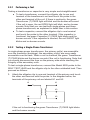
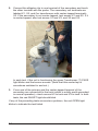
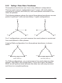
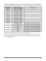
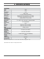
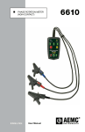
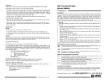
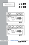
n
QUICK TESTER FOR
TRANSFORMERS AND
CAPACITORS
ENGLISH
User Manual
8505
Table of Contents
1. INTRODUCTION.................................................................................. 3
1.1 Receiving Your Shipment..........................................................3
1.2 Ordering Information.................................................................3
1.2.1 Replacement Parts.........................................................3
1.3 Introducing the Quick Tester Model 8505..................................4
2. OPERATION........................................................................................ 6
2.1 Performing a Self-Test...............................................................6
2.2 Testing Transformers and Capacitors........................................8
2.2.1 Performing a Test...........................................................9
2.2.2 Testing a Single-Phase Transformer..............................9
2.2.3 Testing a Three-Phase Transformer............................. 11
3. SPECIFICATIONS.............................................................................. 13
4. MAINTENANCE................................................................................. 14
4.1 Cleaning..................................................................................14
4.2 Repair......................................................................................14
4.3 Technical and Sales Assistance..............................................14
4.4 Limited Warranty.....................................................................15
4.5 Warranty Repairs.....................................................................15
2
Quick Tester Model 8505
1. INTRODUCTION
1.1 Receiving Your Shipment
Upon receiving your shipment, make sure that the contents are
consistent with the packing list. Notify your distributor of any missing
items. If the equipment appears to be damaged, file a claim immediately
with the carrier and notify your distributor at once, giving a detailed
description of any damage. Save the damaged packing container to
substantiate your claim.
1.2 Ordering Information
Quick Tester Model 8505.................................................... Cat. #2136.51
Includes a soft carrying case, probe, two alligator clips and a user manual.
1.2.1 Replacement Parts
Soft Carrying Case ..............................................................Cat. #2139.72
Probe.................................................................................... Cat. #5000.70
One Black Alligator Clip........................................................ Cat. #5000.71
Order Accessories and Replacement Parts Directly Online
Check our Storefront at www.aemc.com for availability
Quick Tester Model 8505
3
1.3 Introducing the Quick Tester Model 8505
The AEMC® Quick Tester Model 8505 is a hand-held instrument for
performing quick basic integrity tests on transformers and capacitors
used by electrical utilities. This instrument is a fast and inexpensive
inspection tool for detecting opens or shorts caused by shipping damage
or workmanship issues, and for verifying the proper operation of
switching components.
The Model 8505 verifies transformers with functional coils without
requiring a full transformer ratio test. A single user can check a shipment
of incoming transformers; units that have a defective coil or switch can
be quickly pinpointed and turned around for repair. The instrument
provides simple, single-button operation; the user only needs to make
the proper connections and push a button. Test results are clearly
indicated by bright LEDs and (when applicable) a buzzer. The instrument
includes captive cables with safety clips, test probe, and a built-in fuse
for protection; and operates on four AA batteries. It also automatically
detects whether or not the unit under test is a transformer or a capacitor.
The Model 8505 features internal multi-frequency ACV source and
loads to accommodate the testing of a wide range of transformers and
capacitors. Its microprocessor-based design provides a high level of
control, stability, and repeatability. Other Model 8505 features include
built-in self-test components, fuse protection, and an indicator providing
ample warning for low battery. Typical users include electrical utility
maintenance and management personnel at electrical utility supply and
transformer repair facilities. For instance, electrical utility staff can use
4
Quick Tester Model 8505
the Model 8505 to test an incoming shipment of transformers from the
manufacturer to determine whether or not to accept the shipment or
send it back due to damage. The Model 8505 can similarly test phase
compensation capacitors for basic operation.
The Model 8505 comes with a probe, two alligator clips, and a carrying
pouch (see the illustration on the previous page). The probe and the
alligator clip are threaded and must be screwed on to the cable.
The Quick Tester Model 8505 is a companion product to AEMC’s DTR®
Model 8510 transformer tester. The Model 8505 differs from the Model
8510 in that the Model 8510 provides more detailed information about
the unit under test, but requires more time to set up and obtain results.
For example, the Model 8505 can determine whether or not to accept or
reject the incoming transformer; the Model 8510 is then used when the
transformer is subsequently set up and installed for operation.
Quick Tester Model 8505
5
2. OPERATION
2.1 Performing a Self-Test
Before using the Model 8505, perform a short series of self-tests to
ensure the instrument is functioning properly.
1. Locate the Model 8505 SELF TEST LEAD, labeled at the top of the
instrument’s front panel.
2. Attach the probe to the SELF TEST LEAD by inserting the lead into
the probe. Screw the probe into the cable.
3. Attach one of the alligator clips to the other (unlabeled) lead.
6
Quick Tester Model 8505
4. With the probe and clip separated, press the TEST button in the
center of the Model 8505 front panel.
The red OPEN light should blink while the button is depressed.
Release the button.
5. Connect the alligator clip to the probe tip, and press the TEST button
again. The red SHORT light should blink while you hold down the
button.
6. Separate the probe from the clip. Insert the tip of the probe into the
terminal labeled SELF TEST (T), and then press the TEST button.
The green Transformer (T) PASS light should blink, and the buzzer
should emit a steady sound.
7. Insert the probe into the terminal labeled SELF TEST (C), and press
TEST. The green Capacitor (C) PASS light should blink, and the
buzzer should sound.
If any of the preceding tests fail to produce the response described
above, return the instrument to AEMC® for repair.
Quick Tester Model 8505
7
2.2 Testing Transformers and Capacitors
WARNING
Before performing a test on a capacitor or transformer, ensure it is
fully de-energized. Testing an energized transformer or capacitor is a
potential shock hazard to the user and may damage the Model 8505.
When using the Model 8505 to check the secondary side of
transformers, note that high voltage may be present on the primary
side. Be sure to avoid any contact with primary-side connections
that have not been fully de-energized.
The Model 8505 is designed for testing the integrity of transformers and
capacitors used in the power industry.
With the Model 8505, you can test:
●● Transformers that have newly arrived at your facility. During
transport, vibration and shock can result in the transformer coils
to short, open, or disconnect from the terminals. Although it’s
possible for a transformer turn ratio meter to test for integrity,
this type of instrument requires more time and labor to set up,
connect to the transformer, and perform the test. The Model 8505
can perform a very quick and simple integrity test, enabling you
to test multiple transformers in a short amount of time.
●● A transformer transported back to the repair facility. You can use
the Model 8505 to ensure that the basic continuity of all the coils
is intact before performing more detailed tests.
●● Capacitor terminals or plates that may be damaged. The Model
8505 can quickly determine whether or not a capacitor is still
functioning to determine whether more detailed tests and repairs
are necessary.
Note that if a transformer coil is partially damaged – for instance, some
internal turns have shorted but there is continuity as a coil – or if a
capacitor is partially damaged but is still functioning as a capacitor, the
Model 8505 will not detect an error. (A turn-ratio meter or a winding
resistance meter would be a more effective instrument for detecting this
condition.)
8
Quick Tester Model 8505
2.2.1 Performing a Test
Testing a transformer or capacitor is very simple and straightforward.
●● To test a transformer, connect the alligator clip to one end
terminal of the transformer’s coil and touch the probe to the
other end terminal of the coil. If there is continuity, the green
Transformer (T) PASS light will blink and the buzzer will sound.
If the coil is open, the red OPEN light will blink, and no buzzer
sounds. Note that you can test both single-phase and threephase transformers, as explained in detail later in this section.
●● To test a capacitor, connect the alligator clip to one terminal
and touch the probe to the other terminal. If the capacitor is
functional, the green Capacitor (C) PASS light blinks and the
buzzer sounds. If the capacitor is shorted, the red SHORT light
blinks and no buzzer sounds.
2.2.2 Testing a Single-Phase Transformer
In single-phase power transformers, the primary coil(s) are accessible
over the insulators (bushings); the secondary coil(s) are more easily
accessible over the tank. When a coil is checked, the green Transformer
(T) PASS blinks and the buzzer sounds if the coil is functioning. Note that
you should disconnect the fuse on the primary side while checking the
integrity of the secondary coils.
To test a single-phase transformer, connect the Model 8505 probe to the
SELF TEST LEAD and the alligator clip to the other unlabeled lead. Then
proceed as follows:
1. Attach the alligator clip to one end terminal of the primary and touch
the other end terminal with the probe. In the diagram below, the
terminals of the primary coil are labeled H1 and H2.
H1
X1
X3
H2
X2
If the coil is functioning the green Transformer (T) PASS light blinks
and the buzzer sounds.
Quick Tester Model 8505
9
2. Connect the alligator clip to one terminal of the secondary and touch
the other terminal with the probe. The secondary coil terminals are
labeled X1, X2, and (for transformers with center-tapped terminals)
X3. If the secondary is not center-tapped, test across X1 and X2. If it
is center-tapped, also test across X1 and X3, and X2 and X3.
In each test, if the coil is functioning the green Transformer (T) PASS
light blinks and the buzzer sounds. (Note that this center tap is
sometimes switched in and out.)
3. If one end of the primary and the center-tapped terminal of the
secondary are connected to the tank (which is solidly earth-grounded
in normal operation), check across H2 to tank and X3 to tank. In both
tests, the red SHORT light should blink.
If any of the preceding tests encounter a problem, the red OPEN light
blinks to indicate the test failed.
10
Quick Tester Model 8505
2.2.3 Testing a Three-Phase Transformer
Three-phase transformers can have many different configurations.
The two most common configurations are Y (wye), with each phase
connected to neutral; and Delta (Δ), with each phase connected to the
other two phases.
The following diagram shows the typical three-phase transformer access
points for primary Y (left) and secondary Y (right) configurations.
H2
X2
H0
X0
H1
H3
X1
X3
Primary Y
Secondary Y
For Y configurations, you must measure from each phase to neutral and
from each phase to other phases.
A typical Delta configuration for a three-phase transformer is shown
below:
H2
H1
X2
H3
Primary Delta (∆)
X1
X3
Secondary Delta (∆)
For Delta configurations, you must measure from each phase to other
phases. Note that in this configuration, if one coil is open, the Model
8505 can still perform tests because the other two coils may be intact
and there is a complete pathway.
Quick Tester Model 8505
11
The following table lists the expected results reported by the Model 8505
testing across pairs of terminals in Y and Delta transformer configurations.
Measurement
terminals
X1 to X0
X2 to X0
X3 to X0
X1 to X2
X2 to X3
X3 to X1
H1 to H2
H2 to H3
H3 to H1
H1 to H0
H2 to H0
H3 to H0
H1 to X1
H2 to X2
H3 to X3
H0 to X0
Result if coil is good
(indicator light blinks)*
Transformer (T) PASS
Transformer (T) PASS
Transformer (T) PASS
Transformer (T) PASS
Transformer (T) PASS
Transformer (T) PASS
Transformer (T) PASS
Transformer (T) PASS
Transformer (T) PASS
Transformer (T) PASS
Transformer (T) PASS
Transformer (T) PASS
Transformer (T) PASS
OPEN
Transformer (T) PASS
OPEN
Transformer (T) PASS
OPEN
SHORT
OPEN
Comments
If H0 and X0 are connected to each other
If H0 and X0 are not connected together
If H0 and X0 are connected to each other
If H0 and X0 are not connected together
If H0 and X0 are connected to each other
If H0 and X0 are not connected together
If H0 and X0 are connected to each other
If H0 and X0 are not connected together
*The buzzer sounds when the Transformer (T) PASS light blinks.
Note that if the Delta configured transformer is primary with a neutral
(H0), and if the secondary Y has a neutral (X0), they may be shorted in
some configurations.
12
Quick Tester Model 8505
3. SPECIFICATIONS
ELECTRICAL
Short
<20Ω
Open
>20Ω
Transformer
Capacitor
>1mH
Power Source
0.5uF; <1mF
4 x 1.5V AA (LR6) Alkaline batteries
Battery Life
More than 2500 ten second tests on a full charge
Low Battery
Indicator
Red LED blinks; approximately 100 tests can be
conducted when LED starts to blink
MECHANICAL
Dimensions
7.2" x 3.65" x 1.26" (182.9 x 92.7 x 32mm) w/o leads
Weight
(with battery)
14.4 oz. (408 grams)
Case
UL94
Vibration
IEC 68-2-6 (1.5mm, 10 to 55Hz)
Shock
IEC 68-2-6 (1.5mm 10 to 55Hz)
Drop
IEC 68-2-32 (1m)
ENVIRONMENTAL
Operating
Temperature
14° to 122°F (-10° to 50°C)
Storage
Temperature
-4° to 140°F (-20° to 60°C)
Relative Humidity
0 to 85% @ 95°F (35°C), non-condensing
Altitude
2000m
SAFETY
Safety Rating
50V CAT IV
Environmental
IP30
Reference Conditions: 23°C ± 3°C, 30 to 50% RH, battery voltage: 6V ± 10%.
*Specifications are subject to change without notice
Quick Tester Model 8505
13
4. MAINTENANCE
4.1 Cleaning
Disconnect anything connected to the device.
●● Use a soft cloth lightly moistened with soapy water. Wipe with a moist
cloth and then completely dry with a dry cloth.
●● Never use alcohol, solvents or hydrocarbons.
4.2 Repair
Ship To:Chauvin Arnoux®, Inc. d.b.a. AEMC® Instruments
15 Faraday Drive
Dover, NH 03820 USA
Phone: (800) 945-2362 or (603) 749-6434 (Ext. 360)
Fax: (603) 742-2346 or (603) 749-6309
E-mail:[email protected]
NOTE: You must obtain a CSA# before returning any instrument.
Costs for repair, standard calibration, and calibration traceable to N.I.S.T.
are available.
4.3 Technical and Sales Assistance
If you are experiencing any technical problems, or require any assistance
with the proper operation or application of your instrument, please call,
mail, fax or e-mail our technical support team:
Chauvin Arnoux®, Inc. d.b.a. AEMC® Instruments
200 Foxborough Boulevard
Foxborough, MA 02035 USA
Phone:(800) 343-1391 or (508) 698-2115
Fax: (508) 698-2118
E-mail:[email protected]
NOTE: Do not ship Instruments to our Foxborough, MA address.
14
Quick Tester Model 8505
4.4 Limited Warranty
The Quick Tester Model 8505 is warranted to the owner for a period
of one year from the date of original purchase against defects in
manufacture. This limited warranty is given by AEMC® Instruments, not
by the distributor from whom it was purchased. This warranty is void if
the unit has been tampered with or abused, or if the defect is related to
service not performed by AEMC® Instruments.
Full warranty coverage and product registration is available on our
website at www.aemc.com/warranty.html.
Please print the online Warranty Coverage Information for your records.
What AEMC® Instruments will do:
If a malfunction occurs within the one-year period, you may return the
instrument to us for repair, provided we have your warranty registration
information on file or a proof of purchase. AEMC® Instruments will, at its
option, repair or replace the faulty material.
REGISTER ONLINE AT: www.aemc.com
4.5 Warranty Repairs
What you must do to return an Instrument for Warranty Repair:
First, request a Customer Service Authorization Number (CSA#) by
phone or by fax from our Service Department (see address below), then
return the instrument along with the signed CSA Form. Please write the
CSA# on the outside of the shipping container. Return the instrument,
postage or shipment pre-paid to:
Ship To:Chauvin Arnoux®, Inc. d.b.a. AEMC® Instruments
15 Faraday Drive
Dover, NH 03820 USA
Phone:(800) 945-2362 or (603) 749-6434 (Ext. 360)
Fax: (603) 742-2346 or (603) 749-6309
E-mail:[email protected]
Caution: To protect yourself against in-transit loss, we recommend you
insure your returned material.
NOTE: You must obtain a CSA# before returning any instrument.
Quick Tester Model 8505
15
03/15
99-MAN 100408 v2
Chauvin Arnoux®, Inc. d.b.a. AEMC® Instruments
15 Faraday Drive • Dover, NH 03820 USA • Phone: (603) 749-6434 • Fax: (603) 742-2346
www.aemc.com