1
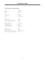
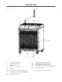
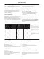
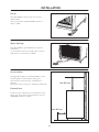
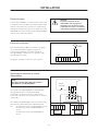
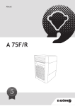
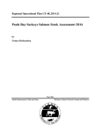
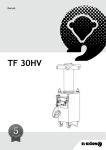
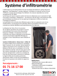
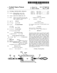
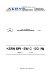
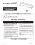
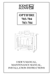
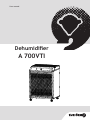
User manual
Dehumidifier
A 700VTI
-1-
-2-
INTRODUCTION
The A 700VTI is a dehumidifier intended for major
industrial dehumidification, for example, for drying
timber or other industrial drying processes. It can also
be used to keep storage facilities dry. Its dimensions
mean that it can efficiently dry around 15m³ of fresh
timber (soft wood) sufficiently for shipping (18%).
It can also dry 30-35m³ from around 20% down to
8% (carpentry dryness)
The instruction book describes all the necessary safety
details and must be read and understood by the user,
before the dehumidifier is connected to an electricity
supply. i.e. the first thing you must do is read this
instruction book.
There are symbols and warning marks in this
instruction book, and on the dehumidifier, which are
shown on the next page.
If any warning label on the dehumidifier has been
deformed or damaged, a new one must be ordered
and affixed on the machine as soon as possible in
order to ensure the greatest possible safety during
the use of the dehumidifier.
This instruction book provides a through description
of how the dehumidifier is to be used and looked
after, and how to carry out supervision.
This book also describes what action must be taken to
ensure maximum safety, and how these safety details
are formulated, as well as how they work.
The dehumidifier must only be used for the types of
work which are described in these user instructions.
IMPORTANT! The section on safety must be
read and understood by everyone who is to use
or repair the dehumidifier.
The manufacturer reserves the right to make
alterations to these instructions.
The instruction book covers the use and various
maintenance procedures which can be carried out
by the operator. More thorough servicing or error
detection must be carried out by the manufacturer’s
service personnel.
TABLE OF CONTENTS
Introduction ....................................................
3
Safety Instructions .........................................
4
Technical Data ................................................
5
Description .....................................................
6-9
Installation ......................................................
10-11
Dehumidification ...........................................
12
Maintenance ....................................................
13
Spare Parts ......................................................
14
Notes ...............................................................
15
Please read through this instruction manual carefully
and make sure you havefully understood its content
before using the machine.
-3-
SAFETY INSTRUCTIONS
Warning marks
Read through this instruction book
carefully and understand its contents
before you use this dehumidifier.
Warning and Important Note
In the text of these user instructions, the following
boxes are in relevant places.
Warning! This dehumidifier can become
dangerous! Careless or incorrect usage
may result in serious and even lifethreatening injury.
WARNING!
These boxes give warning of potential
personal injury or damage to property.
The warning boxes are placed in front
of the procedure to which they refer.
Warning: high voltage is present if the
cover is removed without the
dehumidifier being disconnected from its
VARNING!
power supply first.
400V
IMPORTANT!
These warning boxes set out actions which
facilitate a particular procedure, and any
special instructions.
The manufacturer’s guarantee on this
product fulfils the safety requirements of
the low-voltage directive.
Safety while setting up the machine
Safety during maintenance
Any fixed connection to an electricity supply and that
of any peripheral equipment must be carried out by a
qualified electrician.
Before any maintenance work is carried out on the
dehumidifier, the machine should be disconnected
from its power supply. This is done either by removing
the plug from the power point or by shutting off the
current using a circuit breaker.
Safety while using the machine
The dehumidifier’s air intake and air outlet must never
be covered during operation.
Protective covers and covering plates must never be
removed during operation.
All maintenance on the electrical system must be
carried out by a qualified electrician.
All maintenance on the cooling system must be carried
out by a qualified cooling installation engineer.
When cleaning the condenser, use gloves in order to
avoid cuts.
-4-
TECHNICAL DATA
Technical data of the dehumidifier
Width:
Height:
Depth:
1190 mm
1625 mm
890 mm
Weight:
Power supply:
Fuse:
300 kg
3N~400V
25 A, slow blow
Rated power:
Power consumption, compressor:
Power consumption, fans (2 pcs):
6800 W
6000 W
800 W
Working range, temp:
Working range, RH:
Dehumidifying capacity:
Air flow, free blowing:
+10 - +55°C
20-99%
max 30 l/h
9000m3/h
Refrigerant, type:
Refrigerant, quantity:
Pressure switch setting, low pressure:
Pressure switch setting, high pressure:
R134a
9000g
2,0 bar, diff=1,5 bar
23 bar
-5-
DESCRIPTION
P1
P2
P3
P4
2
S1 F1
GP01
1
GT03
3
4
1 Label ”Warning 400 V”
2
Classification panel
3Wheels
4 Water connection, R1”
AEV Vaporiser
GP01 Manual reset for pressure switch high pressure contact. (in the electrical box)
AEV
P1
P2
P2
P4
S1
Operation warning lamp, green.
High pressure warning lamp, red.
Low pressure warning lamp, red.
Hot gas thermostat trip warning lamp, red.
Start/stop switch.
F1 Control fuse (in the electrical box)
GT03 Hot gas thermostat
-6-
DESCRIPTION
Function
Dry air
M01, M02
The A 700VTI is a condensing dehumidifier and is
constructed on the principle that humidity in the air
condenses on cold surfaces.
The cold surfaces are created on the vaporiser (AEV)
by means of the compressor (M03) transferring heat
from the vaporiser to the condenser (KD).
The dehumidifier is provided with two fans (M01 and M02) which transport the air through the
dehumidifier.
First, the air passes the vaporiser (AEV), where the
moisture condenses and is deposited on the vaporiser.
The water is collected in a trough located under the
vaporiser, and is then led away.
After this, the air passes the condenser (KD) and
the fans (M01 and M02). In the condenser, the air is
heated at the same time as the condenser is cooled
down.
Moist air
KD
M3
AEV
Diagram showing principles of movement
Components
AEV
FT
GP01
Vaporiser
Drying filter
Pressure switch
KD
M03
MU
Condenser
Compressor
Test point
SD
SG
SV
GT03
TC
Regulator unit
Inspection window
Safety fuse
Hot gas monitor
Expansion valve
GT03
MU
M03
LP
GP01
7/8”
AEV
MU
KD
HP
1 1/8”
GP01
TC
MU
1/2”
1/2”
FT
SV
-7-
MU
1/2”
SG
SD
DESCRIPTION
Electrical system
Operation warning lamp (P1)
Control fuse (F1)
H1 is lit when the following conditions are met:
• The dehumidifier is powered.
• The phase sequence relay approves the connection.
• Any external control is shut off.
The circuit breaker, F1, breaks the current at 6A
and protects the dehumidifier’s control systems.
Hot gas monitor (GT03)
Protects the compressor from overheating.
High pressure warning lamp (P2)
If it gets too hot during operation
(maximum surrounding temperature 55°C), the
pressure in the condenser rises and the high pressure
contacts in the pressure switch (GP01) are triggered.
The high pressure warning lamp (P2) lights up and
the dehumidifier stops.
GP01 is reset manually using the reset button on the
pressure switch.
Low pressure warning lamp (P3)
P3 is lit when the following conditions are met:
• The low pressure in the vaporiser is below the selected value.
(2.0 bar, ∆p=1.5 bar)
• S1 is in position ”1”.
• The phase sequence relay approves the connection.
• Any external control is shut off.
Hot gas thermostat warning lamp (P4)
(P4) flashes when the hot gas thermostat has been
triggered. The dehumidifier’s built-in relay, K7, causes
lamp P4 to flash for as long as the thermostat is
triggered.
When the hot gas thermostat is reset, lamp P4 stays
lit. Relay K6 is self-regulating and is reset by switching
the dehumidifier off and on using S1.
On/Off switch (S1)
Fans (M01 and M02)
Each of the fan motors are provided with a thermocontact, GT01 and GT02. The thermo-contacts are
inside the motor coils and break the current when the
temperature is raised. The thermo-contacts are reset
automatically when the temperature has decreased.
Time relay (K8)
The time relay, K8, is time-delayed and can be set to
a value between 0 and 300 seconds. In order to avoid
major instantaneous surges in current at the start
of operation, where several dehumidifiers are being
governed from the same starting point, the time relays
on the different dehumidifiers are set for different
times, e.g. 10 seconds apart.
When the A 700VTI is being used at lower
surrounding temperatures, K8 is set to a start delay
of 300 seconds, see page 9 under Pressure Switch
(GP01), Industrial Dehumidifier.
Phase sequence relay (K4)
The phase sequence relay detects whether all phases
arecorrectly connected, so that the motors turn in the
right direction.
In the case of an incorrect connection, the phase
sequence relay stops the supply of current to the
dehumidifier’s control systems, and the machine
cannot be started.
Control switch
-8-
DESCRIPTION
Pressure Switch (GP01)
GP01 is a double pressure switch for low and high
pressure. The low pressure contact starts the
compressor when the pressure in the vaporiser reaches
2.0 bar, and stops at 0.5 bar.
The high pressure contact stops the compressor when
the temperature densor rises so that the pressure
exceeds 23 bar. The high pressure contact is reset
manually using GP01.
Cut in = 2 bar and Cut out = 0.5 bar.
These settings are adjusted according to the
surrounding temperature, Tsurr, and are tested where the
machine is currently operating.
In order to reduce the risk of an interruption in
operation at surrounding temperatures under
25°C, Tsurr should be constant.
See table 1 for the guideline value for the pressure
switch's low pressure at different surrounding
temperatures.
Please note that the table only specifies guideline
values and may differ between machines and where
the machines are currently being used.
The Cut in should not exceed 3 bar and the Cut out
should not go below 0 bar. In order to ensure the
smooth operation of the compressor, the time relay,
K8, is also adjusted to a start delay of 5 minutes,
see table 1.
Industrial Dehumidifier
When using the A 700VTI at when the surrounding
temperature, Tsurr, is lower than around 25°C, it is
necessary to optimise the defrosting cycle and
operation by adjusting and adapting the low pressure
values (Cut in, Cut out) in the double pressure switch
GP01.
If no ice is being formed on the vaporiser, this is not
necessary, and then the factory setting is recommended,
Tsurr [°C]
Cut in [bar]
10
11
12
13
14
15
16
17
18
19
20
21
22
23
Cut out [bar]
1.2
1.3
1.4
1.4
1.5
1.6
1.7
1.8
1.9
2.0
2.1
2.3
2.4
2.5
Tid på K8 [s]
0
0
0
0
0
0.1
0.2
0.3
0.4
0.5
0.5
0.5
0.5
0.5
External control
The dehumidifier is designed to be connected to various
systems.
X1:24 & X1:25
External control (230V AC)
Enables external start (closed contact) and stop (open
contact).
E.g. Hygrostat control
Looped on delivery.
X1:6 & X1:7
External control (230V AC)
Enables external control of the dehumidifier, with
monitoring circuits in operation.
Looped on delivery.
300
300
300
300
300
300
300
300
300
300
300
300
300
300
Table 1
Guideline values for adjusting
the pressure switch's low pressure
values, Cut in and Cut out,
during operation at surrounding
temperatures, Tsurr , lower than
25°C.
Please note that the table only
specifies guideline values and may
differ between machines and where
the machines are currently being
used.
X1:11 & X1:12
External control (230V AC)
Enables external control of electrical heating (accessory).
Looped on delivery.
X1:13 & X1:N
Control voltage (230V AC) for electrical heating
(accessory).
X1:20 & X1:21
External control (230V AC)
Enables external control of the compressor (only).
Looped on delivery.
Operational status (signal lamps P1 - P4) can be taken
from plinths X1:31 (P1), X1:32 (P2), X1:33 (P3) and
X1:34 (P4).
-9-
INSTALLATION
Set-up
The dehumidifier can be set up on a flat and stable surface.
After set-up, check the dehumidifier’s wheels so
that it is stable.
Water drainage
The dehumidifier is provided with an outlet for
connection.
to a water drain. Connect the pipe (R1”) so that it
feeds down to a floor drain or similar.
Air circulation
The appropriate place for the dehumidifier is with its back against a wall inside the drying area.
The free area in front must be a minimum of 400 mm.
The free area above must be a minimum of 800 mm.
Min 800 mm
External fans
If there are any other fans for air circulation in the
drying area, these must not blow directly onto the
dehumidifier’s inlets or outlets.
Min 400 mm
- 10 -
INSTALLATION
Electrical supply
WARNING!
Electrical connection of the
dehumidifier and its peripheral
equipment must be carried out by
a qualified electrician in accordance
with national installation regulations.
Connect the humidifier via a main switch to 3N~400
V and protective earth (PE). The mains shall be fused
with 25 A slow blow fuse. Connect to terminal (X1).
The phase-sequence relay (K4) is activated only if the
dehumidifier is correct connected. If the dehumidifier
will not start, switch two phases.
Electrical connection
% RH
External humidistat (%RH) for automatic stopping
An external humidistat regulates compressor
Connect the humidistat to terminal 24 and 25.
The dehumidifier compressor is in operation with
closed hudistat contacts.
X1
24 7
25
6
See page 9 “external control” for more options.
Simultaneous operation of several
dehumidifiers
~
NOTE!
The figure to the right shows only parallel
operation for two dehumidifiers.
ManöverExternal
start/stop
kontakt
To control several dehumidifiers at the same time
the appropriate pair of terminals should be
connected to an external contactor. The control
coil of the contactor is to be connected to a external
control (RC).
To avoid that all dehumidifiers start at the same time,
the time relays (K8) shall be set at different times.
Set; the time relay in the 1:st dehumidifier to 0 sec.
the time relay in the 2:nd dehumidifier to
10 sec.
the time relay in the 3:rd dehumidifier to
20 sec.
- 11 -
X1
X1
24 25
K8=0 s
Dehumidifier 1
24 25
K8=10 s
Dehumidifier 2
DEHUMIDIFICATION
Motor protection compressor trigger P4 lights up/flashes
WARNING!
The dehumidifier's air intake and air
outlet must never be covered during
use. Protective covers and covering
plates must never be removed during
use.
If the compressor stops, this means that the
compressor is too hot. Lamp P4 flashes for as long
as the compressor's built-in overheating protection
system has been triggered.
Once the compressor has cooled down, the built-in
protection is reset automatically and lamp P4 stays lit.
After this, the dehumidifier can be reset using S1.
(Alarm P4 is rest by switching the dehumidifier off
and on again using S1)
The dehumidifier extracts moisture from the air at
temperatures between +10 - +55 °C.
Connect the dehumidifier.
Start the dehumidifier with the start switch (S1).
The operation warning lamp P1 will light up.
Switch off the dehumidifier with the start/stop
switch (S1).
The dehumidifier is completely deactivated - all lamps off
IMPORTANT!
The maximum temperature allowed during
dehumidification is 55°C. If the
temperature rises higher than this, the high
pressure protection system (GP1) is triggered.
If none of the lamps are lit, and the dehumidifier
is completely deactivated, despite being correctly
connected to a power supply (including phase
sequence), it means that the fuse (F1) has blown.
Reset the fuse as follows:
High pressure trigger - P2 lights up
If the dehumidifier stops and the high pressure lamp
(P2) lights up, the high pressure protection system
on the pressure switch (GP01) has been triggered.
Once the dehumidifier has cooled down (maximum
surrounding temperature 55°C), the protection system
is rest by pressing the reset button.
1.
2.
3.
4.
5.
Disconnect the dehumidifier's electrical connection. (plug or circuit breaker)
Unscrew the lid on the electrical box.
Identify and isolate the cause of fuse F1 tripping.
Reset the fuse (F1).
Replace the lid and start the dehumidifier.
Comments: The circulation fans have a built-in overheating
protection system that resets itself.
Low pressure trigger - P3 lights up
If the dehumidifier stops and the low pressure lamp,
P3, lights up, either the surrounding temperature is
too low, or the amount of cooling medium is too
small - in the latter case, call the cooling technician.
Defrosting
At lower surrounding temperatures, where ice forms
on the vaporiser, see page 9 under Pressure Switch
(GP01), Industrial Dehumidifier.
- 12 -
MAINTENANCE
WARNING!
Before any maintenance work is carried out on the dehumidifier, the machine should be
disconnected from its power supply.
This is done either by removing the plug out of its power point or by means of shutting off the
current with the help of a circuit breaker.
All maintenance on the electrical system must be carried out by a qualified electrician.
All maintenance on the cooling system must be carried out by a qualified cooling installation
engineer.
Every month
Repairs
Check every month to see that the dehumidifier is
clean inside.
In the case of comprehensive repairs, contact
your retailer.
WARNING!
Use gloves when working on the
condenser. There is a danger of
receiving cuts from the sharp grille
slats.
During the guarantee period, the retailer must
always be contacted before any repairs are carried out.
Carry out the following actions whenever necessary:
• Clean the vaporiser cooling pipes with water.
• Blow-clean other equipment with compressed air.
IMPORTANT!
Never point the flow of compressed air
directly towards the grille slats on the
condenser. These can be damaged by a blast of
compressed air.
- 13 -
SPARE PARTS
When ordering spare parts, always quote:
• Type
• Serial Number
Pos shows where the spare part is in the diagram.
This information can be found on the top row of the
dehumidifier's classification panel (see page 3)
Page(s) shows on what page(s) the diagram in
question can be found.
Number shows how many units of the current spare
part are to be found in the dehumidifier.
Pos
Page(s)
Name Number Catalogue No.:
1
3
AEV
F1
FT
GP01
GT03
P1
P2-4
K1
Q2
Q3
K4
K5
K6
K7
K8
KD
5
5
5,6
7,15
6
Label ”Warning 400V”
Wheels
Dehumidifier package
Fuse, Small circuit breaker B6A
Drying filter
6,7,16
6,7,12
5,7,16
5,7,16
16
15,16
15,16
7,15,16
16
16
16
16
6
Pressure switch, double 1
Hot gas monitor 1
Warning lamp, green 1
Warning lamp, red 3
Connection box 1
Connection box 1
Connection box 1
Phase sequence relay 1
Relay1
Time relay 1
Time relay 1
Time relay 1
Condenser 1
1
4
1
1
1
M01-027,15
Fan 2
M03 6,15,16Compressor1
SG
6
Inspection window 1
- 14 -
KL604236
KL504210
KLA400665
2110106
KL401330
KL404015
KL304240
KL302203
KL302202
3230604
3233024
3232174
KL301007
4027857
4036440
KL301407
4079150
KL400570
KL300004
KLA410300
KLA402020
NOTES
.................................................................................................................................................................................................................
.................................................................................................................................................................................................................
.................................................................................................................................................................................................................
.................................................................................................................................................................................................................
.................................................................................................................................................................................................................
.................................................................................................................................................................................................................
.................................................................................................................................................................................................................
.................................................................................................................................................................................................................
.................................................................................................................................................................................................................
.................................................................................................................................................................................................................
.................................................................................................................................................................................................................
.................................................................................................................................................................................................................
.................................................................................................................................................................................................................
.................................................................................................................................................................................................................
.................................................................................................................................................................................................................
.................................................................................................................................................................................................................
.................................................................................................................................................................................................................
.................................................................................................................................................................................................................
.................................................................................................................................................................................................................
.................................................................................................................................................................................................................
.................................................................................................................................................................................................................
.................................................................................................................................................................................................................
.................................................................................................................................................................................................................
.................................................................................................................................................................................................................
.................................................................................................................................................................................................................
.................................................................................................................................................................................................................
- 15 -
- 16 -
KL597022-GB /141024
El-Björn AB, Box 29, 334 21 Anderstorp
Tel: 0371-588 100, Fax: 0371-181 34
[email protected], www.elbjorn.com