1
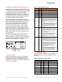
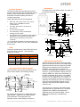
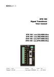
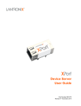
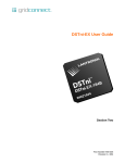
XPort® Embedded Device Server Data Sheet
General Description
The Lantronix® XPort® embedded device server is
the most compact, integrated solution available to
web-enable any device with a serial interface. By
simply adding an XPort unit to a product design,
device manufacturers cut their design cycle by as
much as 80% and are able to offer Ethernet
connectivity in record time.
x
The XPort module offers the highest level of
integration available in a device server. Within a
compact RJ45 package is a DSTni® EX 186
controller, memory, 10/100 Ethernet transceiver,
high-speed serial port, status/diagnostic LEDs, and
3 programmable I/O pins. In the space that is
normally consumed by a connector, the XPort unit
provides a complete networking interface.
To enable access to a local network or the Internet,
the XPort module integrates a fully developed
TCP/IP network stack and OS. The XPort unit also
includes an embedded web server used to remotely
configure, monitor, or troubleshoot the attached
device.
910-815I XPort Embedded Device Server Data Sheet
Where there’s a need for custom user interfaces
and a desire to use common and familiar tools, the
XPort module can serve web pages to a web
browser. The XPort unit becomes a conduit
between you and your device over the network or
Internet.
The Lantronix DeviceInstaller™ utility is a Windows
based configuration tool that simplifies installation
and setup. The XPort module can also be set up
locally through its serial port, or remotely over a
network using Telnet or a web browser. Flash
memory provides for maintenance-free nonvolatile
storage of web pages, and allows future system
software upgrades.
Using our highly integrated hardware and software
platform, you will add profit to your bottom line by
significantly reducing product development time,
risk, and cost.
Key Features
• The only complete, integrated solution in an RJ45
form factor
• Complete integrated solution
• Embedded web server
• 10/100Mbit Ethernet – Auto-Sensing
• Stable, field proven TCP/IP protocol suite and webbased application framework
• Easy configuration through a web interface
• Easy customization of HTML web pages and
configuration screens
• Interactive web pages through the use of Java
applets
• E-mail
• 128-, 192-, or 256-bit AES Rijndael encryption
(Optional)
• EMI tested and compliant
• Extended operating temperature:
-40 to +85˚ C normal mode
-40 to +75˚ C high-performance mode
• High-performance processor
(12 MIPS at 48 MHz, 22 MIPS at 88 MHz)
• Network overhead handled by XPort unit
• Password protection
• Upgrade XPort module’s firmware over the network
• 3.3V power
• Serial-to-10/100 Ethernet conversion
• 921,600 baud serial speed
Copyright© 2014, Lantronix. All rights reserved.
Hardware & Software Description
The XPort unit is a complete solution (hardware and
software) for web-enabling your edge devices. Packed
into an RJ45 connector smaller than your thumb, this
powerful device server comes with a 10BASET/100BASE-TX Ethernet connection, a reliable and
proven operating system stored in flash memory, an
embedded web server, a full TCP/IP protocol stack,
and standards-based (AES) encryption.
The XPort software runs on a DSTni EX controller
which has 256 KB of SRAM, 16 KB of boot ROM, and
a MAC with integrated 10/100BASE-TX PHY. The
XPort module communicates to the edge device
through a 3.3V serial interface and three generalpurpose programmable I/O pins. 512 KB of flash
memory is included for storing firmware and web
pages. The XPort runs on 3.3V, and has a built-in
voltage supervisory circuit that will trigger a reset if the
supply voltage drops to unreliable levels (2.7V). A
built-in 1.8V regulator drives the processing core of
the EX controller.
Table 1 - PCB Interface Signals
Signal
Name
Pin
GND
1
Circuit Ground
Vcc
2
+3.3V Power In
Reset (In)
3
External Reset In
Data OUT
4
Serial Data Out
Data IN
5
Serial Data In
CP1 can be configured as follows:
CP1
6
FLASH
Tx
Rx
CP2 can be configured as follows:
CP2
7
CMOS IO RESET
CP3 can be configured as follows:
• Flow control: CTS (Clear to Send)
input read by DSTni’s built-in UART for
connection to RTS of attached device.
CP3
8
RJ45
DSTni EX
Ethernet Interface
The 10/100 Ethernet magnetics, network status
LEDs, and RJ45 connector are integrated into the
XPort unit.
Table 2 - Ethernet Interface Signals
Signal Name
TX+
DIR
Out
Contact
1
TX-
Out
2
RX+
In
3
Receive Data +
RX-
In
6
Receive Data –
Primary Function
Transmit Data +
Transmit Data –
Not Used
4
Terminated
Not Used
5
Terminated
Not Used
7
Terminated
Not Used
8
Terminated
SHIELD
910-815I XPort Embedded Device Server Data Sheet
• Modem control: DCD (Data Carrier
Detect) input read by DSTni’s built-in
UART for connection to DTR of
attached device.
• Programmable input/output: CP3 can
be driven or read through software
control, independent of serial port
activity.
+3.3VDC
PCB Interface
The 8-pin PCB interface consists of 3.3V CMOS
Serial In/Out, 3 Flow Control/Handshake/PIO pins,
reset input, +3.3V power, and signal ground. The
serial pins and CP pins are 5V tolerant. RESET and
Power are 3.3V tolerant.
• Modem control: DTR (Data Terminal
Ready) output driven by DSTni’s builtin UART for connection to DCD of
attached device.
• Programmable input/output: CP2 can
be driven or read through software
control, independent of serial port
activity.
LEDs
25MHz
• Flow control: RTS (Request to Send)
output driven by DSTni’s built-in UART
for connection to CTS of attached
device.
• Programmable input/output: CP1 can
be driven or read through software
control, independent of serial port
activity.
An RJ45 Ethernet cable connects directly into an
XPort unit. Ethernet magnetics, status LEDs, and
shielding are built in. The XPort module was designed
to meet class B emissions levels, which makes the
electromechanical integration very simple.
MAGNETICS
Function
Chassis Ground
Copyright© 2014, Lantronix. All rights reserved.
Protocol Support
The XPort module uses Internet Protocol (IP) for
network communications and Transmission Control
Protocol (TCP) to assure that no data is lost or
duplicated, and that everything sent arrives
correctly at the target.
Dimensions
The dimensions of the XPort module are shown in
the following drawings:
18.25 [0.719]
FRONT
VIEW
16.25 [0.640]
DIMS = mm (in)
11.55 [0.455]
Other supported protocols are listed below:
•
•
•
•
•
7.15 [0.281]
ARP, UDP, TCP, ICMP, Telnet, TFTP, AutoIP,
DHCP, HTTP, and SNMP for network
communications.
TCP, UDP, and Telnet for connections to
the serial port.
TFTP for firmware updates.
IP for addressing, routing, and data block
handling over the network.
User Datagram Protocol (UDP) for typical datagram
applications in which devices interact with other
devices without maintaining a point-to-point
connection.
* For a complete discussion of protocol support, see
the XPort user manual for the XPort embedded
device server.
LEDs
The device contains two bi-color LEDs built into the
front of the XPort connector. (See dimension
drawing for location.)
Link LED (Left Side) Activity LED (Right Side)
Color
Meaning Color
Meaning
Off
No Link
Off
No Activity
Amber
10 Mbps
Amber
Half-Duplex
Green
100 Mbps
Green
Full-Duplex
Recommended PC Board Layout
The hole pattern and mounting dimensions for the
XPort unit are shown in the following drawing:
O 0.90 O
[ 0.035]
O 3.25 O
[ 0.128]
16.05
[0.632]
1.27 [0.050]
8
FRONT
12.30
[0.484]
SHIELD TAB
O 1.60[ 0.063]
7
2.54 [0.100]
DIMS = mm (in)
3.58 [0.141]
2
1
10.84 [0.427]
2.54 [0.100]
TOLERANCE
.XX+/-0.05[0.002]
6.35 [0.250]
11.90 [0.468]
For proper heat dissipation, the PCB should have
approximately 1 square inch of copper attached
to the shield tabs. The shield tabs are an
important source of heat sinking for the device.
910-815I XPort Embedded Device Server Data Sheet
LEFT
LED
RIGHT
LED
CONTACT 8
CONTACT 1
14.50 [0.571]
4.03 [0.158]
5.85 [0.230]
13.50 [0.531]
SHIELD TAB
1.27 [0.050]
TOLERANCE
0.40 [0.016]
.XX+/-0.20[0.008]
SHIELD TAB
3.30 [0.130]
1.85 [0.073]
3.25 [0.128]
1.00 [0.039]
33.90 [1.335]
INTERFACE
PINS
FRONT
SHIELD
GROUND
0.60 [0.024]
SHIELD TAB
0.35 [0.014]
10.84 [0.427]
2.54 [0.100]
TOLERANCE
.XX+/-0.20[0.008]
3.20 [0.126]
6.35 [0.250]
11.90 [0.468]
DIMS = mm (in)
OEM License Agreement
With the purchase of an XPort module, the OEM
agrees to terms and conditions of an OEM License
Agreement whereby Lantronix grants to the OEM
(subject to the complete terms and conditions of
the OEM License Agreement) a limited, nonexclusive, non-transferable, royalty-free, revocable
license to (i) use the software in object code form
solely for OEM’s use, without any modification, on
the XPort embedded device server, or for OEM’s
internal use in the development and integration of
the XPort unit with OEM’s products, (ii) market or
sublicense the software as a part of a combination
of the XPort unit with OEM’s products, and (iii)
reproduce and distribute the software in object
code form only.
The foregoing is a summary of the OEM License
Agreement and is not intended to be a complete
substitute for the OEM License Agreement.
Additional terms and conditions apply. The full
OEM License Agreement is available from
Lantronix.
Copyright© 2014, Lantronix. All rights reserved.
XPort Technical Data
Category
CPU, Memory
Firmware
Reset Circuit
Serial Interface
Serial Line Formats
Modem Control
Flow Control
Programmable I/O
Network Interface
Compatibility
Protocols Supported
LEDs
Management
Security
Internal Web Server
Weight
Material
Temperature
Relative Humidity
Shock/Vibration
Warranty
Included Software
Emissions
Immunity
Description
Lantronix DSTni EX 186 CPU, 256 KB zero wait state SRAM 512 KB Flash, 16 KB Boot ROM
Upgradeable via TFTP and serial port
Internal 200ms power-up reset pulse. Power-drop reset triggered at 2.6V. External reset input causes an internal
200 ms reset.
CMOS (Asynchronous) 3.3V-level signals. Rate is software selectable (300 bps to 921600 bps)
7 or 8 data bits, 1-2 Stop bits, Parity: odd, even, none
DTR/DCD, CTS, RTS
XON/XOFF (software), CTS/RTS (hardware), none
3 PIO pins (software selectable) sink or source 4mA max.
RJ45 Ethernet 10BASE-T or 100BASE-TX (auto-sensing)
Ethernet: Version 2.0/IEEE 802.3
ARP, UDP/IP, TCP/IP, Telnet, ICMP, SNMP, DHCP, BOOTP, TFTP, Auto IP, and HTTP
10BASE-T & 100BASE-TX Link Activity, Full/half duplex. Software generated status & diagnostic signals can
optionally drive external LEDs through CP1 & CP3 (see Int. Guide).
Internal web server, SNMP, Serial login, Telnet login
Password protection, locking features, optional Rijndael 128-, 192-, or 256-bit encryption
Serves web pages
Storage capacity: 384 KB
9.6 grams (0.34 oz)
Metal shell, thermoplastic case
Extended Temp RoHS product: -40°C to +85°C (-40°F to 185°F)
Storage range: -40°C to +85°C (-40°F to 185°F)
Operating: 5% to 95% non-condensing
Non-operational shock: 500 g's, Non-operational vibration: 20 g's
2-year limited warranty
Windows based DeviceInstaller configuration software & Windows based Com Port Redirector
Supported Windows OS
• x86 based Platforms: XP/2003 Server/Vista/Windows 7/Windows 8/2008 Server
• x64 based Platforms: Vista/Windows 7/Windows 8/2008 Server
FCC Part 15 Subpart B
Industry Canada ICES-003 Issue 4 February 2004
CISPR 22: 2005 Information Technology Equipment
VCCI V-3/200904
AS/NZS CISPR 22: 2006
EN 55022: 2006 +A1:2007
EN 61000-3-2:2006
EN 61000-3-3: 2008
EN 55024: 1998 +A1: 2001 +A2: 2003
EN 61000-4-2: 1995 + A2: 2001
EN 61000-4-3: 2006 + A1: 2008
EN 61000-4-4: 2004
EN 61000-4-5: 2006
EN 61000-4-6: 2007
EN 61000-4-8: 1994 + A1:2001
EN 61000-4-11: 2004
Recommended Operating Conditions
Parameter
Supply Voltage
Supply Voltage Ripples
Power Reset Threshold
RESET Pin Input Low Voltage
RESET Pin Input High Voltage
CPx, RX Input Low Voltage
CPx, RX Input High Voltage
CPx, TX Output Low Voltage
CPx, TX Output High Voltage
Input Leakage Current
Supply Current (idle)@ 48 MHz
Supply Current (10BASE-T activity)@ 48 MHz
Supply Current (10BASE-T activity)@ 88 MHz
Supply Current (100BASE-T activity)@ 48 MHz
Supply Current (100BASE-T activity)@ 88 MHz
910-815I XPort Embedded Device Server Data Sheet
Symbol
VCC
VCC PP
Min
Typical
Max
Units
3.14
3.3
3.46
2.0
Vdc
%
Vdc
Vdc
Vdc
Vdc
Vdc
Vdc
Vdc
µA
mA
mA
mA
mA
mA
2.7
VRES IL
VRES IL
VCP_IL
VCP_IH
VCP OL
VCP OH
II
ICC
ICC
ICC
ICC
lCC
0.36
3.46
0.8
5.5
0.4
2.0
2.0
2.4
1
119
224
267
190
233
Copyright© 2014, Lantronix. All rights reserved.
Development Kit
Introduction
A development kit for the XPort embedded device
server is available to provide a simple, quick, and
cost-effective way to evaluate the XPort unit. Use
the development kit to integrate the XPort module
to your product design, and give your newly
networked product a test drive.
Block Diagram
•
•
•
•
TP8
PIO
TP9
+5
VDC
IN
3.3V
J1
POWER
RTS
DTR
CTS/DCD
LEDs
Features of the Development Kit
•
D2
PWR
LED
JP4
TP13
TP11
SLOW
TMR
Complete, ready to use XPort unit and
supporting evaluation board
+5VDC Universal Power Supply
RS-232 cable, DB9M/F
CAT5e UTP RJ45M/M Ethernet cable
Serial adapter, 25-pin to 9-pin
DB-9F
RXD/TXD
XPort
RESET
RESET
SWITCH
SW2
PLD
DIP
SWITCH
RS232
DTR, CTS
RTS, DCD
PADS
JP3
PLD HEADER
SW1
Features of the Evaluation Board
The evaluation board for the XPort unit includes an
XPort module integrated with the following features:
•
•
•
•
•
•
•
RS-232 (DCE) serial interface
DIP switch configuration
LED indication for power, RS-232 transmit /
receive and PIO status
Reset circuit with pushbutton
Header connector for the PIO signals CP1,
CP2, and CP3
Test points to monitor the XPort unit’s serial
interface signals
Timer
Ordering Information
XPort XE
XP1001000-05R
Standard XPort module
Min. order: 50 units
XPort SE
XP1002000-05R
Standard XPort module with
256-bit AES encryption
Min. order: 50 units
XPort SE SMPL
XP100200S-05R
XPort Sample with encryption
One XPort module enclosed
XPort Dev. Kit
XP10010NMK-01
XPort Development Kit with
encryption
XP1002000-05R
For details contact your local Lantronix representative or Lantronix directly:
Asia Pacific Region via e-mail at [email protected]
Europe via e-mail at [email protected]
Japan via e-mail at [email protected]
United States via e-mail at [email protected] or call OEM sales support at 800-526-8764
©2014 Lantronix, Inc. All rights reserved. Lantronix, XPort, with its patented technology (US Patents 6,881,096, 7,018,242;
8,010,789; 8,788,814;), and DSTni are registered trademarks and DeviceInstaller is a trademark of Lantronix, Inc. All other
trademarks are the property of their respective owners. Specifications subject to change without notice. All rights reserved.
910-815I XPort Embedded Device Server Data Sheet
Copyright© 2014, Lantronix. All rights reserved.