1
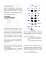
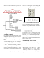
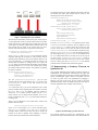
Authoring Graphics-Rich and Interactive Documents in
CGLIB – A Constraint-based Graphics Library
1
Neng-Fa Zhou
CUNY Brooklyn College & Graduate Center
2900 Bedford Ave., New York, NY 11210
[email protected]
http://www.sci.brooklyn.cuny.edu/~zhou
ABSTRACT
CGLIB is a high-level graphics library for B-Prolog, a constraint
logic programming system. The library provides primitives for
creating and manipulating graphical objects and a set of
constraints including non-overlap, grid, table, and tree constraints
that facilitates the specification of the layouts of objects. The
library adopts a construct called action rules available in B-Prolog
for creating agents and programming interactions among agents or
between agents and the user. The library is a fully working system
implemented in B-Prolog, Java and C. It can be used in many
areas such as drawing editors, interactive user interfaces,
document authoring, animation, information visualization,
intelligent agents, and games. The high-level abstraction of the
library and the use of constraints and action rules in the
specification of layouts and behaviors can significantly enhance
the productivity of the development of graphics. We demonstrate
through several examples the effectiveness of the library as a tool
for developing graphics-rich and interactive user interfaces.
General Terms
Documentation, Design, Languages.
Keywords
Programming languages, Constraints, Graphics programming,
Graphical user interface design, Agents, Action rules, Prolog.
1. INTRODUCTION
The widespread use of window systems has made a graphics
package indispensable for any programming languages [9]. Prolog
and CLP (Constraint Logic Programming) languages in general
are not an exception. Some efforts have been made to introduce
graphics programming into CLP. One widely used approach is to
1
This research was supported by grants from PSC CUNY,
CUNY Software Institute, and ONR (#N00014-96-1-1057).
adopt an external interface with a language that supports graphics
programming. For example, JIPL is an interface developed by
Kino [8] that bridges Prolog and Java bi-directionally. Any Prolog
system that adopts the interface will be able to access the graphics
library of Java. This approach is not satisfactory for the following
two reasons. First, the programmer has to write code in two
languages. This is especially daunting when there are interactions
involved. Second, the graphics library in the adopted language,
whether it is C, C++, Java, VB, or Tcl/Tk, is at such a low level
that it does not match well with a high-level language like Prolog.
CLP languages deserve a high-level graphics library that can be
used to specify easily the states, layouts, and behaviors of
graphical objects.
Motivated by the observations, we designed and implemented a
high-level and constraint-based graphics library, called CGLIB,
for B-Prolog. The library provides primitives on graphical objects
and provides various kinds of constraints that facilitate the
specification of the layouts of graphical objects. The constraint
solver of B-Prolog serves as a general-purpose layout manager
that is significantly more flexible than the special-purpose layout
managers used in Java and Tcl/Tk. The library adopts a construct
called action rules available in B-Prolog for programming
interactions. An action rule consists of a pattern for agents, a
pattern for events that can activate the agents, and an action the
agents carry out when activated. Agents can communicate with
each other through logical or global variables. Agents can behave
concurrently and sequentially as well.
CGLIB is implemented in B-Prolog, Java, and C. CGLIB enables
the user to use the Java graphics package without the need to
write any code in Java. CGLIB, however, is not just another
syntax sugar for Java’s graphics package. It has a significantly
higher abstraction level and is much easier to learn and use than
Java’s graphics package. One of the distinguishable features of
CGLIB is the use of constraints in the specification of layouts. In
graphics languages such as PostScript and Tex, the programmer
has to specify every single detail about the graphical objects,
including their sizes and positions. In languages such as Java and
Tcl/Tk, the layout managers help determine the layouts of objects
for certain applications, but the layout algorithms lack flexibility
and are difficult to learn and use. The use of constraints
significantly relieves the burden of the programmers to describe
many tedious details about layouts. Another distinguishable
feature of CGLIB is its support of action rules for specifying
interactions. Action rules can be used to describe and synchronize
sophisticated and dynamic behaviors of graphical objects in a
simple and straightforward manner.
CGLIB can be used in many areas such as drawing editors,
interactive user interfaces, document authoring, animation,
information visualization, intelligent agents, and games. In this
paper, we describe the library and present several sample
applications.
Familiarity with logic and constraint programming concepts is
assumed, but most of the material should be readable for readers
who don’t have any programming experience in Prolog or CLP.
The reader is referred to [3] for the basics.
2. THE CGLIB
2.1 An Illustrative Example
Let us start with the following program:
go:cgButton(B),
B^text #= “Hello World”,
handleButtonClick(B),
cgShow(B).
handleButtonClick(B),
{actionPerformed(B)}
=>
halt.
(1)
(2)
(3)
(4)
(5)
(6)
(7)
(8)
The call cgButton(B) in line (1) creates a button B. The
constraint in line (2) binds the text attribute of B to “Hello
World”. Line (3) creates an event handler, which will be
activated when the button B is clicked. The call cgShow(B) in
line 4 packs the button, i.e., determines the size and position of
the button, and shows the button in the default window. In our
example, nothing is mentioned about the color and font of the
text, the size of the button and the position of the button in the
window. The system determines the attribute values for us either
by using the constraints we provided or by using the default
values. The action rule in lines 5-8 defines the event handler
handleButtonClick(B). The term enclosed in the pair of
braces, actionPerformed(B), is called an event, and the
right hand side of the rule, halt, is called an action. When an
event actionPerformed(B)is posted, i.e, when the button B
is clicked, the program terminates. In general, an action can be
any sequence of sub-goals.
2.2 Objects
The library supports the creation and manipulation of a rich class
of objects including arcs, buttons, check boxes, circles, choices,
images, labels, lines, lists, ovals, polygons, rectangles, round
rectangles, squares, stars, text areas, text fields, text boxes, and
triangles (See Figure 1).
For each type of objects, there is a primitive for creating objects
of the type. For instance, the call cgButton(B) in our
illustrative example creates a button. The primitive can also be
used to create a list of objects. For example, the call
cgButton([B1,B2,B3]) creates three buttons.
Figure 1. Base objects.
Each object has a certain number of attributes and each attribute
has a name and a domain. The attribute attr of an object O is
referred to by the notation O^attr. The more commonly used
notation O.attr cannot be used here since the ‘.’ has been used
as the constructor for lists in Prolog.
Each object has the following attributes:
•
window: The containing window of the object.
•
x: The x-coordinate of the top-left corner of the
object.
•
y: The y-coordinate of top-left corner of the object.
•
width: The width of the object.
•
height: The height of the object.
•
color: The color of the object.
These attributes are stored explicitly and are called base
attributes. In addition to the base attributes, each object also has
some derivative attributes that are not stored explicitly but are
derived from the base attributes. For example, there is a derivative
attribute called centerX in every object. When centerX of an
object O is accessed, the system replaces O^centerX with a
variable, say V, and generates a constraint
V #= O^x+O^width//2
which forces V to be the central x-coordinate of O.
Each object type may also have some specific attributes in
addition to the base and their derivative attributes. For example, a
line has the following attributes:
•
x1,y1,x2,y2: coordinates of the two ends.
•
thickness: thickness of the line.
•
arrow1: has an arrow at the first end if 1.
•
arrow2: has an arrow at the second end if 1.
In addition to objects listed in Figure 1, there are also primitives
for creating menus, dialogs, and non-visible objects such as
colors, fonts, points, and dimensions. Non-visible objects serve as
attribute values of visible objects.
The table constraint cgTable(L) is not as restrictive as the grid
constraint. It forces objects to be placed in a tabular form where
each row or each column may have a different size.
The tree constraint is useful for arranging components into tree
structures. A tree constraint takes the following form:
cgTree(Tree,Type,DisX,DisY,Centered)
where
•
Tree is a term in the form node(Node,Children)
where Node is a graphical component and Children
is a list of sub-trees in the same form as Tree.
•
Type indicates how the tree grows. It can be one of the
following: top_down, left_right, bottom_up,
and right_left.
•
Centered: The value can be either centered or
itemized. The value centered means that the root
of each sub-tree is placed in the middle of its children,
and itemized means that the children are itemized.
•
DisX is the x-distance between two leaves or the xdistance between a root and its children depending on
the type of the tree.
•
DisY is the y-distance between two leaves or the ydistance between a root and its children depending on
the type of the tree.
2.3 Constraints
A constraint is a relation among objects. For instance, the
constraint
O1^x+O1^width//2 #= O2^x
ensures that the x-coordinate of O2 is equal to the central xcoordinate of O1. Here the operator // denotes division on
integers, and the operator #= denotes the equality constraint. A
simpler way to write the constraint is O1^centerX#=O2^x
In addition to equality (#=), disequality (#\=), and inequality
(#>,#>=,#<,#=<) constraints that are already available in BProlog, the constraint library also contains many symbolic
constraints that restrict the layout of objects without accessing
their attributes explicitly. These constraints include relative
positioning, same property, not-overlap, grid, table, and tree
constraints.
In addition to mandatory constraints, CGLIB also supports limited
preferential constraints. For example, the constraint
O^preferredWidth #= 100 tells the constraint solver that
the preferable width of O is 100 pixels.
A positioning constraint specifies the relative positions of objects.
For instance, the constraint cgInside(O1,O2) ensures that O1
is located inside O2. A same property constraint forces a list of
objects to have the same value for an attribute. For instance, the
constraint cgSame([O1,O2,O3],size) ensures that the
three objects O1, O2, and O3 are all of the same size. The notoverlap constraint cgNotOverlap(L) ensures that no two
objects in the list L overlap each other.
The grid and table constraints are very powerful and flexible for
laying out objects in tabular forms. The grid constraint
cgGrid(L,PadX,PadY) enforces objects in L to be placed on
a grid board, where L is a list of lists of objects or a twodimensional array of objects, and PadX and PadY specify the gap
between cells. Cells on a grid board are of the same size. Each
object in L occupies the corresponding cell on the board. Objects
in L can occur multiple times. In that case, the object will cover
all the corresponding cells. For instance, let S1,S2,S3,S4, and
S5 be the dominos that contain, respectively, 1, 2, 3, 4, and 5
circles. The following is a grid constraint that determines the
layout of the dominos shown in Figure 2.
cgGrid([[_, S1,_],
[S2,S3,S4],
[_,S5,_]])
There is no gap between cells.
Figure 2. A layout created by using grid constraints.
2.4 Event Handling
CGLIB adopts a construct, called action rules, from B-Prolog for
programming interactions. An action rule takes the following
form:
Agent ConditionSeq {Event} => ActionSeq
where Agent is an atomic formula that represents a pattern for
agents, ConditionSeq is a sequence of conditions on the
agents, Event is a pattern for events that can activate the agents,
and ActionSeq is a sequence of actions the agents perform
when activated.
In contrast to Prolog where unification is used to select applicable
clauses, matching is used to select applicable action rules for an
agent. All conditions on the left-hand side must be in-line and
cannot bind variables in Agent. Example conditions include
X=Y, X>Y, arg(N,T,A), and functor(T,F,N).
There are a set of built-in events for programming constraint
propagators [ZHOU98] and interactive user interfaces. For
example, ins(X) is an event that is posted when the variable X
is instantiated, actionPerformed(O) is posted when O is
clicked if O is a button or when O is selected if O is a menu item.
Events are posted in most cases by built-ins, but a user’s program
can also post events by using the primitive post(Event).
Recall the action rule in our illustrative example:
handleButtonClick(B),
{actionPerformed(B)}
=>
halt.
There
is
no
condition
specified
on
the
agent
handleButtonClick(B).
When
an
event
actionPerformed(B)is posted, the action halt will be
executed, which terminates the execution. For some events, the
event source does not tell all the information about the event. For
example, when a mouse is clicked on a window or a key is typed
while a window has the focus, the window cannot know where the
mouse click occurred or which key was typed. An event can have
a second argument that carries the information. For example,
handleMouseEvent(Win),
{mousePressed(Win,E)}
=>
E^x #= X,
E^y #= Y,
write(‘mouse pressed at’),
write((X,Y)).
The term E is called an event object. Each type of event objects
has certain number of attributes. A mouse event, for example, has
two attributes named x and y that tell where the mouse event
occured.
There is no primitive for killing agents. For an agent, if the
condition of an action rule in its definition is not satisfied, the
next alternative rule will be tried. If that rule does not contain an
event, then the agent will be killed automatically after the action is
executed. For example,
handleButtonClick(B,Flag),var(Flag),
{actionPerformed(B)}
=>
Flag=1.
handleButtonClick(B,Flag) => true.
When the button B is clicked the first time, Flag is bound to 1.
On the second time, the first rule becomes inapplicable because
the
condition
var(Flag)
fails.
The
agent
haddleButtonClick(B,Flag)disappears after the second
rule is applied to it. Notice that the second rule is necessary here.
Without it, the agent would fail when the button B is clicked the
second time.
An agent can be defined by multiple action rules, but the second
rule will be tried only after the condition of the first one fails.
Therefore, in the following definition,
handleButtonClick(B),
{actionPerformed(B)}
=> p(B).
handleButtonClick(B),
{actionPerformed(B)}
=> q(B).
the second rule will never be tried since the condition for the first
rule always succeeds. To let both of the actions p(B) and q(B)
be executed when B is clicked, one has to either put them into
one rule or create two agents, one executing p(B) and the other
executing q(B) when the button is clicked.
Each rule can handle one event. To handle multiple events on a
component, one has to create one agent for each of the events.
Each time when an event is posted, all the agents that are waiting
for the event will be activated. If there are multiple agents waiting
for an event, then the agent generated first will be activated first.
2.5 Synchronization
At the entrance of each predicate, the event queue is checked. If it
is not empty, the current predicate will be interrupted and the
agents waiting for the events will be activated. The interrupted
computation is resumed after the events are handled. Because
agents can be interrupted further by other events, the order in
which agents are executed is usually unpredictable.
Agents can communicate with each other through logic or global
variables. An agent can be delayed until a variable is instantiated,
or an argument of a structure is set to certain value, or a global
variable is set to certain value. Certain computations are
uninterruptible. For example, it may cause inconsistency in the
system when a predicate that updates shared data is interrupted or
when unexpected inputs are entered. For this purpose, CGLIB
provides a primitive, called critical_region(Call),
which is equivalent to Call but the execution is never
interrupted by user’s intervention.
2.6 Packing and Showing Objects
The primitive cgShow(O) shows O, and the primitive
cgPack(O) packs O and determines the attribute values of O,
where O can be one object or a list of objects. When showing an
object O, the primitive cgShow(O) calls cgPack(O)
automatically to determine the attribute values of O. If O has
already been shown before, the primitive will clean up the
previous image of O automatically.
The bindings of the attributes of O made by cgPack(O) will be
lost upon backtracking. Just like the read and write predicates
in Prolog, however, cgShow(O) cannot be undone upon
backtracking and the graphical objects displayed by the call will
not disappear after the execution backtracks over the call. This
may result in inconsistencies between graphical objects and their
visual appearances. To keep the visual appearances up-to-date, the
user has to call cgShow(O) after the state of O changes.
The primitive cgShow(O) calls cgPack(O)to pack O before
showing it. One may wonder, if cgShow(O) packs O
automatically, why do we need cgPack(O). cgPack is
provided to let the programmers have more control over the order
in which objects are packed. Packing is an NP-hard problem in
general and may take a long time if objects are not packed in an
appropriate order. It is always a good practice to determine the
layout areas for objects before fixing the objects. For instance,
recall the dominos shown in Figure 2. It is fast to first pack the
squares and then pack the circles inside the squares.
2.7 Altering and Moving Objects
A special operator, #:=, is provided to update the attributes of
objects. Let O be an object, Attr be an attribute, the following
call resets the attribute value to NewValue:
O^Attr #:= NewValue
The update is destructive and is not undone upon backtracking.
The library also provides primitives for scaling, resizing and
moving objects. The primitive cgScale(O,F) scales the object
or list of objects O by the factor F.
The primitive
cgResize(O,Width,Height) resizes the object or list of
objects O such that the object or list of objects can be covered by a
rectangle of the size Width by Height. The primitive
cgMove(O,X,Y) moves the object or list of objects O to the
position <X,Y>, which will become the new top-left corner of O.
These primitives are implemented by using the update operator
and the updates are destructive.
3. SAMPLE APPLICATIONS
We present six sample applications in this section. Due to the
limit on space, only part of the code will be given. The full
sources are available from www.probp.com/examples.htm. The
examples to be described here are mostly illustrative. The reader
can find more examples on the web site.
3.1 Drawing Flags
Figure 3 shows six flags drawn by using the CGLIB. The six flags
and the labels are laid out in a tabular form. Each flag is
composed of several components whose sizes are in certain
proportions and whose relative positions are constrained properly.
For example, the Antigua flag is composed of a red rectangle, a
black triangle, a yellow 16-pointed star, a blue triangle and a
white triangle. The USA flag is composed of 50 white 5-pointed
stars laid out on a blue background and seven red strips on a white
background. Two grid constraints are sufficient for restricting the
positions of the stars. The order in which components are shown
is very important. When two components overlap, the component
shown later will overwrite the one shown earlier. So, for the
Antigua flag, the red rectangle must be shown first and the white
triangle must be shown last.
2.8 Animation
To construct animations, we not only need to construct the static
images but also need to decide the order in which the images are
rendered and the rate at which changes of images take place. It is
possible to suspend the system for a certain period of time. The
cgSleep(Time) is introduced for this purpose. While the
system is be suspended, no events will be handled.
The following example displays a circle in an animated fashion
with the color changing from red to black:
animateCircle:Colors=[red,pink,yellow,blue,black],
cgCircle(C), C^width #= 100,
member(Color,Colors),
C^color #= Color,
cgShow(C),
cgSleep(100),fail.
2.9 Generating Java Applets
There are demands for images and animations that can be
embedded into Web documents. In CGLIB, it is possible to
record
images
into
a
Java
applet.
The
call
cgStartRecord(File)
starts
and
the
primitive
cgEndRecord ends recording. For example, the following
program generates a Java applet named circle.java that
animates the color-changing circle:
go:cgStartRecord(circle),
(animateCircle
;
cgStopRecord).
Generated Java programs are standalone. Therefore, they can
show static and dynamic images but cannot handle interactions.
Figure 3. Drawing flags.
3.2 Drawing Trees
The constraint cgTree can be used to draw many different kinds
of trees. Figure 4 shows a complete binary tree. The constraint
cgTree(Tree,top_down,0,10,centered) is used to
determine the layout, where Tree is a term that represents the
nodes and the parent-children relation, top_down means that
each root is located above its children, 0 means that the x-distance
between any two leaves is at least 0 pixel, 10 means that the ydistance between a node and its children is 10 pixels, and the last
argument centered means that the root of any sub-tree is
centered with respect to its children.
Figure is a presentation of the Java AWT’s class hierarchy. Each
node is a text box. The nodes run from left to right and are
connected by horizontal and vertical lines. The positions for the
lines depend on those of the nodes. So, it is important to pack the
nodes before the lines.
where Display is the text field, Acc is the accumulated result,
Op is the operator to be applied next, and OnDisplay tells
whether the number on display is a result or an operand.
Figure 4. A complete binary tree.
cgGrid([[Bc,Bdiv,Bmul,Bsub],
[B7,B8, B9, Badd],
[B4,B5, B6, Badd],
[B1,B2, B3, Beq],
[B0,B0, Bdot,Beq]],1,1),
Figure 6. A calcualtor and the constraint on the layout.
Prolog is not an object-oriented language, but this does not
prevent us from writing programs in the object-oriented style. A
graphical user interface usually generates many handlers each of
which carrries the objects it manipulates when activated. In the
calculator, there is an event handler, defined as follows, for each
key on the keyboard.
keyInput(Key,Cal),
{actionPerformed(Key)}
=>
Key^text #= KeyLab,
process(KeyLab,Cal).
Figure 5. The hierarchy of Java AWT's classes.
3.3 Building a Calculator
In this example, we consider how to build a working calculator
with the interface as depicted in Figure 6. The calculator consists
of a display and a keyboard. The display is a text field, which is a
base component. The keyboard consists of several keys. The
layout of the keys are specified by the grid constraint as given in
Figure 6.
This example illustrates a nice feature of the grid constraint: a
component can occupy multiple grid squares. In this example, the
keys labeled “=” (Beq), “+” (Badd), and “0” (B0) are twice as big
as the other keys.
To carry out calculation, the calculator has to memorize the
accumulated result and the operator to be applied. After each
operation is applied, the display should show the current result.
When the user continues to type the next operand, the display
should turn to show the operand. For this purpose, the calculator
should also memorize whether the number on display is a result or
an operand. We use a structure to represent all the information
that has to be memorized:
cal(Display, Acc, Op, OnDisplay)
The handler takes the object Cal and updates it when activated1.
The predicate process(KeyLab,Cal) processes a click of the
button labeled KeyLab . Different actions are taken according to
the types of keys. For example, when a digit key is clicked, if the
number on display is a result, then the calculator cleans the
display and shows the digit as part of the next operand; if the
number on display is an operand, then the calculator appends the
digit to the end of the operand.
3.4 Animating the Towers of Hanoi
An animation is a sequence of frames of objects that change along
a time line. Animation is better than static graphics for presenting
many kinds of data because of its dynamic nature. We consider
how to develop an animator for the Towers of Hanoi. Figure 7
shows the interface.
1
B-Prolog provides a built-in called setarg for updating
structures. The built-in setarg(I,T,NewA) sets the Ith
argument of the structure T to NewA. This predicate makes it
possible to update a structure without making a copy of it. This
predicate is not in the ISO standard , but many Prolog systems
support it.
The animator is driven by events. When the start button is clicked,
the animator first finds a plan and then turns to execute it. The
following is the code for the executor:
executePlan(HW,Plan),
HW=hw(CP,Disks,Poles,Table),
CP=cp(IS,IR,Reset,Start,Pause,
Resume,wait,EventVar),
{event(EventVar)} => true.
Figure 7. Animating the Towers of Hanoi.
The interface of the animator is made of two parts. The first part is
a control panel that consists of several buttons and two text fields,
and the second part is a panel that shows a table, three poles, and
several disks. The number of disks and the animation rate can be
input through the text fields in the control panel. We use a
structure of the following form to represent the control panel:
cp(InputSize,InputRate,Reset,Start,Pause,
Resume,Status,EventVar)
where InputSize and InputRate are two text fields, the four
arguments following the text fields are control buttons, and the
argument Status denotes the status of the animator which can be
one of the following: run meaning the disks are moving, wait
meaning that the animator is waiting for the user to press the
Resume button, dead meaning that the animator has been killed.
The last argument EventVar is an event variable used to notify
the animator when the status changes. The predicate for updating
the status is as follows:
updateStatus(CP,NewStatus):getEventVar(CP,EventVar),
setarg(7,CP,NewStatus),
post(event(EventVar)).
The call getEventVar(CP,EventVar) gets the event
variable from the control panel and the call post posts an event
event(EventVar) which in turn will activate the plan
executor (see below).
executePlan(CP,HW,[Step|Plan]),
CP=cp(IS,IR,Reset,Start,Pause,
Resume,run,EventVar)
=>
executeStep(HW,Step),
getSleepTime(CP,Time),
cgSleep(Time),
executePlan(CP,HW,Plan).
executePlan(CP,HW,_) => true.
The call executePlan(HW,Plan)is delayed when the status
is wait. As we saw before, when the status is updated an event
event(EventVar) is posted, which will activate the plan
executor. If the status is run, the next rule will be tried. The call
executeStep(HW,Step) moves the disk as required in Step,
the call getSleepTime(CP,Time)gets the sleeping time from
the control panel, and cgSleep(Time) lets the animator sleep
for Time milliseconds before it executes the rest of the steps in
the plan. Notice getEventVar(CP,EventVar) cannot be
used in the guard of the first action rule to get the event variable
from the control panel since getEventVar is a user-defined
predicate and no non-inline calls are allowed in guards.
3.5 Demonstrating a Geometry Theorem on
Quadrilaterals
This program demonstrates the following geometry theorem on
quadrilaterals: The quadrilateral formed by the four edges that
connect the middle points of the edges of another quadrilateral is
always a parallelogram. Figure 8 shows two snapshots. The user
can move any point of the outer quadrilateral by dragging it.
Wherever the outer point moves, the four points of the inner
quadrilateral always stay at the middle points of the four edges of
the outer quadrilateral. This example is taken from [1].
At a certain time, only a part of the components in the control
panel are enabled. In the beginning before the animator is started,
the Pause and Resume are disabled. After the animator is
started, the Pause button becomes enabled, but the Start
button and the two text fields become disabled. The Resume
button is enabled only after Pause is pressed and the animator is
in waiting state.
There is an event handler for each control button. All the event
handlers share the object:
hw(ControlPanel,Disks,Poles,Table)
where Disks is a list of disks, Poles is a list of the three poles,
and Table is a rectangle. Disks and Poles are lists of
rectangles. When a disk is moved from one pole to another, the
position of the disk is updated. From beginning to end, the
positions of the poles and the table remain unchanged.
Figure 8. Demonstrating a geometry theorem.
The program generates and shows two quadrilaterals. It also
generates three agents that handle mouse events and maintain the
constraints. Let Q be the outer and P be the inner quadrilaterals.
The agent handleMouseDown is triggered when the mouse is
pressed. It detects whether a point of Q is selected. The agent
handleMouseUp is triggered when the mouse is released. It
deselects
the
selected
point
if
any.
The
agent
handleMouseDrag is activated when a point is dragged. If the
mouse drag occurs while a point is selected, the agent moves the
point and re-computes Q’s points. The three agents are defined in
the following:
handleMouseDown(Win,O),
{mousePressed(Win,E)} =>
E^x #= X, E^y #= Y,
selectPoint(X,Y,O).
outgoing and incoming arrows of the box will move
automatically. Whenever the user deletes a box, all the arrows that
have ends on it will be deleted automatically.
(1)
(2)
(3)
(4)
handleMouseUp(Win,O),
(5)
{mouseReleased(Win,E)} => (6)
deselectPoint(O).
(7)
handleMouseDrag(Win,O),
{mouseDragged(Win,E)} =>
(selectedPoint(O,I) ->
E^x #= X,
E^y #= Y,
updatePoint(O,I,X,Y),
recomputeP(O);
true).
(8)
(9)
(10)
(11)
(12)
(13)
(14)
(15)
All of the three agents share the window Win and an object O that
is a Prolog term of the following structure:
Figure 9. A box-and-arrow editor.
The tool panel contains four user-built buttons laid out in a
column. A table constraint is used to specify the layout. To
ensure that the arrow and the delete buttons are sufficiently apart
from each other, we use a rectangle as a pad between these two
buttons. Let L, A, D, and Q be the four buttons and Pad be the
pad, then the constraint for the buttons can be written as follows:
quadrilaterals(Q,P,Selected)
cgTable([[L],[A],[Pad],[D],[Q]],0,5)
where Q and P are two polygons, and Selected is the index of
the selected point. Selected is –1 when no point of Q is
selected. The predicate selectPoint(X,Y,O) in line (4) sets
Selected to I if the Ith point of Q is close enough to <X,Y>.
The predicate deselectPoint(O) in line (7) sets Selected
to –1. The predicate selectedPoint(O,I) in line (7)
succeeds if I is the selected point. The predicate
updatePoint(O,I,X,Y)in line (13) updates the Ith point of
Q to <X,Y>, which is defined as follows:
updatePoint(O,I,X,Y):O=quadrilaterals(Q,P,Selected),
Q^xs(I) #:= X,
Q^ys(I) #:= Y.
The notation Q^xs(I) refers to the Ith element of the
attribute xs of O, which is an array.
The predicate recomputeP(O) in line (14) re-computes the
points of the quadrilateral P such that the points remain at the
middles of the edges of Q. After the attributes of an object are
updated, it is drawn again. When drawing an object that is already
on a window, the system automatically cleans up the object before
re-drawing it.
3.6 A Box-and-Arrow Editor
As the last example, we consider how to develop a box-and-arrow
editor as shown in Figure 9. The interface consists of a tool panel
and a drawing area. The user can add text boxes to the drawing
area and add arrows to connect boxes. For each arrow that
connects two boxes, the two ends always reside in the centers of
the two boxes. Wherever the user moves a box, the ends of all the
There are five rows in the tabular form and there is a 5-pixel space
between each two rows. The drawing area is a rectangle located
to the right of the tool panel.
A Prolog object of the following form is used to keep track of the
status of the editor:
ba(Win,Area,L,A,D,Q,X,Y,Selected,Bs,As)
where
•
•
•
•
•
•
•
Win is the enclosing window
Area is the drawing area
L, A, D, and Q are the four buttons
X and Y indicate the position of the last mouse
click
Selected is the selected component. It is nil in
the beginning indicating that nothing has been
selected.
Bs is the list of boxes in the drawing area
As is the list of arrows that have been created. For
each arrow, in addition to the arrow itself the two
boxes connected by the arrow are also memorized.
The editor behaves in an event-driven fashion. It creates the initial
interface and creates several event handlers all of which take this
object. There are handlers for handling mouse presses, keystrokes,
mouse drags, window resizing, etc. The following is the action
rule that defines the handler for mouse presses:
handleMousePress(BA),
BA=ba(Win,Area,L,A,D,Q,
_X,_Y,Selected,Bs,As),
{mousePressed(Win,E)}
=>
E^x #= X,
E^y #= Y,
handleMousePress(BA,X,Y).
The action of the handler depends on the current status of the
editor. For example, if a mouse press occurs in the drawing area
while Selected is the label button, then the editor is ready to
receive a new text box. This action is described as follows:
handleMousePress(BA,X,Y):BA=ba(Win,Area,L,A,D,Q,
_X,_Y,L,Bs,As), % L selected
inside(X,Y,Area),!,
setPosistion(BA,X,Y),
setSelected(BA,newLabel(_)).
Where setPosition updates the X and Y arguments and
setSelected updates the Selected argument of BA.
The handler for keystrokes, which is defined below, is ready to
receive the input characters after this action, i.e., after
newLabel(Lab) becomes selected.
handleKeyStroke(BA)
BA=ba(Win,Area,L,A,D,Q,
_X,_Y,Selected,Bs,As),
{keyTyped(Win,E)}
=>
E^char #= Char,
char_code(Char,Code),
(Selected=newLabel(Lab)->
attach(Code,Lab);true).
The handler adds the code of the typed character to the end of the
list Lab.
If the mouse is pressed while Selected is newLabel(Lab),
then the editor creates a box with Lab as its text and shows it.
Rules for adding arrows work as follows. When a box Box1 is
clicked while Selected is the arrow button, then
arrowStart(Box1) becomes the newly selected component.
If another box Box2 is clicked after this, the editor will create an
arrow that goes from Box1 to Box2. It also records the arrow and
the two connected boxes.
The rule for deleting components is very simple. If Selected is
a component (a box or an arrow) when the delete button or the
DEL key is pressed, then the component will be deleted. If the
component is a box, then all the arrows attached to it will be
deleted as well.
The rule for moving boxes works as follows. When a mouse-drag
event occurs while Selected is a box, the editor updates the
position of the box and also updates the arrows attached to the
box.
4. IMPLEMENTATION AND EXPERIENCE
CGLIB works with B-Prolog Version 6.0 [13, 14, 15]. CGLIB
was implemented in three languages: 4500 lines of code in BProlog, 3000 lines of code in Java and several hundreds of lines of
code in C. The B-Prolog part is responsible for creating objects
and solving constraints. The Java part handles drawing requests
from the B-Prolog part and manages graphical objects. The C part
is responsible for delegating Java events to B-Prolog. Efforts were
made to keep the modifications on the B-Prolog system as minor
as possible. For example, existing data structures of B-Prolog are
used to represent graphical objects. Because of this, the garbage
collector is kept untouched.
Action rules were designed originally for programming constraint
propagators [14]. Because of the lightness of constraint
propagators, B-Prolog has successfully sustained applications that
have millions of propagators running co-routinely. Our experience
tells that action rules serve very well as a language for
programming event handlers. This is not a surprise if the
similarity between constraint propagators and event handlers is
considered.
In B-Prolog, constraints are compiled into specialized propagators
that maintain the consistency of the constraints and therefore
constraint propagation can be done very fast. Just as for solving
constraint satisfaction problems in general, the heuristics for
ordering variables is of prominent importance in packing objects.
Our system determines the sizes of objects before determining
their positions. When determining the sizes of objects, it prefers
possibly small objects to large ones, and when determining the
positions of objects, it selects largest objects first. This heuristics
demonstrates very good performance. We have developed around
50 application programs including medium sized ones. For none
of the programs does constraint solving take longer than 100
milliseconds on an 850kHz PC. For most programs, processing
drawing requests takes more time than packing objects.
5. RELATED WORK
Graphics programming has received a tremendous attention as
witnessed by the coverage of the Java’s graphics package in
textbooks. Various languages and tools have been developed for
creating graphical user interfaces [9].
Object-Oriented Programming (OOP) offers a structured
representation of graphical objects. Even before OOP was
envisioned, OOP concepts such as class and instance had been
used in Sketchpad, the drawing system developed by Sutherland
[11]. Currently, all popular OOP languages such as C++, Java,
Smalltalk and CLOS come with some graphics packages.
Although OOP provides a module scheme for graphical objects,
the control part of objects has to be described procedurally. The
programmers have to maintain the relationship between the
internal data structures of objects and their visual representation.
Elliott and Hudak [5, 6] have developed a graphics library for the
functional language Haskell. The library consists of new data
types and functions for representing time, objects, events, and
behaviors. The library facilitates the composition of new objects
from existing ones. In terms of the specification of layouts,
however, the functional programming approach is not as powerful
as the constraint approach since computation is deterministic and
information flow is one directional.
Constraints have been used in building graphics for many years.
In the Sketchpad system [11], constraints were used to represent
the relationships of objects and a relaxation algorithm was used to
maintain constraints dynamically. Many researchers have
explored this declarative approach to graphics development
[1,4,10]. Systems such as ThingLab [1] and Amulet [12] are
drawing editors that allow the user to draw graphical objects and
impose constraints on their layouts. To help the constraint solvers
maintain the consistency of the constraints, the user is usually
required to specify what attributes are anchors that do not change.
There are constraint libraries developed in Java for developing
graphical user interfaces or web documents [2,7]. There are also
constraint logic programming systems such as Minerva from
IF/Computer developed in Java. These libraries and languages
developed in Java do not offer as high a level of abstraction as
CGLIB and are neither as efficient as CGLIB in terms of the
constraint solving power, but have the advantage that they are
Java applets and thus can run on not only servers but also clients.
[4] I. Cruz, K. Marroitt, and P.V. Hentenryck: Special Issue
on Constraints, Graphics, and Visualization, Eds., Constraints
An International Journal, Vol.3, No.1, 1998.
6. CONCLUDING REMARKS
[8]
JIPL
–
A
Java
Interface
http://www.kprolog.com/jipl.html.
CGLIB is a graphics library based on constraint logic
programming that provides both constraints and rules for users to
specify sophisticated, dynamic, and interactive graphics.
Constraints specify how objects should appear, and action rules
are used to program event handlers and agents that maintain the
consistency of objects. The library has been employed in a
graduate-level course on Declarative Programming and several
research projects at CUNY Brooklyn. Our early experience tells
that the library is much easier to learn and use than the Java’s
graphics package.
CGLIB should be improved in the following aspects. First, the
class of built-in objects needs to be expanded to include more
shapes including three-dimensional ones. Second, a mechanism
should be provided to allow the users to create their own object
types for which the notation O^attr can be used. Third, the
performance should be improved further for not only constraint
solving but also graphics rendering.
7. REFERENCES
[1] Alan Borning, The Programming Language Aspects of
ThingLab, a Constraint-Oriented Simulation Laboratory, ACM
Transactions on Programming Languages and Systems, Vol.3,
353-387, 1981.
[2] A. Borning, R. Lin, and K. Marriott: Constraint-Based
Document Layout for the Web, ACM Multimedia Systems
Journal, 2000.
[3] J. Cohen, Constraint logic programming languages, CACM,
No. 7, pp.52-68, 1990.
.
[5] C. Elliott and P. Hudak: Functional Reactive Animation,
Proc. of ACM SIGPLAN International Conference on
Functional Programming, 1997.
[6] Paul Hudak, The Haskell School of Expression – Learning
Functional Programming Through Multimedia, Cambridge
University Press, 2000.
[7] S. Hudson and I. Smith: SubArctic UI Toolkit User’s
Manual, Georgia Institute of Technology, 1996.
http://www.cc.gatech.edu/gvu/ui/sub_arctic/.
for
Prolog,
[9] Brad A. Myers, ed.: Languages for Developing User
Interfaces, Janes and Bartlett Publishers, 1992.
[10] B.A. Myers, R.C.Miller, R. McDaniel, and A. Ferrency:
Easily Adding Animations to Interfaces Using Constraints,
Proc. ACM User Interface and Software Technology, 119-128,
1996.
[11] Ivan Sutherland, Sketchpad: A Man-Machine Graphical
Communication System, IFIPS Proc. of the Spring Joint
Computer Conference, 1963.
[12] B.V. Zanden and B.A. Myers, Demonstrational and
Constraint-Based Techniques for Pictorially Specifying
Application Objects and Behaviors, ACM Transactions on
Computer-Human Interaction, 2(4):308-356, 1995.
[13] Neng-Fa Zhou, Parameter Passing and Control Stack
Management in Prolog Implementation Revisited, ACM
Transactions on Programming Languages and Systems, 18(6),
752-779, 1996.
[14] Neng-Fa Zhou: Programming Constraint Propagators in
Action Rules, submitted, preliminary version appears in Proc.
Joint International Conference and Symposium on Logic
Programming, JICSLP, 70-84, 1998.
[15] Neng-Fa Zhou: B-Prolog User’s Manual, CUNY
Brooklyn & Kyushu Institute of Technology, 1994-2001,
http://www.probp.com