1
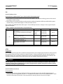
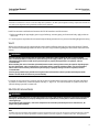
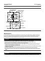
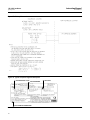
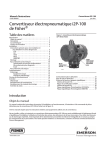
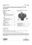
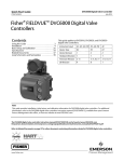
Instruction Manual i2P-100 Transducer D103198X012 January 2013 Fisherr i2P-100 Electro‐Pneumatic Transducer Contents Introduction . . . . . . . . . . . . . . . . . . . . . . . . . . . . . . . . . 1 Scope of Manual . . . . . . . . . . . . . . . . . . . . . . . . . . . . . 1 Description . . . . . . . . . . . . . . . . . . . . . . . . . . . . . . . . . 4 Specifications . . . . . . . . . . . . . . . . . . . . . . . . . . . . . . . 4 Educational Services . . . . . . . . . . . . . . . . . . . . . . . . . 4 Installation . . . . . . . . . . . . . . . . . . . . . . . . . . . . . . . . . . 5 Hazardous Area Classifications and Special Instructions for “Safe Use” and Installation in Hazardous Locations . . . . . . . . . . . . . . . . . . . . . 6 CSA . . . . . . . . . . . . . . . . . . . . . . . . . . . . . . . . . . . . 6 FM . . . . . . . . . . . . . . . . . . . . . . . . . . . . . . . . . . . . . 7 ATEX . . . . . . . . . . . . . . . . . . . . . . . . . . . . . . . . . . . 7 IECEx . . . . . . . . . . . . . . . . . . . . . . . . . . . . . . . . . . . 9 Mounting . . . . . . . . . . . . . . . . . . . . . . . . . . . . . . . . . 10 Pneumatic Connections . . . . . . . . . . . . . . . . . . . . . 10 Supply Pressure Requirements . . . . . . . . . . . . 11 Diagnostic Connections . . . . . . . . . . . . . . . . . . 12 Vent . . . . . . . . . . . . . . . . . . . . . . . . . . . . . . . . . . 13 Electrical Connections . . . . . . . . . . . . . . . . . . . . . . . 13 Operating Information . . . . . . . . . . . . . . . . . . . . . . . . 14 Calibration . . . . . . . . . . . . . . . . . . . . . . . . . . . . . . . . 14 Equipment Required . . . . . . . . . . . . . . . . . . . . . 15 Calibration Procedure . . . . . . . . . . . . . . . . . . . . 15 Principle of Operation . . . . . . . . . . . . . . . . . . . . . . . . 16 Maintenance . . . . . . . . . . . . . . . . . . . . . . . . . . . . . . . . 17 Troubleshooting . . . . . . . . . . . . . . . . . . . . . . . . . . . . 18 Converter Module Replacement . . . . . . . . . . . . . . 19 Electronics Module Replacement . . . . . . . . . . . . . . 19 Relay Maintenance . . . . . . . . . . . . . . . . . . . . . . . . . . 20 Figure 1. Fisher i2P‐100 Electro‐Pneumatic Transducer REPLACEABLE FILTER WITH REMOVABLE ORIFICE INTEGRAL PNEUMATIC RELAY VENT W8710 Parts Ordering . . . . . . . . . . . . . . . . . . . . . . . . . . . . . . . Parts List . . . . . . . . . . . . . . . . . . . . . . . . . . . . . . . . . . . Loop Schematics/Nameplates . . . . . . . . . . . . . . . . . CSA Loop Schematic . . . . . . . . . . . . . . . . . . . . . . . . CSA/FM Approvals Nameplate . . . . . . . . . . . . . . . . FM Loop Schematic . . . . . . . . . . . . . . . . . . . . . . . . . ATEX/IECEx Approvals Nameplate . . . . . . . . . . . . . 21 22 25 25 25 26 26 Introduction Scope of Manual This instruction manual provides installation, operation, maintenance, and parts ordering information for the Fisher i2P‐100 transducer (see figure 1). Refer to separate manuals for instructions covering equipment used with the transducer. Do not install, operate, or maintain an i2P-100 electro‐pneumatic transducer without being fully trained and qualified in valve, actuator, and accessory installation, operation and maintenance. To avoid personal injury or property damage it is important to carefully read, understand, and follow all of the contents of this manual, including all safety cautions and warnings. If you have any questions about these instructions, contact your Emerson Process Management sales office. www.Fisher.com Instruction Manual i2P-100 Transducer D103198X012 January 2013 Table 1. Specifications Frequency Response: Gain is attenuated 3 dB at 6 Hz with transducer output signal piped to a typical instrument input Input Signal Available as standard with 4‐20 mA. User configurable by dip switch for split ranging, see table below. Temperature Effect: ±0.14% per degrees Celsius (±0.075% per degrees Fahrenheit) of span Output Signal(1) Supply Pressure Effect: 0.2% of full scale output span per psi supply pressure change Available as standard 0.2 to 1.0 bar (3 to 15 psig), 0.4 to 2.0 bar (6 to 30 psig), or 0.14 to 2.3 bar (2 to 33 psig). User configurable by dip switch selection and zero and span potentiometer adjustment, see table below. Input Signal Electromagnetic Compatibility Meets EN 61326‐1 (First Edition) Immunity—Industrial locations per Table 2 of EN 61326‐1 Standard. Performance is shown in table 2 below. Emissions—Class A ISM equipment rating: Group 1, Class A Output Pressure Bar psig 0.2 to 1.0 3 to 15 0.4 to 2.0 6 to 30 0.14 to 2.3 2 to 33 4‐12 mA DC 0.2 to 1.0 3 to 15 12‐20 mA DC 0.2 to 1.0 3 to 15 4‐20 mA DC Vibration Effect: Less than 1% of full scale output span when tested to ISA S75.13 Operating Ambient Temperature Limits(2) -40 to 85_C (-40 to 185_F) Equivalent Circuit Electrical Seal The i2P‐100 equivalent circuit is a series circuit consisting of a constant voltage drop (battery) of approximately 4 VDC and a total resistance of 40 ohms. Input is shunted by two 6.8 V zener diodes (see figure 9). Single sealed device per ANSI/ISA 12.27.01 Electrical Classification Hazardous Area: Supply Pressure(2) CSA—Intrinsically Safe, Explosion-proof, Type n, Dust‐Ignition proof Recommended: 0.3 bar (5 psi) higher than upper range limit of output signal Maximum: 3.4 bar (50 psig) FM—Intrinsically Safe, Explosion-proof, Type n, Non‐incendive, Dust‐Ignition proof ATEX—Intrinsically Safe & Dust, Flameproof & Dust, Type n & Dust Medium: Air or Natural Gas(3) IECEx—Intrinsically Safe, Flameproof, Type n Average Steady-State Air Consumption Refer to Hazardous Area Classifications and Special Instructions for “Safe Use” and Installation in Hazardous Locations, starting on page 6, for specific approval information 0.12 m3/hr (4.22 scfh) at 1.4 bar (20 psig) supply pressure Maximum Output Air Capacity(4) Approved for use with natural gas(3) 8.0 m3/hr (300 scfh) at 1.4 bar (20 psig) supply pressure Other Classifications/Certifications GOST‐R—Russian GOST‐R INMETRO—Brazil KGS—Korea Gas Safety Corporation NEPSI—China RTN—Russian Rostekhnadzor Performance(5) Reference Accuracy: ±1.0% of full scale output span; includes combined effects of hysteresis, linearity, and deadband Independent Linearity: ±0.75% of full scale output span Contact your Emerson Process Management sales office for classification/certification specific information Hysteresis: 0.4% of full scale output span (continued) 2 Instruction Manual i2P-100 Transducer D103198X012 January 2013 Table 1. Specifications (continued) Electrical Housing: Mounting Position When Remotely Vented CSA—Type 4X Encl. FM—NEMA 4X ATEX—IP66 IECEx—IP66 No Remote Venting CSA—Type 3 Encl. FM—NEMA 3 ATEX—IP64 IECEx—IP64 Connections J Actuator J pipestand or J surface Approximate Weight (Transducer Only) 2.5 kg (5.5 lbs) Actuator Stroking Time Supply and Output Pressure: 1/4 NPT internal connection Vent: 1/4 NPT internal Electrical: Standard 1/2 NPT Wire Size: 18 to 22 AWG See figure 2 Declaration of SEP Adjustments(1) Zero and Span: Trim potentiometers (20 turn) for zero and span adjustments are located under the housing cap (see figure 10). Switch: Allows input signal split range and user‐configurable 0.14 to 2.3 bar (2 to 33 psig) output. Fisher Controls International LLC declares this product to be in compliance with Article 3 paragraph 3 of the Pressure Equipment Directive (PED) 97 / 23 / EC. It was designed and manufactured in accordance with Sound Engineering Practice (SEP) and cannot bear the CE marking related to PED compliance. However, the product may bear the CE marking to indicate compliance with other applicable European Community Directives. NOTE: Specialized instrument terms are defined in ANSI/ISA Standard 51.1 - Process Instrument Terminology 1. For other ranges, zero and span adjustments are needed. 2. The pressure and temperature limits in this document and any applicable standard or code limitation should not be exceeded. 3. This product is approved for use with natural gas. 4. Normal m3/hr—Normal cubic meters per hour (0_C and 1.01325 bar, absolute). Scfh—Standard cubic feet per hour (60_F and 14.7 psia). 5. Performance values are obtained using a transducer with a 4 to 20 mA DC input signal and a 0.2 to 1.0 bar (3 to 15 psig) output signal at an ambient temperature of 24_C (75_F). Table 2. EMC Summary Results—Immunity Port Phenomenon Basic Standard Performance Criteria(1) Electrostatic discharge (ESD) IEC 61000‐4‐2 4kV Contact 8kV Air A Radiated EM field IEC 61000‐4‐3 80 to 1000 MHz @ 10V/m with 1 kHz AM at 80% 1400 to 2000 MHz @ 3V/m with 1 kHz AM at 80% 2000 to 2700 MHz @ 1V/m with 1 kHz AM at 80% A Burst (fast transients) IEC 61000‐4‐4 1 kV A Surge IEC 61000‐4‐5 1 kV (line to ground only, each) A Conducted RF IEC 61000‐4‐6 150 kHz to 80 MHz at 3 Vrms A Enclosure I/O signal/control Test Level Specification limit = ±1% of span 1. A=No degradation during testing. B = Temporary degradation during testing, but is self‐recovering. CAUTION Dropping or rough handling of the transducer can cause damage to the converter module resulting in a shifted output or a minimum output. 3 Instruction Manual i2P-100 Transducer D103198X012 January 2013 Figure 2. Output‐Time Relationships for Fisher i2P‐100 Transducer 100 OUTPUT (% OF i2P‐100 OUTPUT SPAN) 90 80 70 LOADING 60 50 40 EXHAUSTING 30 20 10 0 0 10 20 A6815 30 40 50 60 70 80 90 100 TIME (%) Description The transducer receives a 4‐20 mA DC input signal and transmits a proportional user field‐configurable pneumatic output pressure to a final control element. The pneumatic output range are typically 0.2 to 1.0 bar (3 to 15 psig), 0.4 to 2.0 bar (6 to 30 psig), and 0.14 to 2.3 bar (2 to 33 psi). A typical application is in electronic control loops where the final control element is a control valve assembly that is pneumatically operated. The input signal and output pressure range of the transducer is indicated on the nameplate, attached to the housing. Specifications Specifications for the i2P‐100 transducer are listed in table 1. WARNING This product is intended for a specific current range, temperature range and other application specifications. Applying different current, temperature and other service conditions could result in malfunction of the product, property damage or personal injury. Educational Services For information on available courses for the i2P‐100 electro‐pneumatic transducer, as well as a variety of other products, contact: Emerson Process Management Educational Services, Registration P.O. Box 190; 301 S. 1st Ave. Marshalltown, IA 50158-2823 Phone: 800-338-8158 or Phone: 641-754-3771 FAX: 641-754-3431 e‐mail: [email protected] 4 Instruction Manual i2P-100 Transducer D103198X012 January 2013 Installation The i2P‐100 transducer has been designed and approved for use with either air or natural gas as the supply medium. If using natural gas as the pneumatic supply medium, natural gas will be used in the pneumatic output connections of the transducer to any connected equipment. In normal operation the unit will vent the supply medium into the surrounding atmosphere unless it is remotely vented. When using natural gas as the supply medium, in a non‐hazardous location in a confined area, remote venting of the unit is required. Failure to do so could result in personal injury, property damage, and area re‐classification. For hazardous locations remote venting of the unit may be required, depending upon the area classification, and as specified by the requirements of local, regional, and federal codes, rules and regulations. Failure to do so when necessary could result in personal injury, property damage, and area re‐classification. Additional information for installation and safe use in hazardous locations can be found in Hazardous Area Classifications and Special Instructions for “Safe Use” and Installation in Hazardous Locations. WARNING To avoid personal injury or property damage from the sudden release of pressure, air, or natural gas: D Always wear protective clothing, gloves, and eyewear when performing any installation operations. D If installing into an existing application, also refer to the WARNING at the beginning of the Maintenance section of this instruction manual. D Check with your process or safety engineer for any additional measures that must be taken to protect against process media. WARNING This unit vents the supply medium into the surrounding atmosphere. When installing this unit in a non‐hazardous (non‐classified) location in a confined area, with natural gas as the supply medium, you must remotely vent this unit to a safe location. Failure to do so could result in personal injury or property damage from fire or explosion, and area re‐classification. When installing this unit in a hazardous (classified) location remote venting of the unit may be required, depending upon the area classification, and as specified by the requirements of local, regional, and federal codes, rules and regulations. Failure to do so when necessary could result in personal injury or property damage from fire or explosion, and area re‐classification. Vent line piping should comply with local and regional codes and should be as short as possible with adequate inside diameter and few bends to reduce case pressure buildup. When received from the factory, the set screws (key 8), which provide a locking feature for the housing caps (key 2), are backed off approximately 1 turn. When using the i2P‐100 transducer in explosive atmospheres these set screws must be fully engaged. WARNING When using this unit in explosive atmospheres, the set screws (key 8) must be fully engaged to lock/secure the housing caps. Failure to fully engage these set screws could result in unauthorized opening of the unit, which may result in personal injury or property damage caused by fire or explosion. 5 Instruction Manual i2P-100 Transducer D103198X012 January 2013 Hazardous Area Classifications and Special Instructions for “Safe Use” and Installation in Hazardous Locations Certain nameplates may carry more than one approval, and each approval may have unique installation/wiring requirements and/or conditions of “safe use”. These special instructions for “safe use” are in addition to, and may override, the standard installation procedures. Special instructions are listed by approval. Note This information supplements the nameplate markings affixed to the product. Always refer to the nameplate itself to identify the appropriate certification. WARNING Failure to follow these conditions of “safe use” could result in personal injury or property damage from fire or explosion, and area re‐classification. CSA Intrinsically Safe, Explosion-proof, Type n, Dust‐Ignition proof No special conditions of safe use. Refer to table 3 for approval information, figure 15 for the CSA loop schematic and figure 16 for a typical CSA/FM approval nameplate. Table 3. Hazardous Area Classifications—CSA (Canada) Certification Body CSA *When remotely vented. 6 Certification Obtained Intrinsically Safe Ex ia IIC T3/T4/T5 per drawing GE07471 Ex ia Intrinsically Safe Class I, II, III Division 1 GP A,B,C,D,E,F,G per drawing GE07471 Explosion-proof Ex d IIC T5/T6 Class I, Division 1 GP, A,B,C,D T5 Type n Ex nC IIC T5/T6 Class I, Division 2, GP A,B,C,D T5 Class II, Division 1, GP E,F,G T5 Class II, Division 2 GP F,G T5 Class III Entity Rating Vmax ≤ 30 VDC Imax ≤ 150 mA Pi ≤ 1.0 W Ci = 0 nF Li = 0 mH Temperature Code Enclosure Rating T3 (Tamb ≤ 85°C) T4 (Tamb ≤ 81°C) T5 (Tamb ≤ 46°C) CSA Type 4X Encl.* --- T5 (Tamb ≤ 85°C) T6 (Tamb ≤ 75°C) CSA Type 4X Encl.* --- T5 (Tamb ≤ 85°C) T6 (Tamb ≤ 75°C) CSA Type 4X Encl.* --- T5 (Tamb ≤ 85°C) CSA Type 4X Encl.* Instruction Manual i2P-100 Transducer D103198X012 January 2013 FM Special Conditions of Use Intrinsically Safe, Explosion-proof, Type n, Non‐incendive, Dust‐Ignition proof 1. When product is used with natural gas as the pneumatic medium, the maximum working pressure of the natural gas supply is limited to 50 psi. 2. When product is used with natural gas as the pneumatic medium the product shall be provided with the proper remote venting, as described on page 13 of this instruction manual. Refer to table 4 for additional information, figure 17 for the FM loop schematic, and figure 16 for a typical CSA/FM approval nameplate. Table 4. Hazardous Area Classifications—FM (United States) Certification Body Certification Obtained Intrinsically Safe Class I Zone 0 AEx ia IIC T3/T4/T5 per drawing GE07470 Class I, II, III Division 1 GP A, B,C,D,E,F,G per drawing GE07470 FM Explosion-proof Class I Zone 1 AEx d IIC T5/T6 Class I, Division 1, GP A,B,C,D T5/T6 Type n Class I Zone 2 AEx nC IIC T5/T6 Class I, Division 2, GP A, B,C,D T5/T6 Class II, Division 1, GP E,F,G T5/T6 Class II, Division 2, GP F,G T5/T6 Class III Entity Rating Vmax ≤ 30 VDC Imax ≤ 150 mA Pi ≤ 1.0 W Ci = 0 nF Li = 0 mH Temperature Code Enclosure Rating T3 (Tamb ≤ 85°C) T4 (Tamb ≤ 81°C) T5 (Tamb ≤ 46°C) NEMA 4X* --- T5 (Tamb ≤ 85°C) T6 (Tamb ≤ 75°C) NEMA 4X* --- T5 (Tamb ≤ 85°C) T6 (Tamb ≤ 75°C) NEMA 4X* --- T5 (Tamb ≤ 85°C) T6 (Tamb ≤ 75°C) NEMA 4X* *When remotely vented ATEX All Approvals All ATEX approved units come with a combined nameplate which carries multiple approvals (intrinsic safety and dust, flameproof and dust, and Type n and dust), as shown in figure 18. During installation, only one type of protection method is allowed. The unit shall be marked by the end-user as to which protection method it was installed as and shall not be changed or utilized in any other manner than was originally marked by the end‐user. WARNING For ATEX approvals only, end‐user must select and mark only one protection method upon installation. Once marked it shall not be changed. Failure to follow these instructions will jeopardize the explosion safety of the transducer, and may result in personal injury or property damage. Special Conditions for Safe Use Intrinsically Safe 1. Before putting in service, the user shall permanently cross out the areas on the nameplate with the types of protection that are not applicable (Ex ia IIC T3... T5, KEMA 05ATEX1109 X or Ex nA II T5/T6, KEMA 05ATEX1119) or mark the selected type of protection. Once determined the type of protection may not be changed. 7 Instruction Manual i2P-100 Transducer D103198X012 January 2013 2. Because the enclosure of the i2P‐100 transducer is made of aluminum, if it is mounted in an area where the use of category 1 G apparatus is required, it must be installed such, that, even in the event of rare incidents, ignition sources due to impact and friction sparks are excluded. 3. Ambient temperature range: -40_C - + 46_C for temperature class T5 -40_C - + 81_C for temperature class T4 -40_C - + 85_C for temperature class T3 Electrical data: Unit must be installed with appropriate I.S barrier with maximum entity ratings as follows: Ui = 30 V ; Ii = 150 mA (resistively limited) ; Pi = 1 W ; Ci = 0 nF ; Li = 0 mH Flameproof 1. Before putting in service, the user shall permanently cross out the areas on the nameplate with the types of protection that are not applicable (Ex ia IIC T3... T5, KEMA 05ATEX1109 X or Ex nA II T5/T6, KEMA 05ATEX1119) or mark the selected type of protection. Once determined the type of protection may not be changed. 2. Electrical connections are typically made using either cable or conduit. D If using a cable connection, the cable entry and closing devices shall be certified in type of protection flameproof enclosure “d”, suitable for the conditions of use and correctly installed. For ambient temperatures over 70_C, suitable heat resistant cables and cable glands shall be used. D If using a rigid conduit connection, a certified sealing device in type of protection flameproof enclosure “d”, such as a conduit seal with setting compound shall be provided immediately to the entrance of the valve housing. For ambient temperature over 70_C, suitable heat resistant wiring and setting compound for the conduit seal shall be used. Type n 1. Before putting in service, the user shall permanently cross out the areas on the nameplate with the types of protection that are not applicable (Ex ia IIC T3... T5, KEMA 05ATEX1109 X or Ex nA II T5/T6, KEMA 05ATEX1119) or mark the selected type of protection. Once determined the type of protection may not be changed. Refer to table 5 for additional information and figure 18 for a typical ATEX/IECEx approval nameplate. Table 5. Hazardous Area Classifications—ATEX Certificate Certification Obtained Intrinsically Safe II 1 GD Gas Ex ia IIC T3/T4/T5 Dust T95°C (Tamb ≤ 85°C) ATEX Ui ≤ 30 VDC Ii ≤ 150 mA Pi ≤ 1.0 W Ci = 0 nF Li = 0 mH Temperature Code Enclosure Rating T3 (Tamb ≤ 85°C) T4 (Tamb ≤ 81°C) T5 (Tamb ≤ 46°C) IP66* Flameproof II 2 GD Gas Ex d IIC T5/T6 Dust T95°C (Tamb ≤ 85°C) --- T5 (Tamb ≤ 85°C) T6 (Tamb ≤ 75°C) IP66* Type n II 3 GD Gas Ex nC II T5/T6 Dust T95°C (Tamb ≤ 85°C) --- T5 (Tamb ≤ 85°C) T6 (Tamb ≤ 75°C) IP66* *When remotely vented. 8 Entity Rating Instruction Manual i2P-100 Transducer D103198X012 January 2013 IECEx Standards used for IECEx Certification IEC60079‐0:2004, IEC60079‐1:2001, IEC60079‐11:2006, and IEC60079‐15:2005 Conditions of Certification Intrinsically Safe, Type n, Flameproof The Intrinsically Safe version has the following Entity Parameters: Ui = 30 V ; Ii = 150 mA ; Pi = 1.0 W ; Ci = 0 uF ; Li = 0 uH Refer to table 6 for additional information and figure 18 for a typical ATEX/IECEx approval nameplate. Table 6. Hazardous Area Classifications—IECEx Certificate Certification Obtained Intrinsically Safe Gas Ex ia IIC T3/T4/T5 IECEx Flameproof Gas Ex d IIC T5/T6 Type n Gas Ex nC IIC T5/T6 Entity Rating Ui ≤ 30 VDC Ii ≤ 150 mA Pi ≤ 1.0 W Ci = 0 uF Li = 0 uH Temperature Code Enclosure Rating T3 (Tamb ≤ 85°C) T4 (Tamb ≤ 81°C) T5 (Tamb ≤ 46°C) IP66* --- T5 (Tamb ≤ 85°C) T6 (Tamb ≤ 75°C) IP66* --- T5 (Tamb ≤ 85°C) T6 (Tamb ≤ 75°C) IP66* *When remotely vented. 9 Instruction Manual i2P-100 Transducer D103198X012 January 2013 Mounting When a transducer is ordered as part of a control valve assembly, the factory mounts the transducer on the actuator and connects the necessary tubing, then adjusts the transducer as specified on the order. See figures 3 and 4 for typical mounting configurations. Figure 3. Fisher i2P‐100 Electro‐Pneumatic Transducer Mounted on a Size 30 667 Sliding‐Stem Actuator Figure 4. Fisher i2P‐100 Electro‐Pneumatic Transducer Mounted on a Size 33 1052 Rotary Actuator with 3610J Positioner and V300B Rotary Valve CONDUIT CONNECTION CONDUIT CONNECTION FIELD TERMINATION AND ELECTRONICS MODULE CAP CONVERTER MODULE CAP CONVERTER MODULE CAP FIELD TERMINATION AND ELECTRONICS MODULE CAP W8693 W8723 Transducers also can be ordered separately for mounting on a control valve assembly already in service, or for mounting on a 2 inch diameter pipestand, or a flat surface. The transducer may be ordered either with or without mounting parts. CAUTION Do not mount the vent in a downward position as the vent will not drain properly and may become blocked with ice or debris, resulting in process instability. Mounting parts include a mounting plate and bolts and, if ordered for pipestand mounting, a pipe clamp. Tubing is not included if the transducer is not factory mounted. Use 3/8‐inch diameter tubing for all input and output connections. The length of tubing between the transducer output and the final control element should be as short as possible. Transducer overall dimensions are shown in figure 5. If weatherproofing is required, mount the transducer so that the vent can drain. Do not allow moisture or condensate to collect in the vent. Pneumatic Connections As shown in figure 5, all pressure connections on the transducer are 1/4 NPT internal connections. Use 3/8‐inch tubing for all pressure connections. Refer to the vent subsection below for remote vent connections. 10 Instruction Manual i2P-100 Transducer D103198X012 January 2013 Figure 5. Dimensions and Connections 34.7 (1.37) 103.9 (4.09) 103.9 (4.09) 36.3 (1.43) 74.2 (2.92) 98.7 (3.89) 81.6 (3.21) 22.3 (0.88) 1/2 14 NPT CONDUIT CONNECTION 58.7 (2.31) 1/4 18 NPT VENT OR PIPE‐A‐WAY CONNECTION 67.8 (2.67) 33.3 (1.31) 1/4 18 NPT SUPPLY CONNECTION 1/4 18 NPT OUTPUT CONNECTION 55.7 (2.19) GE0643 (sheet 1 of 4) 67 (2.62) CAP REMOVAL CLEARANCE 22.9 (0.90) 33.3 (1.31) 75.2 (2.96) 1/4 18 NPT OUTPUT CONNECTION 33.3 (1.31) 75.7 (2.98) 67 (2.62) CAP REMOVAL CLEARANCE mm (INCH) Supply Pressure Requirements WARNING Severe personal injury or property damage could result from an unstable process if the instrument supply medium is not clean, dry, oil‐free and noncorrosive. While use and regular maintenance of a filter that removes particles larger than 40 micrometers in diameter will suffice in most applications, check with an Emerson Process Management field office and industry instrument air quality standards for use with corrosive air or if you are unsure about the proper amount or method of air filtration or filter maintenance. Supply pressure must be clean, dry air or noncorrosive gas. Use a Fisher 67CFR filter regulator with standard 5 micrometer filter, or equivalent, to filter and regulate supply air. The filter regulator can be mounted on a bracket with the transducer as shown in figure 6 or mounted on the actuator mounting boss. An output pressure gauge may be installed on the regulator to indicate the supply pressure to the transducer. Also, as an aid for calibration, a second gauge may be installed on the transducer to indicate transducer output pressure. Connect the nearest suitable supply source to the 1/4 NPT IN connection on the filter regulator (if furnished) or to the 1/4 NPT SUPPLY connection on the transducer case (if the filter regulator is not attached). 11 Instruction Manual i2P-100 Transducer D103198X012 January 2013 Figure 6. Typical Fisher i2P‐100 Mounting With 67CFR Filter Regulator i2P‐100 TRANSDUCER MOUNTING BRACKET REGULATOR CHAMFER 45_ to 27/64 DIA 1/4‐18 NPT EXTERNAL PIPE NIPPLE 2.5 INCH Diagnostic Connections To support diagnostic testing of valve/actuator/positioner packages, special connectors and hardware are available. Typical connector installations are shown in figure 7. The hardware used includes a 1/4 NPT pipe nipple and pipe tee with a 1/8 NPT pipe bushing for the connector. The connector consists of a 1/8 NPT body and body protector. Figure 7. Diagnostics Hookup for Fisher i2P‐100 Transducer STEM PROVIDED WHEN GAUGE IS SPECIFIED BODY PROTECTOR BODY PIPE BUSHING GE06439‐A (sheet 1 of 4) B2395‐1 12 PIPE TEE PIPE NIPPLE (SEE FIGURE 6) GAUGE Instruction Manual D103198X012 i2P-100 Transducer January 2013 Note If the i2P‐100 transducer is used in a valve assembly with a positioner, no hook‐up for diagnostic testing is required for the i2P‐100. The hook‐up for diagnostic testing should be installed at the positioner. Install the connectors and hardware between the i2P‐100 transducer and the actuator. 1. Before assembling the pipe nipple, pipe tee, pipe bushings, actuator piping, and connector body, apply sealant to all threads. 2. Turn the pipe tee to position the connector body and body protector for easy access when doing diagnostic testing. Vent When using natural gas as the supply medium ensure that the following warnings are read and understood. Contact your Emerson Process Management sales office if you have any questions regarding the information contained in this section. WARNING This unit vents the supply medium into the surrounding atmosphere. When installing this unit in a non‐hazardous (non‐classified) location in a confined area, with natural gas as the supply medium, you must remotely vent this unit to a safe location. Failure to do so could result in personal injury or property damage from fire or explosion, and area re‐classification. When installing this unit in a hazardous (classified) location remote venting of the unit may be required, depending upon the area classification, and as specified by the requirements of local, regional, and federal codes, rules and regulations. Failure to do so when necessary could result in personal injury or property damage from fire or explosion, and area re‐classification. Vent line piping should comply with local and regional codes and should be as short as possible with adequate inside diameter and few bends to reduce case pressure buildup. If a remote vent is required, the vent line must be as short as possible with a minimum number of bends and elbows. To connect a remote vent, remove the plastic vent (key 71, figure 13). The vent connection is 1/4 NPT internal. Use 3/8‐inch tubing to provide a remote vent. Electrical Connections WARNING For explosion‐proof applications, or when using natural gas as the supply medium, disconnect power before removing the housing cap. Personal injury or property damage from fire or explosion may result if power is not disconnected before removing the cap. For intrinsically safe installations, refer to the nameplate or to instructions provided by the barrier manufacturer, for proper wiring and installation. Note For North American explosion‐proof applications in the Class/Division system, the i2P‐100 has been designed such that a conduit seal is not required. For all other applications install the product as per local, regional, or national code, rules, and regulations. 13 Instruction Manual i2P-100 Transducer D103198X012 January 2013 WARNING Select wiring and/or cable glands that are rated for the environment of use (such as hazardous location, ingress protection, and temperature). Failure to use properly rated wiring and/or cable glands can result in personal injury or property damage from fire or explosion. Wiring connections must be in accordance with local, regional, and national codes for any given hazardous area approval. Failure to follow the local, regional, and national codes could result in personal injury or property damage from fire or explosion. Use the 1/2 NPT conduit connection, shown in figure 5, for installation of field wiring. Refer to figures 8, 9, and 10 when connecting field wiring from the control device to the transducer. Connect the positive wire from the control device to the transducer “+” terminal and, the negative wire from the control device to the transducer “-” terminal. Do not overtighten the terminal screws. Maximum torque is 0.45 NSm (4 lbfSin.). Connect the transducer grounding terminal to earth ground. Grounding terminals are provided both inside and outside the transducer housing. Figure 8. Typical Field Wiring Diagram TERMINAL BLOCK CONTROL DEVICE + − TRANSDUCER HOUSING FIELD WIRING − Figure 9. Equivalent Circuit + 4 - 20 mA + − 1 6.8V 6.8V 4V 40 Ohm EARTH GROUND NOTE: 1 FOR TROUBLESHOOTING OR MONITORING OPERATION, AN INDICATING DEVICE CAN BE A VOLTMETER ACROSS A 250 OHM RESISTOR OR A CURRENT METER. A3875 Operating Information During normal operation, the output of the i2P‐100 transducer is connected to the final control element. Calibration WARNING On explosion‐proof instruments, or when using natural gas as the supply medium, remove electrical power before removing either of the the housing caps in a hazardous area. Personal injury or property damage may result from fire or explosion if power is applied to the transducer with the cap removed in a hazardous area. 14 Instruction Manual i2P-100 Transducer D103198X012 January 2013 For intrinsically safe areas, current monitoring during operation must be with a meter approved for use in hazardous areas. Equipment Required Choose a current or voltage source that is capable, without switching ranges, of driving the transducer through its entire input range. Switching ranges on a current or voltage source will produce spikes or mid‐scale reverses in the input signal presented to the transducer, causing errors. The current source should be capable of delivering 30 mA with 30 VDC maximum compliance voltage. Calibration Procedure WARNING To avoid personal injury or property damage due to an uncontrolled process provide some temporary means of process control before beginning the calibration procedure. Refer to figure 10 for adjustment locations. Figure 10. Zero and Span Adjustments and Switch Settings ZERO ADJUSTMENT PCB/CUP ASSEMBLY SETTING B(1,2) SETTING A OR 4‐20 mA3‐15 psi SETTING C(1) OR 4‐12 mA3‐15 psi 12‐20 mA3‐15 psi OR 4‐20 mA6‐30 psi OR SPAN ADJUSTMENT NOTES: - + { FIELD WIRING CONNECTION 4‐20 mA2‐33 psi SWITCH SETTINGS(3) THE SWITCH SETTINGS WILL PRODUCE THE PERFORMANCE CHARACTERISTICS AS INDICATED. FOR EXAMPLE, BOTH SWITCHES PLACED IN THE OFF POSITION WILL CREATE A 4‐20 mA INPUT WITH A 3‐15 PSIG OUTPUT PERFORMANCE CHARACTERISTIC 1. INPUT SIGNAL SPLIT RANGE IS SELECTABLE VIA DIP‐SWITCH CONFIGURATION. 2. OUTPUT RANGE DIP‐SWITCH SELECTION FOR 0.14 TO 2.0 BAR (2 TO 33 PSIG) USES SETTING B AND REQUIRES ZERO TO SPAN ADJUSTMENTS. FOR OTHER RANGES, ZERO AND SPAN ADJUST MENTS NEEDED. 3. SWITCH 1 SET TO THE ON POSITION AND SWITCH 2 SET TO THE OFF POSITION IS NOT A VALID SWITCH SETTING. GE03345 Note The following steps are for a 4‐20 mA, 0.2 to 1.0 bar (3 to 15 psig) configured unit. The same procedure is used for other configurations. 15 i2P-100 Transducer January 2013 Instruction Manual D103198X012 1. Remove electronics module cover (cover adjacent to conduit entry, see figure 3 and 4). CAUTION Do not attempt to remove either of the housing caps if the locking set screws (key 8) are engaged. Removing housing caps without disengaging the set screws can cause damage to the housing caps. 2. Input and output ranges are selectable by dip switch selection. Refer to figure 10 for dip switch settings. Adjust dip switch settings and zero and span as necessary to achieve the desired input/output range. 3. If a current source other than the control device is used as the input source, disconnect the control device and connect the current source positive terminal to the transducer “+” terminal and the current source negative terminal to the transducer “-” terminal. If an external meter is used, connect the current source positive terminal to the transducer “+” terminal. Connect the meter positive terminal to the transducer “-” terminal and the meter negative terminal to the current source negative terminal as shown in figure 8. 4. Check the supply pressure to ensure it is at the recommended pressure. Refer to table 1, the Specifications table, for supply pressure recommendations. 5. Adjust the input current to the low mA DC. 6. The output pressure should be 0.2 bar (3 psig). If not, adjust the ZERO potentiometer until the output pressure is 0.2 bar (3 psig). 7. Adjust the input current to the high mA DC. 8. The output pressure should be 1.0 bar (15 psig). If not, adjust the SPAN potentiometer until the output pressure is 1.0 bar (15 psig). 9. Repeat steps 5 through 8 until the output pressure is within the referenced accuracy requirements without further adjustment. 10. If a current source other than the control device was used, disconnect the current source and reconnect the control device. Principle of Operation The converter module receives a standard DC current input signal from a control device to operate coils in a force balanced beam system which in turn, controls bleed air through an integral nozzle/flapper arrangement. The nozzle pressure provides the input signal to operate the relay as shown in figure 11. Relay output pressure is applied, through tubing, directly to the final control element or valve/actuator assembly. 16 Instruction Manual i2P-100 Transducer D103198X012 January 2013 Figure 11. Fisher i2P‐100 Transducer Schematic FIELD TERMINATOR AND ELECTRONICS CIRCUIT COIL CURRENT‐TO‐PRESSURE CONVERTER ASSEMBLY MAGNET ZERO AND SPAN CIRCUIT F BEAM { - DC CURRENT INPUT SIGNAL DIAPHRAGM FLAPPER + F NOZZLE PNEUMATIC RELAY EXHAUST RESTRICTION DIAPHRAGM OUTPUT PRESSURE VALVE PLUG SUPPLY PRESSURE A3877-2 Maintenance Due to normal wear or damage from external sources such as debris in the supply medium, periodic maintenance or repair of the transducer may be necessary. Maintenance of the transducer consists of troubleshooting, removal for inspection, and replacement of component parts, as well as removal and inspection of the external removable filter/restriction and cleaning or replacing as necessary (see figure 1). WARNING To avoid personal injury or property damage from the sudden release of pressure, air or natural gas: D Always wear protective clothing, gloves, and eyewear when performing any maintenance operations. D Do not remove the actuator from the valve while the valve is still pressurized. D Disconnect any operating lines providing air pressure, electric power, or a control signal to the actuator. Be sure the actuator cannot suddenly open or close the valve. D Use bypass valves or completely shut off the process to isolate the valve from process pressure. Relieve process pressure on both sides of the valve. D Use lock‐out procedures to be sure that the above measures stay in effect while you work on the equipment. D Check with your process or safety engineer for any additional measures that must be taken to protect against process media. WARNING When using natural gas as the supply medium, or for explosion proof applications, the following warnings also apply: 17 i2P-100 Transducer January 2013 Instruction Manual D103198X012 D Remove electrical power before removing either housing cap. Personal injury or property damage from fire or explosion may result if power is not disconnected before removing either cap. D Remove electrical power before disconnecting any of the pneumatic connections or removing the external removeable filter/restriction. When disconnecting any of the pneumatic connections or the external removeable filter/restriction, natural gas will seep from the unit and any connected equipment into the surrounding atmosphere. Personal injury or property damage may result from fire or explosion if preventative measures are not taken, such as adequate ventilation and the removal of any ignition sources. CAUTION Do not attempt to remove either of the housing caps if the locking set screws (key 8) are engaged. Removing housing caps without disengaging the set screws can cause damage to the housing caps. CAUTION When replacing components, use only components specified by the factory. Always use proper component replacement techniques, as presented in this manual. Improper techniques or component selection may invalidate the approvals and the product specifications, as indicated in table 1. It may also impair operations and the intended function of the device. The converter module and the electronics module are non‐repairable. If troubleshooting or alignment attempts indicate a faulty converter or electronics module, replace the module or return the transducer to your Emerson Process Management sales office for repair. Troubleshooting The following procedures require taking the control valve/actuator assembly out of service. Provide some temporary means of process control before taking the control valve out of service. Electrical 1. Ensure terminal lug connections from the control device to the transducer are of the correct polarity (refer to the electrical connection procedures in the Installation section of this manual). 2. At the transducer, ensure that the mA DC signal is applied, and ensure that it is within the 4 to 20 mA range. 3. Check switches and ensure that they are properly set. Refer to figure 10. 4. If the problem has not been resolved, see Electronics Module Replacement in this manual. Pneumatic Provide a 4‐30 mA DC current source, supply pressure, and a gauge to monitor the output pressure when checking transducer operation. Refer to figure 13 for key number locations. 1. Ensure that supply pressure to the transducer meets your requirements [0.3 bar (5 psi) higher than upper range limit of output signal, with a maximum of 3.4 bar (50 psi)]. 2. Ensure that the filter (key 11) and restrictor (key 10) are open and clean. Remove the two screws (key 14), the filter cap (key 13) and the O‐ring (key 12) to access the filter and restrictor. 18 Instruction Manual D103198X012 i2P-100 Transducer January 2013 3. If a filter/regulator is used, ensure that it is working correctly. If not, ensure the dripwell is not plugged because of excessive moisture accumulation. If necessary, drain off any moisture, and clean or replace the filter element. 4. Force the converter module to maximum output pressure with a 30 mA DC signal. Output pressure should build up to the approximate value of the supply pressure [maximum of 3.4 bar (50 psi)]. 5. When the input current is removed, the transducer output pressure should drop to less than 0.14 bar (2 psig). If it does not, check to ensure the vent and exhaust air passageway is free from foreign material. 6. To inspect the relay assembly, refer to the Relay Maintenance procedures in this manual. 7. If the problem has not been resolved, see Converter Module Replacement in this manual. Converter Module Replacement Removal Refer to figure 13 for key number locations. 1. Disconnect operating lines providing air pressure, electric power, or a control signal to the actuator. If using gas as the supply medium remove electrical power before removing the housing cap. 2. Remove the housing cap (key 2) (the cap farthest away from the conduit). Note that the set screw associated with this housing cap (key 8) needs to be loosened to remove the cap. 3. Unscrew the two captive screws (key 52) and remove the converter module from the housing. 4. Inspect the O‐ring (key 55) and replace if necessary. Replacement 1. Lubricate the O‐ring (key 55) with a silicone sealant before replacing the converter module in the housing. 2. Insert the converter module into position in the housing (key 1). Replace the two screws (key 52) and tighten them. 3. Replace the housing cap (key 2), making sure to re‐tighten the set screw (key 8). 4. Electrically calibrate the unit using the procedure in the Calibration section of this manual. Electronics Module Replacement Removal Refer to figure 13 for key number locations. 1. Disconnect operating lines providing air pressure, electric power, or a control signal to the actuator. If using gas as the supply medium remove electrical power before removing the housing cap. 2. Remove the housing cap (key 2) (the cap closest to the conduit). Note that the set screw (key 8) associated with this housing cap needs to be loosened to remove the cap. 3. Note the location of the wires, then remove the electrical wiring from the terminal block. 4. Remove the three screws (key 26) and remove the electronics module from the housing. Replacement 1. Insert the electronics module into position in the housing (key 1). Replace the three screws (key 26) and tighten them. 2. Replace the electrical wiring removed in step 1 of the removal procedures. Do not overtighten the terminal screws. Maximum torque is 0.45 NSm (4 lbfSin). 19 Instruction Manual i2P-100 Transducer D103198X012 January 2013 3. Electrically calibrate the unit using the procedure in the Calibration section of this manual. 4. Replace the housing cap (key 2), making sure to re‐tighten the set screw (key 8). Relay Maintenance Refer to figures 12 and 14 for key number locations. Figure 12. Valve Plug, Inner Valve Spring and Body Plug Assembly VALVE PLUG (KEY 39) ONE OF THREE TABS ON VALVE PLUG END OF SPRING COIL INNER VALVE SPRING (KEY 35) O‐RING (KEY 42) BODY PLUG (KEY 32) A6057‐1 Removal 1. Remove the four mounting screws (key 36, shown in figure 14) and remove the relay from the transducer. Be careful not to lose the bias spring (key 34) and input diaphragm (key 38). 2. Remove the body plug (key 32) that holds the inner valve spring (key 35) and valve plug (key 39) in place from the relay body assembly. 3. Remove the exhaust port assembly (key 33) from the relay assembly. 4. Inspect the springs, exhaust seat, valve plug, and other parts for wear or damage; replace as necessary. Note: the valve plug supply seat is an insert in the relay body (key 41). If this insert is bad, replace the relay body. 5. Make sure all parts of the relay are clean and that all passages are clear of foreign matter. Assembly Note The relay will not function properly if the tabs on the body block and the relay body are not aligned as specified with the transducer housing assembly in the following procedure. 20 Instruction Manual D103198X012 i2P-100 Transducer January 2013 1. Assemble the inner valve spring (key 35) onto the body plug (key 32) and fit the valve plug (key 39) onto the inner valve spring as shown in figure 12. To assure best alignment between the valve plug, inner valve spring, and body plug; fit the valve plug onto the inner valve spring so that one of the three tabs at the base of the valve plug sets at the end of the last coil of the inner valve spring. 2. Lubricate the O‐ring (key 42) with a silicone sealant (key 37). Insert the assembled valve plug, inner valve spring, and body plug into the relay body (key 41). Compress the spring and thread the body plug (key 5) into place. Then, tighten the body plug. 3. Insert two of the mounting screws (key 36) into two opposite holes of the relay body (key 41). Hold the screws in place while assembling the following parts on the relay body. The screws serve as studs to align the parts as they are being assembled. 4. When replacing the exhaust port assembly (key 33), make sure all passages and screw holes are aligned and that the hole in the center of the exhaust port assembly fits over the valve plug (key 39). Place the exhaust port assembly on the relay body (key 41). Hold assembled parts in place. 5. Make sure the tabs on the body block (key 40) align with the tabs on the relay body (key 41) and that the side with 5 holes faces the relay body. Place the body block on the assembled parts. Hold assembled parts in place. 6. When replacing the input diaphragm (key 38), make sure all passages and screw holes are aligned. Place the input diaphragm on the body block (key 40). Hold assembled parts in place. 7. Install the bias spring (key 34) into the transducer housing assembly (key 1). Make sure the tabs on the body block and relay body align with the tab on the transducer housing assembly. Place the assembled parts onto the transducer housing assembly. Thread the two mounting screws (key 36) into the transducer housing assembly. Install the remaining two mounting screws. Tighten all mounting screws to 2 NSm (20 lbfSin). 8. Perform the procedure in the Calibration section of this manual. Parts Ordering A serial number is assigned to each transducer and stamped on the nameplate. Always refer to this serial number when corresponding with your Emerson Process Management sales office regarding spare parts or technical information. When ordering replacement part, also specify the complete 11‐character part number from the Parts list. WARNING Use only genuine Fisher replacement parts. Components that are not supplied by Emerson Process Management should not, under any circumstances, be used in any Fisher instrument. Use of components not supplied by Emerson Process Management may void your warranty, might adversely affect the performance of the instrument, and could cause personal injury and property damage. 21 Instruction Manual i2P-100 Transducer D103198X012 January 2013 Figure 13. Fisher i2P‐100 Transducer Assembly NOTE: APPLY LUBRICANT/SEALANT/ADHESIVE 30C2230‐C Parts Kits Description Housing Part Number Repair Kit for i2P‐100 electro‐pneumatic transducer Contains O‐rings (key 4, 9, 12, and 55) and Filter/Restrictor assembly (key 10 & 11) R2P100X0012 Parts List (see figure 13) Note Part numbers are shown for recommended spares only. Part numbers for recommended spares that are included in the i2P‐100 Repair Kit are not shown. The filter (key 11) is available as a stand‐a‐lone recommended spare as well as in the Repair Kit. For part numbers not shown, contact your Emerson Process Management sales office. 22 Key Description 1 2 3 4* 6 7 8 9* 10 11* 12* 13 14 15 16 17 18 Part Number Housing, Aluminum Cover (2 req'd) Configuration Label O‐Ring(1) (2 req'd) Feed Thru (2 req'd) Wire Retainer (2 req'd) Set Screw (2 req'd) O‐Ring(1) Restrictor, Primary(1) Filter(1) 10C2246X012 O‐Ring(1) Filter Cap Machine Screw (2 req'd) Flame Arrestor Flame Arrestor Lubricant, silicone sealant (not furnished with transducer) Thread locking adhesive, high strength (not furnished with transducer) 55 O‐Ring(1) 69 Nameplate, aluminum 70 Screw (2 req'd) 71 Vent Assembly 76 Pipe Plug 102 Washer *Recommended spare parts 1. Available in the Repair Kit Instruction Manual i2P-100 Transducer D103198X012 January 2013 Figure 14. Fisher i2P‐100 Relay Assembly TABS ON BODY BLOCK AND RELAY BODY MUST ALIGN WITH TAB ON THE TRANSDUCER HOUSING ASSEMBLY NOTE: APPLY LUBRICANT/SEALANT/ADHESIVE 30C2258‐B Key Description Part Number PWB/Cup Assembly 24 97 98 PWB/Cup Assembly Machine Screw (2 req'd) Machine Screw Relay Assembly (see figure 14) 41 42* 36 32 33 34 35 37 38* 39* 40 77 Relay / Body Assembly O‐Ring 1E5477X0062 Machine Screw, fill hd (4 req'd) Body Plug Exhaust Port Assembly Spring Spring Lubricant, silicone sealant (not furnished with relay) Upper Diaphragm 21B2362X012 Valve Plug 21B2370X012 Body Block Anti‐Seize Sealant (not furnished with relay) I/P Converter Assembly 43 Key Description Diagnostic Connections Note Part numbers are shown for recommended spares only. For part numbers not shown, contact your Emerson Process Management sales office. FlowScannert diagnostic system hook‐up Includes pipe tee, pipe nipple, pipe bushings, connector body, and body protector. See figure 7 for part identification. Note If the i2P‐100 transducer is used in a valve assembly with a positioner, no hook‐up for diagnostic testing is required for the i2P‐100. The hook‐up for diagnostic testing should be installed at the positioner. I/P Converter Assembly Gauge/Pipe Plug 23 Pipe plug, use when gauge is not specified (not shown) Alloy steel pl Stainless steel 23* Gauge, (not shown) 0-30 psig/0-0.2 MPa/0-2 bar 11B8579X022 0-60 psig/0-0.4 MPa/0-4 bar 11B8579X032 *Recommended spare parts Side Output For units with gauges SST fittings Brass fittings For units without gauges SST fittings Brass fittings 23 Instruction Manual i2P-100 Transducer D103198X012 January 2013 Key Description Key Description Mounting Parts Casing Mounting Note Contact your Emerson Process Management sales office for i2P‐100 mounting FS number. 80 81 82 83 657 and 667 size 30, 34, 40, 45, 50 and 60 Mounting Bracket, steel Washer, steel pl (2 req'd) Cap Screw, steel pl (2 req'd) Screw (req'd) Yoke Mounting 80 81 82 83 657 and 667 size 70 Mounting Bracket, steel Washer, steel pl (2 req'd) Cap Screw, steel pl (2 req'd) Screw (2 req'd) 80 81 82 83 1051 and 1052 size 20, 33, 40, 60 and 70 Mounting Bracket, steel Washer, steel pl (2 req'd) Cap Screw, steel pl (2 req'd) Screw (req'd) 80 81 82 87 91 92 1250 and 1250R all sizes Mounting Bracket, steel Washer, steel pl (2 req'd) Cap Screw, steel pl (2 req'd) Washer U‐Bolt (2 req'd) Hex Nut (req'd) 80 81 82 470 size 23 through 64 Mounting Bracket, steel Washer, steel pl (4 req'd) Cap Screw, steel pl (4 req'd) 80 81 82 83 85 86 480 Series actuator boss Mounting Bracket, steel Washer, steel pl (4 req'd) Cap Screw, steel pl (4 req'd) Screw, steel pl (2 req'd) Mounting Bracket, Steel Hex Nut, steel pl (2 req'd) 80 81 82 83 585C size 25 and 50 Mounting Bracket, steel Washer, steel pl (4 req'd) Cap Screw, steel pl (4 req'd) Screw, steel pl (2 req'd) 80 81 82 83 84 585C (470) size 60, 68, 100, and 130 ; 657 and 667 size 30, 34, 40, 45, 50, 60, 70, 80 & 87; 1051 and 1052 size 40, 60 and 70; 1061 all sizes Mounting Bracket, steel Washer, steel pl (4 req'd) Cap Screw, steel pl (4 req'd) Screw, steel pl (2 req'd) Spacer 24 Pipestand Mounting 80 81 82 88 Mounting Bracket, steel Washer, steel pl (4 req'd) Cap Screw, steel pl (2 req'd) Pipe Clamp, steel pl Surface Mounting 80 82 Mounting Bracket, Steel Cap Screw Instruction Manual D103198X012 i2P-100 Transducer January 2013 Loop Schematics/Nameplates Figure 15. CSA Loop Schematic GE07471 Figure 16. Typical CSA/FM Approval Nameplate 25 Instruction Manual i2P-100 Transducer D103198X012 January 2013 Figure 17. FM Loop Schematic GE07470 Figure 18. Typical ATEX/IECEx Approval Nameplate ATEX TYPE n ATEX INTRINSICALLY SAFE ATEX FLAMEPROOF IECEx APPROVAL INFORMATION 26 Instruction Manual D103198X012 i2P-100 Transducer January 2013 27 i2P-100 Transducer January 2013 Instruction Manual D103198X012 Neither Emerson, Emerson Process Management, nor any of their affiliated entities assumes responsibility for the selection, use or maintenance of any product. Responsibility for proper selection, use, and maintenance of any product remains solely with the purchaser and end user. Fisher and FlowScanner are marks owned by one of the companies in the Emerson Process Management business unit of Emerson Electric Co. Emerson Process Management, Emerson, and the Emerson logo are trademarks and service marks of Emerson Electric Co. All other marks are the property of their respective owners. The contents of this publication are presented for informational purposes only, and while every effort has been made to ensure their accuracy, they are not to be construed as warranties or guarantees, express or implied, regarding the products or services described herein or their use or applicability. All sales are governed by our terms and conditions, which are available upon request. We reserve the right to modify or improve the designs or specifications of such products at any time without notice. Emerson Process Management Marshalltown, Iowa 50158 USA Sorocaba, 18087 Brazil Chatham, Kent ME4 4QZ UK Dubai, United Arab Emirates Singapore 128461 Singapore www.Fisher.com 28 E 2005, 2013 Fisher Controls International LLC. All rights reserved.