1
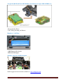
Turnigy 9XR
User Manual
Version 1.1
Page 1
The 9XR is supplied preloaded with top quality software which is full of features and yet
remains easy to use. Our aim was to develop a radio for you, the hobbyist, with an extensive
list of standard features usually expected from a radio system 3 times the price. Our Turnigy
9XR is everything you imagined and more!
For many users this will be the perfect 9 channel radio straight out of the box, We have
factory fitted the 9XR with an AVR ISP header to simplify the development of custom
software, we have launched www.turnigy9xr.com as the epicentre for software developers
and additional community support for all 9XR users.
Version 1.1
Page 2
9XR Standard Features:
• 8 Channel PPM/9 Channel PCM
• Full Ball Bearing gimbals
• Adjustable Stick Length
• Digital Trims on all Primary Axis
• 16 Model Memory
• Assignable Switches
• Freely Assignable Channel Mixes
• Graphical Dual Rate and Exponential
• Sub Trim and Travel Adjust
• Flaps and Differential
• Throttle Hold
• Supports Heli/ Aero/ Glider Model Types
• Programming Templates Based on Model Type• Supports M1, M2, M3, M4 stick modes
• 128 x 64 backlit Liquid Crystal Display
Built in JR & Futaba Trainer Ports
AVR ISP Interface
Version 1.1
Page 3
Accepts the JR Form Factor RF Modules (Orx Dsm2, Orx Open LRS 433Mhz etc)
• Programmable Timers
• Low Voltage Warning and Buzzer
Requires a 3 cell Lipo
• 9XR Firmware Pre-loaded.
• PPM & PCM Output
Includes a internal 2.4GHz Antenna
Online support and user forums available at: www.turnigy9xr.com
Version 1.1
Page 4
Contents
Disclaimer……………………………...................................................………………………........…………………… 7
Introduction………………………………………..........................................................……………….……..……… 8
How the Turnigy Radio Works..………….………………………...............................................................… 9
Definition ……………………………………………………..................................................................…….……… 10
Edit buttons …………………………………………………………........................................................…..…..…… 11
Navigation ……………………………………………………………………....................................................…...….. 11
Editing and Saving …………………………………………………………...................................................…....… 11
On Startup– Quick Model Select ……………………………………..............................................……..….… 12
Transmitter Layout ………………………………………………………………..................................................... 13
Main Screen………………………………………………………………………........................................................ 14
General View………………………………………………………………………...................................................... 14
Statistics Screens Statistics Screens……………………………………………............................................... 15
General Settings…………………………………………………………………....................................................... 16
Radio Setup (1/5) ………………………………………………………………....................................................... 17
Trainer (2/5) ……………………………………………………………………......................................................... 19
Diagnostics (3/5) …………………………………………………………………..................................................... 20
Analog Inputs (4/5) ……………………………………………………………....................................................... 20
Calibration (5/5) ………………………………………………………………........................................................ 21
Model Setup……………………………………………………………………......................................................... 22
Model Select (1/11) ………………………………………………………………................................................... 23
Model Setup (2/11) ………………………………………………………………................................................... 24
Heli Setup (3/11) ………………………………………………………………....................................................... 27
Expo/Dr (4/11) …………………………………………………………………........................................................ 28
Triple Dr Example…………………………………………............................................................................. 28
Mixer (5/11) ……………………………………………………………………........................................................ 29
Main Screen……………………………………………………………………......................................................... 29
Edit Mix……………………………………………………………………................................................................ 30
Limits (6/11) ……………………………………………………………………........................................................ 32
Version 1.1
Page 5
Reverse (7/11) ………………………………………………………………......................................................... 33
Curves (8/11) ……………………………………………………………………..................................................... 33
Custom Switches (9/11) ……………………………………………………….................................................. 35
Safety Switches (10/11) ……………………………………………………….................................................. 36
Templates (11/11) ……………………………………………………………….................................................. 37
Examples: Programming a throttle cut .……….…………………….................................................... 38
Build and Program Instructions …………………………………………………............................................ 41
Building from Source…………………………………………………………..................................................... 41
Flashing…………………………………………………………………………......................................................... 41
Make targets……………………………………………………………………...................................................... 41
Make options……………………………………………………………………...................................................... 41
Software/Firmware Acknoledgements...................................................................................... 42
Version 1.1
Page 6
Disclaimer
THIS FIRMWARE IS PROVIDED ON AN "AS-IS" BASIS WITHOUT WARRANTY OF ANY KIND AND ANY
EXPRESS OR IMPLIED WARRANTIES, INCLUDING, BUT NOT LIMITED TO, THE IMPLIED WARRANTIES
OF MERCHANTABILITY AND FITNESS FOR A PARTICULAR PURPOSE ARE DISCLAIMED. IN NO EVENT
SHALL THE DEVELOPER AND/OR AUTHOR BE LIABLE FOR ANY DIRECT, INDIRECT, INCIDENTAL,
SPECIAL, EXEMPLARY, OR CONSEQUENTIAL DAMAGES (INCLUDING, BUT NOT LIMITED TO:
PERSONAL AND/OR PROPERTY DAMAGE) HOWEVER CAUSED AND ON ANY THEORY OF LIABILITY,
WHETHER IN CONTRACT, STRICT LIABILITY, OR TORT (INCLUDING NEGLIGENCE OR OTHERWISE)
ARISING IN ANY WAY OUT OF THE USE OF THIS FIRMWARE, EVEN IF THE DEVELOPER AND/OR
AUTHOR. HAS BEEN ADVISED BY USER OF THE POSSIBILITY OF SUCH POTENTIAL LOSS OR DAMAGE.
USER AGREES TO HOLD THE DEVELOPER AND/OR AUTHOR. HARMLESS FROM AND AGAINST ANY
AND ALL CLAIMS, LOSSES, LIABILITIES AND EXPENSES.
Version 1.1
Page 7
Introduction
The 9XR is a computerized radio from Turnigy.
The transmitter is outfitted with a 128x64 pixel monochrome back lit LCD, two x 2 axis gimbals,
three variable potentiometers (pots), six 2-position switches, one 3-position switch and Digital
trims.
Version 1.1
Page 8
HowtheTurnigyRadioWorks
Turnigy 9XR Radio flow charts:
The system receives 4 types of inputs:
1. Main Sticks
2. Potentiometers
3. Trims
4. Switches
The analog inputs (sticks and pots) go through a calibration phase, the sticks can also go through
Expo and DR filters before going to the mixer.
The mixer does it all, it directs each input to the desired output (CH1..CH16), it controls how the
inputs are added, it also controls the timing of each function.
After the inputs are processed by the mixer they are directed to the relevant output channels, the
limit procedure takes over and makes sure no output goes too far.
Finally the channels are encoded and sent to the RF module and sent through the air to your
model.
Version 1.1
Page 9
Definitions
Inputs:
1. RUD – Rudder.
2. ELE – Elevator.
3. THR – Throttle.
4. AIL – Aileron.
5. P1/P2/P3 – Pots.
6. Switches:
i. THR – Throttle cut switch, don't confuse this with the THR stick, the TH switch is located on the
back left side.
ii. RUD – Rudder Dual Rate switch.
iii. ELE – Elevator Dual Rate switch.
7. ID0, ID1, ID2 – Three position switch (Flight Mode switch), these 3 define the 3-position
switch, ID0 is the top position, ID1–mid position and ID2–bottom position.
8. AIL – Aileron Dual Rate switch.
9. GEA – Gear switch.
10. TRN – Trainer switch. This switch is spring loaded.
11. SW1..SW6 – Custom switches. More on these later.
It should be stated that every function in this Radio is assignable, there are no fixed switches.
You can choose the TRN switch to be throttle cut and use the triple switch to control DR, the stated
names are useful as they are labeled like that on the Transmitter.
Version 1.1
Page 10
EditButtons
There are 6 edit buttons on the Transmitter, in this manual they are noted with square brackets
([MENU]), some functions need the button to be pressed and held for a second or so. They are
noted as “long”presses like so: [MENU LONG]
The “!” sign - Whenever you see the “!” sign you can read that as “not” or “inverted”, switches can
be“normal” or “inverted”, when choosing the elevator d/r switch ELE is normal operation and !ELE
denotes inverted operation.
Navigation
As a general rule the [UP]/[DOWN]/[LEFT]/[RIGHT] move the cursor appropriately the [MENU] key
is used for selection and for editing, the [EXIT] key is used for exiting, pressing [EXIT] will generally
bring the cursor to the top of the current screen, another press will exit the menu to the main
screen.
Pressing [EXIT LONG] will exit immediately to the main screen.
Pressing [MENU] from the main screen will take you back to the last menu.
From the main screen you can press [RIGHT LONG] to enter the Model setup Menus their are a
total of 11 screens refer to page 22, pressing [LEFT LONG] will enter the Radio setup Menus their
are a total of 5 screens refer to page 17.
Once in the menus you can navigate between different screens using the [LEFT]/[RIGHT] keys as
long as the cursor is at the top right position of the screen.
EditandSaving
As a rule once a value is changed it is saved, you can turn off your Transmitter and turn it back on
and the values will be saved, the values are saved internally in the MCU's eeprom. There may be a
slight delay sometimes so it's probably a good idea to wait a couple of seconds before turning the
radio off.
Note:
There is no undo functionality, once something is erased/changed it's changed for good.
Generally, when a value is highlighted and you cannot move left or right then pressing
[UP]/[DOWN] will change that value.
When moving left or right is possible you need to press [MENU] to edit that value, edit-mode is
displayed by the cursor blinking.
To exit edit-mode press either [MENU] or [EXIT].
It is also possible to change values with the P3 pot (the one at the front of the Transmitter called
PIT. TRIM/AUX 2).
Version 1.1
Page 11
OnStartup–QuickModelSelect
On startup holding a certain key will load an associated model memory, this is useful for quickly
changing between model memories:
• Holding [MENU] Will load Model memory #1
• Holding [EXIT] Will load Model memory #2
• Holding [DOWN] Will load Model memory #3
• Holding [UP] Will load Model memory #4
• Holding [RIGHT] Will load Model memory #5
• Holding [LEFT] Will load Model memory #6
Version 1.1
Page 12
TransmitterLayout
Version 1.1
Page 13
MainScreen
General view
The main view is split into top and bottom, the top contains the following:
•
The current model's name. (GOOFI in this case and yes, it's a real airplane)
•
The battery voltage.
•
Trim increment information.
•
Timer and timer trigger information, pressing [EXIT LONG] resets the timer/ timers.
•
Throttle trim activation information.
The bottom consists of three screens, you can flip between these with the [UP]/[DOWN] keys.
The 3 screens are:
Value bars – these show the output values for the first 8 channels.
Input values – Stick position and switch indicators.
Elapsed timer – Timer that may be started, stopped [MENU] or reset to zero [MENU LONG].
Version 1.1
Page 14
StatisticsScreens
STAT 08:02 TOT
STAT2
TME 08:02 00:00 TSW
tmr 1Lat max 5 us
STK 00:00 00:00 ST%
tmr 1Lat min 5 us
tmr 1 Jitter 0 us
tmain 6,31 ms
Stack 0123 b
From the main screen pressing [UP LONG]/[DOWN LONG] will enter the statistics screen.
The first shows some available timers and traces the throttle stick as well.
The second shows general timing of the Transmitter, the value “tmain” shows how long the math
takes. This will increase as you add more mixers, it can be very large sometimes depending on
eeprom writes.
The Stack value shows the unused space, in hexadecimal, between the end of used Ram memory
and the lowest point the stack has reached, You can reset the timers by pressing [MENU].
Version 1.1
Page 15
GeneralSettings
From the main screen pressing [LEFT LONG] will enter the general settings menus, here you can set
up settings that will be the same regardless of chosen model.
The menus are as follows:
• Radio Setup
• Trainer settings and PPM In Calibration
• Diagnostics
• Analog Inputs
• Calibration
Version 1.1
Page 16
RadioSetup(1/5)
RADIO SETUP
1/5
Owner Name Rob
Beeper
Quiet
Contrast
25
BAT Warning
9.0v
Inactivity Alarm
0n
Mode ↔☼
↕☼
☼↕
☼↔
2 RUD THR ELE AIL
Use this screen to set up general functions for the Transmitter:
1. Owner Name: This will also be displayed on the splash screen.
2. Beeper: Sets Beeping levels
i. Quiet. No beeping at all. No warning – Just remember that the Transmitter will not even warn
you when the battery is low, if you're using a Lipo watch out!
ii. No keys. The beeps are normal but edit keys are silent.
iii. Normal. Normal beeping.
iv. Long beeps. For those who want to annoy other people.
v. Extra long beeps....
3. Contrast: The LCD's contrast. The values can be 20..45.
The higher the value the darker the screen.
4. Battery warning: Battery voltage warning, when the connected battery's voltage drops below
this voltage the Transmitter will beep.
Though the Transmitter will continue to function normally it's advisable to land as soon as
possible.
5. Inactivity alarm: This will set up a warning that will beep if the Transmitter is left unattended for
the specified amount of time, the default value is 10 minutes. To turn off the Inactivity timer –
set the value to zero also when running on USB power, the alarm is inactive. Values can be from
1 to 250 minutes. To reset the timer simply move one of the sticks.
6. Filter ADC:
i. SING: Single conversion. This is the fastest conversion but base resolution is 1024.
ii. OSMP: Oversampling. This uses extra samples to increase resolution to 2048. Just slightly
slower than SING.
iii. FILT: Filtered. This is in case you have excessive noise from the conversion (servo jitters),This
will filter the input and prevent that noise, It will however increase latency by~30msec.
Version 1.1
Page 17
7. Throttle reverse: This is for all you wacky people who fly with the throttle backwards (e.i. idle is
far from you and full is close to you), the reverse will also reverse the throttle warning on
startup and some other throttle related functions.
8. Minute beep: Beeps every full minute while the timer is running.
9. Countdown beep: Beeps at 30, 20, 10, 3, 2 and 1 seconds before the timer ends.
10. Flash on beep: Flashes the backlight on timer beeps.
11. Light switch: This chooses a switch which can be used to turn on the backlight.
12. Light off after: When this is not OFF any keypress will turn on the backlight and turn it off after
the specified number of seconds.
13. Splash screen: Show the logo on radio startup, the splash screen can be skipped on startup by
pressing any key.
14. Throttle warning: If ON will show a warning when throttle is not at idle when the Transmitter is
turned on. The Transmitter will not output a signal until the alert is cleared.
15. Switch warning: If ON will show a warning when the switches are not at the default position
(UP) when the Transmitter is turned on. The Transmitter will not output a signal until the alert
is cleared.
16. Memory warning: If ON will show a warning when the available eeprom memory is less than
200 bytes when the Transmitter is turned on. The Transmitter will not output a signal until the
alert is cleared.
17. Alarm warning: This will give you a “heads up” if your beeper is silent.
If on and the beeper is set to '0' (Quiet) you will receive a warning on startup, this has been
added after a programing session left a user flying on silent. I find it really useful!
18. Mode: Choose between stick modes: MODE1, MODE2, MODE3 and MODE4.
Version 1.1
Page 18
Trainer(2/5)
TRAINER
2/5
mode % src sw
RUD := 100 ch4 TRN
THR := 100 ch3 TRN
ELE := 100 ch2 TRN
AIL := 100 ch1 TRN
Multiplier 1.0
Cal 0.0 0.0 0.0 0.0
This menu allows the PPMin (trainer) inputs to be configured, it enables the RAW PPM inputs to
be selected to replace the sticks for training purposes, the student transmitter does not need to
have the same model setup as the instructor.
All the mixes on the instructors Transmitter will be applied to the student inputs, if for example
you have expo on your sticks this will be applied to the raw trainer inputs when they are selected.
The mode entry selects how the PPMin value is used:
Off unused
+= add to instructor stick value
:= replace instructor stick value
The % entry applies a weighting to the PPMin value -100 to 100, Use -100 to reverse the input,
use values closer to 0 to reduce the students control sensitivity.
The src entry selects the PPMin channel for the function.
The sw entry selects the switch used to action the trainer operation.
Multiplier 1,0 to 5,0 scale for PPMin values
The multiplier does as it's name suggests, it multiplies the ppm Input by a set amount. Great for
dealing with different transmitter's.
CAL Center calibration for first 4 PPMin values
This entry allows you to calibrate the mid point for the first 4 input PPM channels.
Highlighting “Cal” and pressing [MENU] will calibrate the mid point for all PPM IN channels,
PPM IN is read from the signal at the trainer port of the Transmitter.
There is an option for each model to enable or disable the trainer input function, if you do not
need the trainer function you may disable it, and use the selected switch for something else, all
the PPMin values are available to the mixer.
Version 1.1
Page 19
Diagnostics(3/5)
DIAG
THR 0
3/5
RUD 0
Left
0 ELE 0
Right 0 ID1 1 Trim- +
Up
0 ID2 0 ↔☼
0 0
Down
0 AIL 0 ↕☼
0 0
Exit
0 GEA 0 ☼↕
0 0
Menu
0 TRN 0 ☼↔
0 0
This menu will help you visualize the current state of the trims, keys and physical switches, each
Key/Switch/Trim is represented, when pressing a key or switch they are highlighted.
AnalogInputs(4/5)
ANA A1 0422
0
A2 0347
63
A3 0466
0
A4 0414
0
A5 07EE
-30
A6 0345
-30
A7 06AE
80
A8 028B
8,7v
4/5
BG
244
Here you can see the analog inputs in hexadecimal format to save space and annoy you at the same
time, values range between 0..0x7FF (0..2047).
A1..A4 are the gimbals (sticks).
A5..A7 are the pots.
A8 is battery voltage. You can press [DOWN] and highlight the battery voltage, pressing [LEFT]/
[RIGHT] will increase and decrease the value and so enable you to calibrate the battery voltage
monitor.
Version 1.1
Page 20
Calibration(5/5)
CALIBRATION
5/5
START CALIBRATION
[MENU] TO START
This screen allows you to calibrate the analog channels (A1..A7).
The calibration method goes like this:
1. Press [MENU] → (SetMid)
2. Set Sticks to center. (Including throttle and pots)
3. Press [MENU] → (SetSpan)
4. Move sticks and pots through full range.
5. Press [MENU] → (Done) – Values are saved here.
6. Press [MENU] (Back to top)
The values are calculated when you press [MENU].
They are saved when you press [MENU] to (Done).
Version 1.1
Page 21
ModelSetup
From the main screen pressing [LEFT RIGHT] will enter the model select/ settings menus, here you
can setup settings that are model specific.
The menus are as follows:
1. Model Select
2. Model Setup
3. Heli Setup
4. Expo/Dr
5. Mixer (This is the important one)
6. Limits
7. Reverse
8. Curves
9. Custom Switches
10. Safety Switches
11. Templates
Version 1.1
Page 22
ModelSelect(1/11)
MODELSEL free 1560
1/11
*01 Wing Wing
114
02 YAK 55
60
03
04
05
06
In this screen you can see, select, copy and move models between different memory “slots” I
quote the word “slots” because memory management is dynamic, the available memory is
displayed at the top of the screen.
Memory usage for each model is displayed on the right, the more complex your model
(mixes/curves/options/limits/etc) the more memory it'll take.
The “*” on the left shows the currently loaded model memory.
Pressing [UP]/[DOWN] will move the cursor between different models.
Pressing [MENU] will highlight the model, pressing [UP]/[DOWN] with the model highlighted will
move it up/down, Pressing [EXIT] will un-highlight the model.
Pressing [EXIT] will load the highlighted model.
Pressing [EXIT LONG] will load and exit to the main screen.
Pressing [RIGHT LONG] will load the model and go to the next screen (Model Setup).
Pressing [LEFT LONG] will load the model and go to the last screen.
Pressing [MENU LONG] will duplicate the selected model, a confirmation screen will be displayed
requiring you to confirm the duplication of the selected model.
Version 1.1
Page 23
Model Setup (2/10)
SETUP 01
2/11
Name
Wing Wing
Timer
15:00
Trigger
Ths
Trigger B
---
Timer
Count Down
T-Trim
ON
T-Expo
ON
Additional options:
1. Name: Unsurprisingly here you edit the model's name, to edit: scroll down until the name is
highlighted and press [MENU]. Once your press [MENU] only one letter will remain
highlighted, to change the letter you press [UP]/[DOWN]. To move the cursor press
[RIGHT]/[LEFT] Once done, press [MENU]/[EXIT] to exit the edit.
2. Timer: Here you set the value for the timer.
Press [RIGHT]/[LEFT] to choose between minutes and seconds.
Press [MENU] and the cursor will blink, to edit use the [UP]/[DOWN]/[RIGHT]/[LEFT] buttons
and [MENU]/[EXIT] when done.
3. Trigger: Choose what triggers the timer → (remember – by pressing [LEFT] you'll see the same
values with the “!” sign. This means that the usage is inverted)
1. OFF – timer is off.
2. ABS – timer is on.
4. RUs/RU%/ELs/EL%/THs/TH%/ALs/AL% - chooses to activate the timer based on stick position.
When a XXs is selected (THs for example) The timer starts whenever the stick is not at
zero.
The XX% sign is the same except the timer speed is determined by stick position.
When at zero, the timer is stopped, when at full the timer goes at normal speed.
When midway the timer's speed reflects the sticks position.
5. Switches: You can specify a switch so whenever that switch is activated the timer counts.
6. Momentary switches. A switch denoted with “m” (like TRNm) means “ momentary”. That
means that moving the switch once to the on position and back turns the timer on.
Moving it on and off again turns the timer off
7. TriggerB: You can choose a second source to trigger the timer, switches only.
Version 1.1
Page 24
8. Timer: Here you can choose whether the timer counts up or down.
9. T-Trim: Throttle trim. This is a handy feature for power fliers, when activated a couple of things
happen, first off the center detent for the throttle trim is removed the throttle's trim will
now only affect the “low” side, that means you can use the trim for setting idle while full
throttle remains unchanged.
10. T-Expo: another throttle related function, this one makes the throttle stick's expo go from zero
to full instead of having a center like all the others.
11. Trim Inc: Trim increments:
i. Exp – Exponential, with this the trims are fine near the center.
ii. ExFine – Extra fine – 1 step per click.
iii. Fine – 2 steps per click.
iv. Medium (my personal favorite) – 4 steps per click.
v. Coarse – 8 steps per click.
12. Trim Sw: When in flight if this key is activated it reads the current position of the sticks and
trims and copies that into the subtrims, after that it zeros the trims.
This is really usefull for new models when you might have a hard time taking your hands off
the stick and pressing the trims, simply hold the plane level with the sticks and press the
selected trim switch and the plane is trimmed.
13. Beep Cnt: Beep Center. Here you set center warnings, the string RETA123 corresponds to:
RUD, ELE, THR, AIL, P1, P2, P3.
When the letter corresponding to the analog channel is highlighted the system checks for
center. When the input is at center a short beep will sound enabling you to hear when the
input is centered. This is useful for checking the center of the pots without looking.
14. Proto: encoding protocol
i. PPM – with ppm you can choose how many channels to encode, anything from 4 to 16
channels, you can also change the pulse spacing. This is useful for systems which
might experience jitter, used only if last resourt.
ii. Other protocols include Silver A/B/C and TRAC09.
15. Shift Sel: Shift select POS/NEG Select signal shift, POSitive or NEGative.
16. E. Limits: Extended limits, allows limits to go to ±125%
Please test first and make sure this does not cause unwanted mixing between channels.
17. Trainer: Trainer enabled, this allows you to select if the trainer inputs are used on this model.
18. T2thtrig: If t2thtrig is ON, then the second timer will be started when the throttle stick is
moved above about 5%.
This allows the original timer to be used to measure throttle on time (TH%) and the
second timer to give elapsed time, both triggered from the throttle stick.
19. DELETE MODEL [MENU]: This deletes the current model, you need to press [MENU LONG]
Version 1.1
Page 25
WARNING!
Deleting a model causes the memory to jump to the previous model memory in the list, do not
delete a model memory while you have a model "listening" Always shut down your receiver before
deleting a model.
Version 1.1
Page 26
HeliSetup(3/11)
HELI SETUP
3/11
Swash Type
---
Collective
----
Swash Ring
0
ELE Direction
NOR
AIL Direction
NOR
COL Direction
NOR
This screen is specifically designed to help you set up a CCPM heli.
1. Swash Type: This defines what kind of Swash plate you have on your heli:
i. 120: “Standard” 120° swash plate. The “pitch” servo is towards the front/back.
ii. 120X: Same 120° swash plate but turned 90° so the pitch servo is on one side.
iii. 140: 140° swash plate – again, the “pitch” servo is towards the front/back.
iv. 90: 90° - Basically a simple 90° setup where you have a single servo operating the pitch and
two operating the roll.
2. Collective: This defines the collective's source.
The idea being that you can create a mix with all the required curves and switches
and simply plug it in here to mix with the others.
3. Swash Ring: As the name implies, this limits stick movement just like a physical swash ring.
Notice that this only works on AIL and ELE regardless of radio mode selected.
4. ELE/AIL/COL Invert: These invert the direction of the input functions.
Use these to make the controls move the correct way when setting up your
heli.
Version 1.1
Page 27
Expo/Dr(4/11)
EXPO/DR
exp %
sw1 sw2
RUD 0 100 - --- --
THR 50 100 - --- --
ELE 0 100 - --- ---
AIL
4/11
H
H
H
0 100 - --- --- H
This screen allows you to enter and edit Expo and D/R values for the main controls
(RUD/ELE/THR/AIL).
For each control you can input values for Left/Right for both Expo and D/R, to edit expo values
highlight the value in the “expo” column and press [MENU], once the cursor blinks you can use the
[UP]/[DOWN]/[LEFT]/[RIGHT] buttons to change the value.
Notice that while there is a telltale that shows you which side of travel you are adjusting:
• "-”: This means both left and right values are equal. Pressing [UP]/[DOWN]/[LEFT]/[RIGHT]
will change both values simultaneously.
• "←”, “→” : When moving the stick you can see either of these symbols. When this symbol is
visible you are only changing that side of travel.
For each control you can set 2 switches, the main switch changes between high rate/high expo and
mid rate. If the main switch is “low” (e.i. mid rate) the second switch can switch between mid and
low rate.
At the end of each line there's a telltale that shows you which rate you are on:
• H: High.
• M: Medium.
• L: Low.
Pressing [MENU LONG] while the cursor is on a control will take you to the Edit Expo/Dr screen. In
this screen you can adjust the values for that single control.
You will also see a graph indicating the action of that control, press [EXIT] to return to the main
Expo/DR screen.
TripleDRExample
The "F.Mode" switch can be used as a triple rate switch for any one axis, or it can be used as a
triple rate flight mode switch, controlling rates and expos for some or all of the flight axes at once.
To use it as a triple rate/flight mode switch, set sw1 to "!ID2" and sw2 to "!ID1" If you want
Version 1.1
Page 28
rudder, elevator, and aileron all assigned to this switch for flight modes, be sure to set sw1 and sw2
as above for each axis. With the switch in the up position it will be at low rate as indicated by the
"L" at the end of the line. In the mid position it will be mid rate and at the down position, it will be
at high rate. You can also include throttle if you'd like, to have different expo curves for each of the
flight modes.
Mixer(5/11)
The function of the mixer is to take the inputs, perform some function on them and route them to
the output channels, since selection is totally free you have a very flexible system which is
extremely powerful and very quick to boot.
MainScreen
When you enter the screen for the first time you'll probably see a list like so:
MIXER
5/11
CH1 100% THR
CH2 100% AIL
CH3 100% ELE
CH4 100% RUD
CH5 100% FULL
GEA
CH6 100% HALF
ID1
What this is telling you is that the rudder stick's input is being routed with a weight of 100% to
CH1. Same for the elevator, throttle and aileron. Though not visible now you can also see the
switch column which will tell you if a switch is assigned to the mix and also a crv (curve) column
which tells you what curve is applied to that mix.
When you scroll down you'll see that sometimes the weight is being highlighted and sometimes
the channel's number is underlined. When the weight is highlighted, pressing [LEFT]/[RIGHT] will
edit that value and pressing [MENU LONG] will enter the Edit Mix screen and allow you to edit that
mix.
When the channel's number is underlined, pressing [MENU LONG] will insert a new mix for that
channel and take you to the edit mix screen for it.
You can also press [MENU], This will highlight the mix, then you can press [UP]/[DOWN] to move
or copy the mix. Notice that moving or copying is decided by whether you press up or down on the
first press after highlighting the mix. If you first try to move it down it will be copied, subsequent
presses of [UP]/[DOWN] will move the copy up or down until you press [MENU] or [EXIT].
Pressing [UP] will move the mix without copying it, subsequent presses of [UP]/[DOWN] will move
the copy up or down until you press [MENU] or [EXIT].
If the Trainer function is enabled and active, the four values RUD, ELE, THR and AIL are changed to
the PPMin values selected in the TRAINER menu.
Version 1.1
Page 29
EditMix
EDIT MIX CH1
Source
RUD
Weight
100
Offset
0
FlMdoetrim OFF
Trim
ON
Curves
c1
Switch
---
Warning
OFF
In this screen you edit individual mixes.
The available options for each mix:
1. Source: This is the input for the mix it can be the following:
i. Stick or pot: Self explanatory.
ii. HALF: The output is either 0 or the value describes in “weight”. This is controlled by the
switch.
iii. FULL: Same as MAX but the value is “-weight” if the switch is off or “weight” if the
switch is on, MAX and FULL can be a little confusing.
Look in the examples section for, well, examples :)
iv. CYC1, CYC2, CYC3: The 3 outputs of the heli swash-plate mix.
Once swash mixing is turned on (Heli menu – 3/10) these become active and
hold the result of the swash mix. Generally CYC1 holds the fore/aft output
and the other two do the rolling. On the 120X mode CYC1 is the odd one out.
v. PPM1..PPM8: PPM input channels. These are fed by the ppm input or “trainer port”.
You can use these to configure a buddy system or to simply extend your
radio with more functions (like head tracking for you FPV guys).
vi. CH1..CH16: These are the outputs of the other mixes. You can use these to chain mixes
for very complex behavior.
2. Weight: This value multiplies the value from the input. It can be -125% to 125%.
3. Offset: This value is added to the value from the input. It can be -125% to 125%.
4. FlModetrim: If ON, then the offset field is used to store an alternative trim setting (ONLY IF the
mix is active). The trim affected is the one selected by the source for the mix, the mix is really used
to store the new trim info, and does not even need to be on the channel to which the trim is
applied.
Version 1.1
Page 30
So you could set up a mix on any channel like: add ELE weight=0% FlModeTrim ON Switch ID1.
Now, when ID1 is active, the elevator trim switch will modify the offset field in this mix, the value
being used for the trim setting. Switch ID1 off and the trim reverts to the original setting because
the weight is 0, the mix will actually have no effect on the channel to which it is attached.
This description may be as clear as mud, and you won't be able to test it in eepe. An example of
it’s use would be using it as a LAND function, cut the throttle, flip the switch, and use the elevator
trim to set a good glide angle.
5. Trim: When this is “ON” the trim value (if exists) will be carried on through the mix, when“OFF”
it is ignored.
6. Curves:
i. x>0: The value of the source is carried through only if it is positive (greater than zero).
Otherwise it is zero.
ii. x<0: Same but for negative values.
iii. |x|: The value is passed as an absolute value.
iv. f>0: If source is positive then the output value is “+weight” otherwise it is 0.
v. f<0: If source is negative then the output value is “-weight” otherwise it is 0.
vii. c1..c16: custom curves, these are defined in the “CURVES (6/8)” screen. You can also
press [MENU] to edit the curve directly.
7. Switch: Here you select the switch that operates the mix.
If the switch is not selected then the mix is on by default.
8. Warning: Here you can select an audible warning that will sound whenever a mix is active.
(This will only work when a switch is defined). You have an option of 1, 2 or 3 beeps. The
warnings will sound in succession so you can hear them individually.
9. Multpx: This value defines how the mix will be added to the channel.
i. Add: This is the default value, with this value the mix is added to the previous values in
the same channel.
ii. Multiply: Use this to multiply the previous values in the same channel.
iii. Replace: This value is used in conjunction with a switch, when the switch is off the value
is ignored, when the switch is on the value discards the previous values and places
it's own value in the channel.
10. Delay Down/Up: Use this to delay use of this channel, usually used with a switch.
When the switch is turned “ON” or “OFF” the mixer will wait the specified number of
seconds before changing the value.
11. Slow Down/Up: Slow the rate of change in the channel.
When not zero these will determine the maximum speed with which the value can change.
The specified value is the number of seconds to go between -100% to 100%.
12. DELETE MIX [MENU]: Pressing [MENU LONG] here will delete the mix and return to the main
mix screen.
Version 1.1
Page 31
Limits(6/11)
LIMITS
6/11
CH1 -5.9
-100→ 100
CH2 0.7
-100→ 100
CH3 0.0
-95 ← 40
CH4 -14.4 -100→ 100
CH5 45.9
-100→ 100
CH6 0.0
-100→ 100
This is probably the second most important menu.
The limits operate on the output channels (as you can see from the flow chart in the introduction).
In the LIMITS menu you can set the center point (subtrim), limits (both left and right)
Each channel above corresponds to a channel in your receiver, the limits you set will be used on
that channel only.
Columns:
1. subT: SubTrim, this sets the channel's center point.
HINT: The values of subT can be -100 to 100 with increments of 0.1. This is done so to have
excellent resolution when setting the center of each surface. You can use your stick to set the
center point as well, while the subT is highlighted hold the stick so that the surface is centered Press [MENU LONG] and the position will be recorded!
2. Min/Max: These set the endpoints of the channel.
The arrows indecate which side is active at the time for example (CH1 -5.9 -100→ 100), each limit
point can range between -100% to 100%, the limits act both as gains and as absolute limits, the
servo will not go beyond the limits you set here.
Version 1.1
Page 32
Reverse(7/11)
REVERSE
7/11
CH1
NOR
CH2
REV
CH3
NOR
CH4
NOR
CH5
NOR
CH6
NOR
The reverse operate on the output channels and reverse the channel's output (REV – reverse).
1. REV: Reverse, This function reverses the output of the channel - Press [MENU] to trigger.
Curves(8/11)
CURVE
8/11
CV1 -75 -40
0
45 75
CV2
0
0
0
0
0
CV3
0
0
0
0
0
CV4
0
0
0
0
0
CV5
0
0
0
0
0
CV6
0
0
0
0
0
CV7
0
0
0
0
0
In this menu you set your custom curves, curves are nifty things that can tell your servo how to
move when you move your stick, in 9XR there are eight 5-point curves and eight 9-point curves.
A 5pt curve is a curve you can edit at position -100%, -50%, 0%, 50%, 100%.
A 9pt curve is a curve you can edit at position -100%, -75%, -50%, -25%, 0%, 25%, 50%, 75%, 100%.
When you enter the menu you see a long list of zeros, scroll down to the curve you wish to modify
and press [MENU] or [RIGHT], this will bring up the screen for editing the curve.
Version 1.1
Page 33
Depending on whether you chose a 5pt or a 9pt curve you will see 5 or 9 editable points, scroll
through the points with [UP]/[DOWN], change the value with [LEFT]/[RIGHT], At the bottom you
will see a “preset” entry.
Pressing [LEFT]/[RIGHT] on that will populate the values with a linear curve that is a good starting
point.
You can also change the curve graphically, highlight the “EDIT->” line and press [RIGHT], this will
highlight the curve points.
Pressing [UP]/[DOWN] will change the values and pressing [LEFT]/ [RIGHT] will select a different
curve point.
Version 1.1
Page 34
CustomSwitches(9/11)
CUSTOM SWITCHES
9/11
SW1 v<ofs
THR
-60
SW2 ----
----
0
SW3 ----
----
0
SW4 ----
----
0
SW5 ----
----
0
SW6 ----
----
0
Custom switches are not really switches at all but rather a set of logical conditions that can be
used as switches.
Beyond the physical switches there are 6 switches called SW1..SW6, these correspond to the list
you see in this screen, once the condition defined for the switch is met it's value will be“ON”.
1. First we define the condition, This can be v>offset, v<offset, |v|>offset and |v|<offset, or it can
be a logical condition: AND, OR, XOR, or it can be an evaluation between 2 sources.
2. If you've selected a regular condition you need to specify a source and an offset:
i. The source can be a stick, a pot, a PPM input or an output channel.
ii. An offset can be anywhere between -100 and 100, this will be the test point for the condition.
3. If you've selected a logical condition the switch results the condition applied to the 2 selected
switches.
For example: OR ID1 ID2 will be “ON” if either ID1 or ID2 is on.
4. If you've selected an evaluation you (“==”, “>”, “<” etc...) you need to select the 2 sources to
evaluate between.
For example: Switch on only if CH1 is less than RUD → V1<V2 CH1 RUD
Example: Say you have a glow plug driver which you want to turn on when the throttle is below
10%:
1. Highlight SW1
2. Select the source as THR.
3. Select the offset as -80 (remember -100 – 100 so 10% from idle is -80).
4. Select the condition as v<ofs.
Now you need to use a mix to run the switch. Go to the mixer menu, select the CH8 as the channel
you want the GP driver to operate on. On that channel select source as “MAX” and Switch as
“SW1”, now whenever the throttle goes below 10%, CH8 will go to 100%.
Version 1.1
Page 35
Safety Switches (10/11)
SAFETY SWITCHES
CH1 S
---
0
CH2 S
---
0
CH3 S
---
0
CH4 S
---
0
CH5 S
---
0
CH6 S
---
0
10/11
10
Safety switches allow you to select a switch and have it write a value for a channel that will
overwrite any other value.
For example: you might want to set a switch on the channel your electric esc is placed. That way
you can work on your model and not worry that a chance programing error will spin up the
propellor.
This does not make your radio fool proof!
You must be careful at all times, hopefully this can add another level of safety and reduce the risks
associated with this hobby.
Version 1.1
Page 36
Templates(11/11)
TEMPLATES
11/11
11
01 Simple 6-ch
02 T-Cut
03 V-Tail
04 Elevon/Delta
05 Heli Setup
Channel Order RETA
CLEAR MIXES [MENU]
The templates are there to help you get started, when entering the screen you'll see a list of
available templates. To choose a template, scroll down to it and press [MENU LONG], this will add
the template to the existing mixes.
Channel order:
This will allow you to set the way the templates are written to the mixers.
RETA means RUD = 1, ELE = 2, THR = 3, AIL = 4.
AETR means AIL = 1, ELE = 2, THR =3, RUD = 4.
At the bottom you'll see an option called “CLEAR MIXES [MENU]” - Pressing [MENU LONG] on this
will clear all the mixes leaving you with a clean slate.
The templates are:
1. Simple 6-CH: Plain vanilla 6-ch airplane.
2. T-Cut: This adds a throttle cut mix on your throttle channel.
3. V-Tail.
4. Elevon\Delta.
5. Heli Setup: This will clear your mixes and curves and setup a preliminary eCCPM heli.
6. Gyro Setup: Once you have the gyro setup, setup your Transmitter so that the stick direction
is correct.
Just like a flybarless system you are not controling the servo directly the gyro's head holding ability
and your ability to make yaw changes are two seperate operation as far as the gyro is concerned.
7. Servo Test: This will setup a servo test output on CH15 to test your servos choose the
mixer's source as CH15, it will cycle slowly between -100 and 100.
Version 1.1
Page 37
Examples
Programming a throttle cut
Though you can use a template for this it's instructional to do it via the mixer.
Start off with the default 6 mixes.
Scroll down until CH1 is underlined, as per the example below:
MIXER
5/11
CH1 100% THR
CH2 100% AIL
CH3 100% ELE
CH4 100% RUD
CH5 100% FULL
GEA
CH6 100% HALF
ID1
Press [MENU LONG] to enter the “Insert/Edit Mix” screen.
EDIT MIX CH1
Source
THR
Weight
100
Offset
0
FlMdoetrim OFF
Trim
ON
Curves
c1
Switch
---
Warning
OFF
Version 1.1
Page 38
Change source to “FULL” and Weight to “-100”.
Also set the Switch to THR:
EDIT MIX CH1
Source
MAX
Weight
-100
Offset
0
Trim
ON
Curves
---
Switch
THR
Warning
OFF
Keep on scrolling down until you reach Multpx.
Change the value to “Replace”
EDIT MIX CH1
Weight
-100
Offset
0
Trim
ON
Curves
---
Switch
THR
Warning
OFF
Multpx
Replace
Version 1.1
Page 39
Now press [EXIT]
You should see the following screen:
MIXER
5/11
CH1 100% THR
R-100% FULL THR
CH2 100% AIL
CH3 100% ELE
CH4 100% RUD
CH5 100% FULL
GEA
CH6 100% HALF
ID1
What it tells you is that on CH3 you have 2 mixes defined.
The first takes the value of the throttle stick and the second depends on the THR switch.
When the switch is off the mix is ignored so the only value will be the value of the throttle stick.
When the switch is on that value will be replaced with -100%.
Version 1.1
Page 40
ThisSectionisforAdvancedUsers/Programmers
BuildandProgramInstructions
You might want to play with the code and modify the 9XR to suit your own needs, It's
helpfull if you know a little C programing.
First to program the MCU download the full programing instructions: Flashing the 9x by Jon Lowe.
BuildingfromSource
Please refer to www.turnigy9xr.com for the latest 9XR source code.
Flashing
(you may have to run as admin to access the USB port in Linux)
To write the FW: make wflash AVRDUDE_PROGRAMMER=usbasp
To write the EEPROM: make weeprom AVRDUDE_PROGRAMMER=usbasp
To read FW: make rflash AVRDUDE_PROGRAMMER=usbasp TARGET=backupflash
To read the EEPROM: make reeprom AVRDUDE_PROGRAMMER=usbasp TARGET=backupeeprom
Make sure you replace "usbasp" with the name of your programmer.
To list available programmers type: avrdude -c ?
make targets
• make all (default): build the source
• make clean: Remove compiled files and directories.
• make wflash: Write flash (program) memory.
• make rflash: Read flash memory.
• make weeprom: Write eeprom.
• make reeprom: Read eeprom.
• make coff: Convert ELF to AVR COFF.
• make extcoff: Convert ELF to AVR Extended COFF.
• make debug: Start either simulavr or avarice as specified for debugging, with avr-gdb or avrinsight as the front end for debugging. (for debug info look into the makefile)
• make filename.s: Just compile filename.c into the assembler code only.
make options
• EXT=JETI: make jeti vesion.
• AVRDUDE_PROGRAMMER: Set avr programmer name - default: usbasp (to list all available:
avrdude -c ?)
• TARGET: Set target name - default: tgy-9XR
• OPT: Set optimization level - default: s
• FORMAT: Set format (can be srec, ihex, binary) - default: ihex
• MCU: Set MCU - default: atmega64
Version 1.1
Page 41
Software/Firmware Acknowledgements
Turnigy wishes to acknowledge the ongoing development work by the authors of the original
source code and the 9x community.
The 9XR firmware has been developed as a fork of the original 9x firmware and as such will
continue to be developed alongside the 9x and open/9x codes.
The firmware is an Open Source project, you are free to look up, download, modify and release the
code under the GNU v2 software license.
If you have any questions, requests or suggestions, the best place to express them is either on the
firmware‘s page: www.turnigy9xr.com/index.php
Bug reports and enhancement requests can be reported here: http://forum.turnigy9xr.com/index.php
eePe and er9x are free to use under the GNU v2.0 License, use, copy and modify
it as you wish.
SOURCE CODE And Code Development
The 9XR source code is available for download at http://turnigy9xr.com/source/tgy-9XRv1-1.rar
If you feel you'd like to contribute time, software code, documentation, tutorials or real world
programming examples; feel free to share it with the R/C community via the Turnigy 9XR forum.
If you have written software that you feel should be featured on the site, please email us
at:[email protected]
We will feature your firmware variations at turnigy9xr.com as free community software, and if it
makes the grade we will certify it as approved 9XR firmware.
We look forward to seeing the 9XR embraced for what it is, that is the peoples radio, and look
forward to watching the software develop alongside new hardware solutions as they become
available.
The Turnigy 9XR Hardware Development Team thanks you for your support.
Version 1.1
Page 42