1
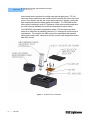
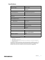
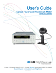
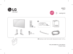
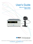
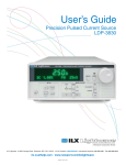
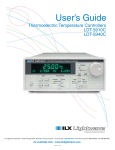
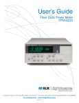
User’s Guide Laser Diode Mount LDM-4990 ILX Lightwave · 31950 Frontage Road · Bozeman, MT, U.S.A. 59715 · U.S. & Canada: 1-800-459-9459 · International Inquiries: 406-556-2481 · Fax 406-586-9405 ilx.custhelp.com · www.newport.com/ilxlightwave 700391_01 August 2013 TA B L E O F C O N T E N T S TABLE OF CONTENTS Safety Information and the Manual . . . . . . . . . . . . . . . . . . . . . . . . . . . . . . . . . v General Safety Considerations . . . . . . . . . . . . . . . . . . . . . . . . . . . . . . . . . . . . v Safety Marking Symbols . . . . . . . . . . . . . . . . . . . . . . . . . . . . . . . . . . . . . . . . . vi Comments, Suggestions, and Problems . . . . . . . . . . . . . . . . . . . . . . . . . . . viii Chapter 1 Introduction and Specifications Product Overview . . . . . . . . . . . . . . . . . . . . . . . . . . . . . . . . . . . . . . . . . . . . . . . . 1 Specifications . . . . . . . . . . . . . . . . . . . . . . . . . . . . . . . . . . . . . . . . . . . . . . . . . . . 3 Chapter 2 Operation LDM-4990 Mount Electrical Connections . . . . . . . . . . . . . . . . . . . . . . . . . . . . . 5 Configuring the LDM-4990 . . . . . . . . . . . . . . . . . . . . . . . . . . . . . . . . . . . . . . . . . 8 Laser Diode Mounting . . . . . . . . . . . . . . . . . . . . . . . . . . . . . . . . . . . . . . . . . . . . 10 Current Sources and Current Measurements . . . . . . . . . . . . . . . . . . . . . . . . . 12 Temperature Control . . . . . . . . . . . . . . . . . . . . . . . . . . . . . . . . . . . . . . . . . . . . . 12 Thermoelectric Temperature Control . . . . . . . . . . . . . . . . . . . . . . . . . . . . . . 12 Water Cooling . . . . . . . . . . . . . . . . . . . . . . . . . . . . . . . . . . . . . . . . . . . . . . . . 13 Nitrogen Purge . . . . . . . . . . . . . . . . . . . . . . . . . . . . . . . . . . . . . . . . . . . . . . . 14 Installing OMH-6700 Series Measurement Heads . . . . . . . . . . . . . . . . . . . . . 16 Chapter 3 Maintenance Chapter 4 Safety 09_07 LDM-4990 i TA B L E O F C O N T E N T S ii LDM-4990 LIST OF FIGURES LIST OF FIGURES Figure 1.1 Exploded View of LDM-4990 . . . . . . . . . . . . . . . . . . . . . . . . . . . . 2 Figure 2.1 LDM-4990 Laser Mount Connections . . . . . . . . . . . . . . . . . . . . . 6 Figure 2.2 Laser Current Connector . . . . . . . . . . . . . . . . . . . . . . . . . . . . . . . 6 Figure 2.3 LDM-4990 TEC Connector . . . . . . . . . . . . . . . . . . . . . . . . . . . . . 7 Figure 2.4 Configuration Switch Labels . . . . . . . . . . . . . . . . . . . . . . . . . . . . 8 Figure 2.5 Laser Diode Pin Assignment . . . . . . . . . . . . . . . . . . . . . . . . . . . . 9 Figure 2.6 LDM-4990 Access Door Device Selector . . . . . . . . . . . . . . . . . 10 Figure 2.7 Installation of a 9.0 mm Window Can Laser . . . . . . . . . . . . . . . 11 Figure 2.8 LDM-4990 Water Connections . . . . . . . . . . . . . . . . . . . . . . . . . 14 Figure 2.9 Nitrogen Purge Connection . . . . . . . . . . . . . . . . . . . . . . . . . . . . 15 Figure 2.10 Installing the OMH-6700 Measurement Head . . . . . . . . . . . . . 16 09_07 LDM-4990 iii LIST OF FIGURES iv LDM-4990 SAFETY AND WARRANTY INFORMATION The Safety and Warranty Information section provides details about cautionary symbols used in the manual, safety markings used on the instrument, and information about the Warranty including Customer Service contact information. Safety Information and the Manual Throughout this manual, you will see the words Caution and Warning indicating potentially dangerous or hazardous situations which, if not avoided, could result in death, serious or minor injury, or damage to the product. Specifically: Caution indicates a potentially hazardous situation which can result in minor or moderate injury or damage to the product or equipment. Warning indicates a potentially dangerous situation which can result in serious injury or death. WARNING Visible and/or invisible laser radiation. Avoid direct exposure to the beam. General Safety Considerations If any of the following conditions exist, or are even suspected, do not use the instrument until safe operation can be verified by trained service personnel: • Visible damage • Severe transport stress • Prolonged storage under adverse conditions • Failure to perform intended measurements or functions If necessary, return the instrument to ILX Lightwave, or authorized local ILX Lightwave distributor, for service or repair to ensure that safety features are maintained (see the contact information on page viii). All instruments returned to ILX Lightwave are required to have a Return Authorization Number assigned by an official representative of ILX Lightwave Corporation. See Returning an Instrument on page vii for more information. LDM-4990 v SAFETY SYMBOLS SAFETY SYMBOLS This section describes the safety symbols and classifications. Technical specifications including electrical ratings and weight are included within the manual. See the Table of Contents to locate the specifications and other product information. The following classifications are standard across all ILX Lightwave products: • Indoor use only • Ordinary Protection: This product is NOT protected against the harmful ingress of moisture. • Class I Equipment (grounded type) • Main supply voltage fluctuations are not to exceed ±10% of the nominal supply voltage. • Pollution Degree II • Installation (overvoltage) Category II for transient overvoltages • Maximum Relative Humidity: <80% RH, non-condensing • Operating temperature range of 0 °C to 40 °C • Storage and transportation temperature of –40 °C to 70 °C • This equipment is suitable for continuous operation. Safety Marking Symbols This section provides a description of the safety marking symbols that appear on the instrument. These symbols provide information about potentially dangerous situations which can result in death, injury, or damage to the instrument and other components. Caution, refer to manual Earth ground Terminal Alternating current Visible and/or invisible laser radiation Caution, risk of electric shock Protective Conductor Terminal Caution, hot surface Frame or chassis Terminal On: In position of a bistable push control. The slash (I) only denotes that mains are on. or (I) vi LDM-4990 Off: Out position of a bistable push control. The circle (O) only denotes that mains are off. or (O) WA R R A N T Y WARRANTY ILX LIGHTWAVE CORPORATION warrants this instrument to be free from defects in material and workmanship for a period of one year from date of shipment. During the warranty period, ILX will repair or replace the unit, at our option, without charge. Limitations This warranty does not apply to fuses, lamps, defects caused by abuse, modifications, or to use of the product for which it was not intended. This warranty is in lieu of all other warranties, expressed or implied, including any implied warranty of merchantability or fitness for any particular purpose. ILX Lightwave Corporation shall not be liable for any incidental, special, or consequential damages. If a problem occurs, please contact ILX Lightwave Corporation with the instrument's serial number, and thoroughly describe the nature of the problem. Returning an Instrument If an instrument is to be shipped to ILX Lightwave for repair or service, be sure to: 1 Obtain a Return Authorization number (RA) from ILX Customer Service. 2 Attach a tag to the instrument identifying the owner and indicating the required service or repair. Include the instrument serial number. 3 Attach the anti-static protective caps that were shipped with the instrument and place the instrument in a protective anti-static bag. 4 Place the instrument in the original packing container with at least 3 inches (7.5 cm) of compressible packaging material. Shipping damage is not covered by this warranty. 5 Secure the packing box with fiber reinforced strapping tape or metal bands. 6 Send the instrument, transportation pre-paid, to ILX Lightwave. Clearly write the return authorization number on the outside of the box and on the shipping paperwork. ILX Lightwave recommends you insure the shipment. If the original shipping container is not available, place your instrument in a container with at least 3 inches (7.5 cm) of compressible packaging material on all sides. Repairs are made and the instrument returned transportation pre-paid. Repairs are warranted for the remainder of the original warranty or for 90 days, whichever is greater. Claims for Shipping Damage When you receive the instrument, inspect it immediately for any damage or shortages on the packing list. If the instrument is damaged, file a claim with the carrier. The factory will supply you with a quotation for estimated costs of repair. You must negotiate and settle with the carrier for the amount of damage. 09_07 LDM-4990 vii WA R R A N T Y Comments, Suggestions, and Problems To ensure that you get the most out of your ILX Lightwave product, we ask that you direct any product operation or service related questions or comments to ILX Lightwave Customer Support. You may contact us in whatever way is most convenient: Phone . . . . . . . . . . . . . . . . . . . . . . . . . . . (800) 459-9459 or (406) 586-1244 Fax . . . . . . . . . . . . . . . . . . . . . . . . . . . . . . . . . . . . . . . . . . . . . (406) 586-9405 On the web at: . . . . . . . . . . . . . . . . . . . . . . . . . . . . . . . . . . . . ilx.custhelp.com Or mail to: ILX Lightwave Corporation P. O. Box 6310 Bozeman, Montana, U.S.A 59771 www.ilxlightwave.com When you contact us, please have the following information: Model Number: Serial Number: End-user Name: Company: Phone: Fax: Description of what is connected to the ILX Lightwave instrument: Description of the problem: If ILX Lightwave determines that a return to the factory is necessary, you will be issued a Return Authorization (RA) number. Please mark this number on the outside of the shipping box. You or your shipping service are responsible for any shipping damage when returning the instrument to ILX Lightwave; ILX recommends you insure the shipment. If the original shipping container is not available, place your instrument in a container with at least 3 inches (7.5 cm) of compressible packaging material on all sides. viii LDM-4990 CHAPTER 1 INTRODUCTION AND SPECIFICATIONS This manual describes the LDM-4990 TO-Can Mount Laser Diode Mount and related accessories and options and explains their operation. This chapter provides an overview of the LDM-4990 and contains general information and specifications important in its use. You should read the entire manual to familiarize yourself with the operation of your LDM-4990 Laser Diode Mount before installing laser diodes. In particular, you should read the section on Electrical Connections before installing a laser diode. The information contained in this section is necessary to provide correct electrical connection to your particular laser. Product Overview The LDM-4990 Laser Diode Mounting Fixture provides a compact, easy to use instrument for 9 mm, 5.6 mm and 5.4 mm packaged laser diodes. This mounting fixture features an access door for easy device insertion and clamping, and easy interchange between the packages without socket changes. The LDM-4990 can also be quickly configured for three and four pin devices regardless of their pin assignments through dip switches located next to the laser mounting plate. The fixture offers active temperature control with an integrated thermoelectric module and water cooling channels for a temperature control range of -20ºC to +85ºC. High positional and thermal resistance repeatability ensure consistent device testing and repeatable laser measurements. The LDM-4990 facilitates power and wavelength measurement with an optional rotating mounting post for mounting and locating ILX Lightwave OMH-6700 Series measurement heads directly above the laser. A ball plunger detent locks the head in place for consistent placement of the measurement head over the laser diode. Power and wavelength measurements can be made with the OMM-6810B Power Meter or the LPA-9080 Series Laser Parameter Analyzer. The LDM4990 is quick to set up with connectors for laser current and temperature control, a ground post for laser diode static protection during insertion and LDM-4990 1 CHAPTER 1 INTRODUCTION AND SPECIFICATIONS Product Overview removal and hose connectors for cooling water and nitrogen purge. TO-Can lasers are simply inserted into the socket under the access door on the top of the mount. Once seated, and with the correct device selector in position, closing the door locates and forces the diode against the hotplate. The LDM-4990 mount allows direct interfacing to most ILX Lightwave current sources and temperature controllers through standard ILX current and temperature control cables. The LDM-4990 is intended for applications where a TO-can-type laser diode needs to be tested and is especially suited for L-I-V testing over a wide range of temperatures. For example, the 4990 would aid in experiments that measure optical power output from a laser as a function of case or die temperature and/or laser drive current. Figure 1.1 Exploded View of LDM-4990 2 LDM-4990 Specifications Laser Packages 9mm, 5.6mm, 5.4mm Laser Lead Length 6.4mm to 19mm Laser Pin-out1 Common cathode or common anode, three and four pin devices Input Connectors Laser Diode Current ILX standard female 9-pin D-sub Case Temperature Control ILX standard male 9-pin D-sub Ground Female banana jack Laser Diode Maximum Laser Diode Current 4.0A Case Temperature Control2 Temperature Control Range 000Water Cooling3,4 -20oC to 85oC 000Natural Convection +10oC to 85oC Maximum Thermal Load 500 mW Sensor Type AD590JH, Calibrated Accuracy +0.5oC TE Module Ratings 4A @ 8.5V General Size (H x W x D) 4.75” x 4” x 1.5” (120.6 mm x 101.6 mm x 381 mm) Weight 2.4 lbs. (1.1 kg) 3.1 lbs. (1.4 kg) with EMS499 Regulatory Compliance RoHS EMS-499 Power Measurement Option ILX Measurement Head Compatibility OMH-6703, 6708B, 6722B, 6727B, 6732B 1. Selectable with configuration header 2. At 25oC ambient 3. Tested with 8L/minute water flow, 10oC 4. Water temperatures below 10oC will cause condensation on the mounting fixture. ILX recommends maintaining water temperatures above 10oC Our goal is to make the best laser diode instrumentation available anywhere. To achieve this, we need your ideas and comments on ways we can improve our products. We invite you to contact us at any time with your suggestions. LDM-4990 3 CHAPTER 4 LDM-4990 1 INTRODUCTION AND SPECIFICATIONS Specifications CHAPTER 2 OPERATION This chapter describes the electrical connection to and operation of the LDM-4990 TO-Can Laser Diode Mounting Fixture. Configuration options for the LDM-4990 and various laser package mounting is also discussed. The LDM-4990 is shipped from the factory with no configuration set for the laser pin-out. Operation of your laser will be impossible without first configuring the LDM-4990. Before installing your laser, please read the sections in this chapter for details on how to do this. See the section "Configuring the LDM-4990" for pin assignments. LDM-4990 Mount Electrical Connections There are three connectors on the LDM-4990 as shown in Figure 2.1. The laser current source connector is a female 9-pin D-sub connector, shown as P1. The temperature controller connector is a male 9-pin D-sub connector, shown as P2. P3 is a ground connector for grounding the mount. LDM-4990 5 CHAPTER 2 OPERATION LDM-4990 Mount Electrical Connections Figure 2.1 LDM-4990 Laser Mount Connections The female 9-pin connector (P1) for the laser current is compatible with all ILX Lightwave current sources and cables. There are connections provided for laser cathode and anode, photodiode cathode and anode, and ground. The pinout diagram for this connector is shown in Figure 2.2. Figure 2.2 Laser Current Connector When connecting cables to the LDM-4990, tighten cable connectors to the mount connectors. Loose connectors can cause contact bounce which may result in transients and potential damage to laser diodes. 6 LDM-4990 Proper shielding of the current source and temperature controller signals is necessary to ensure proper noise-free performance. This is accomplished by grounding the shield on the interconnect cables to the controller and not to the mount. The CC-505 Temperature Control Cable provides this shielding automatically by connecting the 15 pin housing into the temperature controller. The CC-305S Current Source Cable, being symmetrical, must be oriented correctly to ensure proper grounding of the shield. This is done by connecting the serial-number end of the cable to the current source. The current source will still drive the laser normally with the cable reversed, but the noise performance will be degraded. If noise becomes excessive during testing, check the orientation of your laser cable. The male 9-pin connector (P2) for temperature control is compatible with all ILX Lightwave temperature controllers and cables. There are connections provided for TE module (+) and (-), and thermistor (two connections). The pinout diagram for this connector is shown in Figure 2.3. Figure 2.3 LDM-4990 TEC Connector LDM-4990 7 CHAPTER 2 OPERATION Configuring the LDM-4990 Configuring the LDM-4990 The LDM-4990, as shipped from the factory, is not configured for any laser. Therefore, the mount must be configured for your particular laser before operation. There is no real standard for pin numbering of these devices; most three pin devices are similar if not identical, however, some four-pin devices are numbered opposite. Because of this, use caution when configuring the 4990 as the pin numbers shown on the diode mounting plate are arbitrary and may not correspond with the pin number on the diode's data sheet. To configure the 4990 for a particular laser package, open the access cover to access the bank of configuration switches. There are 16 total switches as shown in Figure 2.4, divided up between four laser package functions, i.e., LD + (anode), LD- (cathode), PD+(anode), PD- (cathode). Any laser package function can be assigned to switch 1 through 4 (S1 - S4), which corresponds to the number as labeled on the diode mounting plate (and do not correspond with the laser diode package pin-out). Figure 2.4 Configuration Switch Labels 8 LDM-4990 OPERATION Configuring the LDM-4990 CHAPTER 2 For example, Figure 2.5 shows a TO-can laser with its associated pin assignments and configuration. The pins are assigned as shown in Table 2.1. Figure 2.5 Laser Diode Pin Assignment Table 2.1 Sample Pin Assignments Type A Type B Pin 1 Case LD Anode/Case Pin 2 LD Cathode LD Cathode Pin 3 PD Anode PD Anode Pin 4 LD Anode/PD Cathode PD Cathode For each type, the LDM-4990 configuration switches would be set as follows: Table 2.2 Sample LDM-4990 Pin Configuration LD+ S1 Type A Type B 09_07 S2 S3 LDS4 X X S1 S2 S3 PD+ S4 S1 S2 PD- S3 S4 S1 S2 S3 S4 X X X X X X LDM-4990 9 CHAPTER 2 OPERATION Laser Diode Mounting Laser Diode Mounting Laser diodes are extremely susceptible to damage caused by electrostatic discharge and surge currents. To avoid early failure or damage to the device, workers and workbenches must be grounded at all times when handling or working with laser diodes. The LDM-4990 is designed to allow quick, easy insertion and removal of laser diodes in a 5.4 mm, 5.6 mm and 9.0 mm TO-can style package. A unique access door with a rotating device selector on the inside allows configuration of the mount for any of these package styles; Figure 2.6. DEVICE SELECTOR Figure 2.6 LDM-4990 Access Door Device Selector To adjust the 4990 for your device package, simply rotate the device selector so that the correct o-ring is to the right and the device selector clicks in place. The large o-ring is for 9 mm packages, the next counterclockwise position for 5.6 mm packages, the final position is for 5.4 mm packages. For correct positioning of the device selector be sure to rotate it two clicks between positions. Be sure the mount is configured correctly for the can style before attempting to close the access door. Incorrect configuration may damage the mount or the device. 10 LDM-4990 OPERATION Laser Diode Mounting CHAPTER 2 To install a laser diode, refer to Figure 2.7, and follow these steps: 1 Ensure that the mount has been configured for the correct pin-outs for the laser you are about to install. If it has not been configured, refer to instructions earlier in this chapter for more information. 2 Disable the output of any current controller connected to the mount. 3 Open the access door. 4 Identify pin 1 of the laser and orient the diode with pin one to the left as marked on the laser mounting plate. 5 Insert the laser through the hole in the laser mounting plate, and into the test socket. Ensure that the laser pins uniformly engage the socket. 6 Push down on the diode so that it seats against the laser mounting plate. 7 Close the access door and push on the door to insure the door is locked in place. If you feel any unusual resistance when closing the door, open the door and check to see that the device selector is in the correct position for your particular device. Figure 2.7 Installation of a 9.0 mm Window Can Laser After the device is inserted into the socket, close the access door and push down until it clicks in place. Make sure the access door locks in place; this provides positive pressure on the laser diode. 09_07 LDM-4990 11 CHAPTER OPERATION Current Sources and Current Measurements 2 Current Sources and Current Measurements Do not exceed the specified current settings of the laser. Excessive drive current may cause laser failure. Operate the LDM-4990 Laser Diode Mount using any ILX Lightwave current source or temperature controller. Operation with other current sources or temperature controllers is also possible, provided that the correct wiring is observed (refer to Figures 2.4 and 2.5). If an ILX Lightwave current source is used with the system interlock feature, the interlock connections are available at pins 1 and 2 of the current source connector (see Figure 2.2). With the ILX Lightwave interlock feature enabled, the interlock pins must be connected before current can flow from the source to the laser diode. Do not exceed the specified maximum drive current of the laser. If you are using an ILX Lightwave current source, or any other current source which has an adjustable limit setting, be sure to set the current limit to a safe level for your laser. If it is necessary to measure the current of your laser during operation, follow these steps: 1 NEVER connect an ammeter in series with the laser circuit. 2 Place a known resistance (1 ohm works well) in series with the laser diode circuit. Then, measure the voltage across the resistor. Calculate the current by using Ohm's Law, I = E/R. 3 NEVER turn the voltmeter on or off, or change the voltage measurement range, while current is flowing to the laser. These actions could result in failure of your laser diode. ILX Lightwave current sources allow the user to read the output current during laser operation. Therefore, if you are using an ILX Lightwave current source, it is not necessary to measure the laser current as described above. Temperature Control Thermoelectric Temperature Control The operating characteristics of diode lasers vary considerably with temperature. Emission wavelength, threshold current and operating lifetime all are strong functions of device temperature. For a typical diode laser emitting 3 mW at 780 nm, the emission wavelength will shift an average of 0.26 nm/°C and the threshold current will shift an average of 0.3 mA/°C. In addition, the operating lifetime drops by a factor of two for every 25°C rise in operating temperature. Thermoelectric 12 LDM-4990 OPERATION Temperature Control CHAPTER 2 (Peltier) devices provide a simple, reliable solution to precise temperature control in many applications of optoelectronic devices. These solid-state devices can heat or cool small thermal loads to more than 60°C from ambient and achieve temperature stabilities of better than 0.001°C. Active temperature control of the LDM-4990 is accomplished with two thermoelectric modules and a temperature measurement element using a thermistor for real-time feedback to a thermoelectric temperature controller such as an ILX Lightwave LDT-5948. The actual temperature is measured by the temperature sensor. This temperature is then compared to a set-point temperature, to produce an error signal proportional to the difference between setpoint and actual temperature. The temperature controller outputs a proportional bi-directional current to the thermoelectric modules depending on the direction of the error. Thermal resistance, measured in °C/W, between the laser package and the laser plate results in a temperature difference between the laser plate and laser diode. The laser plate is gold plated for better thermal conductivity. Caution must be used when placing a laser diode in the mount and removing it not to scratch the surface between the laser and the laser plate. Scratches and contamination of the surface will degrade the thermal performance of the mount resulting in an increase of the thermal resistance between the laser and laser plate. Water Cooling The LDM-4990 is configured for use as a natural or forced convection heat sink using chilled water. Water cooling allows lowering the operating temperature of the laser case to -20°C by providing higher heat dissipation than natural convection. Water cooling the 4990 is accomplished by attaching the brass water fittings supplied in the shipping kit to the LDM-4990. A forced flow of 10°C water is adequate for cooling the mount to -20°C. If higher performance is required, the flow and/or the water temperature (through a chiller) can be adjusted. Use caution when cooling the flow water below 10°C. Condensation may form on the 4990 housing and internal components. To install water fittings, refer to Figure 2.8, and follow these steps: 09_07 1 Remove two black plastic hole plugs at the back of the mount on both sides of the 9-pin connectors. 2 Apply teflon tape or a pipe sealant to the threads of each fitting, and thread them into the LDM-4990 13 CHAPTER OPERATION Temperature Control 2 mount. Use a ½" open-end wrench to tighten the fittings. Use caution when tightening the fittings to avoid damaging the threads in the 4990 fixture. 3 Connect 1/4" I.D. flexible tubing to each fitting and to a water source and drain. Figure 2.8 LDM-4990 Water Connections Nitrogen Purge As the temperature within the LDM-4990 is driven to near ambient and below, the problem of condensation around the laser device and mount becomes a concern. This environmental problem has been addressed by the use of a nitrogen purge system designed into the mounting fixture. This purge system ventilates the inner cavity of the LDM-4990, preventing condensation on the laser diode and the surrounding components. To flow nitrogen through the LDM-4990, a 1/16" OD nipple is provided on the back of the mount, (see Figure 2.9) above the laser current and temperature controller connectors. Connect 1/8" OD plastic tubing on to the nipple and push over the flare to prevent the tubing from disconnecting or leaking under pressure. 14 LDM-4990 OPERATION Temperature Control CHAPTER 2 Figure 2.9 Nitrogen Purge Connection 09_07 LDM-4990 15 CHAPTER OPERATION Installing OMH-6700 Series Measurement Heads 2 Installing OMH-6700 Series Measurement Heads The EMS-499 Measurement Head Option allows you to attach some OMH-6700 Series Measurement heads to the LDM-4990 for power and wavelength measurement of the device under test. To install an OMH-6700 Measurement Head, refer to Figure 2.10, and follow these steps: 1 Align the flat on the 6700 measurement head with the flat on the mounting post of the 4990 with the aperture facing down. 2 Insert the #6-32 x 1" attaching screw supplied with the 4990 through the countersunk hole in the mounting post and thread into the measurement head. 3 Tighten the screw with a 9/64" allen head wrench. Note: Use caution when tightening the screw into the measurement head to avoid damaging the threads. Figure 2.10 Installing the OMH-6700 Measurement Head 16 LDM-4990 CHAPTER 3 MAINTENANCE No maintenance procedures are required for the LDM-4990 other than an occasional cleaning, as needed, to remove any accumulated dust or dirt from the hot plate. If the mount is not in use with a laser inserted, the access door should be closed. Insert plastic anti-static covers over the 9-pin laser current and temperature control connectors. LDM-4990 17 CHAPTER 18 LDM-4990 3 MAINTENANCE CHAPTER 4 SAFETY Laser diodes used with the LDM-4990 Laser Diode Mount may emit infrared radiation which is invisible to the human eye. Extreme care must be taken to prevent the beam from being viewed either directly or through external optics or mirrors. Remove rings, jewelry, and other reflective materials when working with lasers. WARNING Viewing of emissions from the laser may cause eye damage. Use of protective goggles is recommended when operating these lasers. Use of controls or adjustments or performance of procedures other than those specified herein may result in hazardous radiation exposure. This product conforms to all applicable DHHS regulations 21 CFR Subchapter J, at the date of manufacture. LDM-4990 19 CHAPTER 20 LDM-4990 4 SAFETY