1
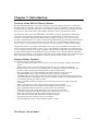
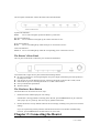
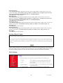
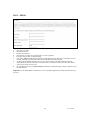
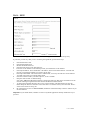
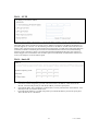
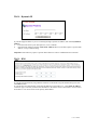
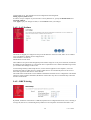
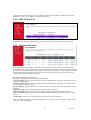
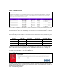
Wireless-B Broadband Router
User’s Manual
Version 1.0
Trademarks
Microsoft, Windows, and Windows NT are registered trademarks of Microsoft Corporation.
Other brand and product names are registered trademarks or trademarks of their respective holders.
Statement of Conditions
In the interest of improving internal design, operational function, and/or reliability, we reserves the right to make
changes to the products described in this document without notice. We does not assume any liability that may occur
due to the use or application of the product(s) or circuit layout(s) described herein.
Federal Communications Commission (FCC) Compliance Notice: Radio Frequency Notice
This equipment has been tested and found to comply with the limits for a Class B digital device, pursuant to part 15 of
the FCC Rules. These limits are designed to provide reasonable protection against harmful interference in a residential
installation. This equipment generates, uses, and can radiate radio frequency energy and, if not installed and used in
accordance with the instructions, may cause harmful interference to radio communications. However, there is no
guarantee that interference will not occur in a particular installation. If this equipment does cause harmful interference
to radio or television reception, which can be determined by turning the equipment off and on, the user is encouraged to
try to correct the interference by one or more of the following measures:
•Reorient or relocate the receiving antenna.
•Increase the separation between the equipment and receiver.
•Connect the equipment into an outlet on a circuit different from that to which the receiver is connected.
•Consult the dealer or an experienced radio/TV technician for help.
FCC Caution
1.
2.
3.
FCC RF Radiation Exposure Statement: The equipment complies with FCC RF radiation exposure limits set forth
for an uncontrolled environment. This equipment should be installed and operated with a minimum distance of 20
centimeters between the radiator and your body.
This Transmitter must not be co-located or operating in conjunction with any other antenna or transmitter.
Changes or modifications to this unit not expressly approved by the party responsible for compliance could void
the user authority to operate the equipment.
EN 55 022 Declaration of Conformance
This is to certify that the Router is shielded against the generation of radio interference in accordance with the
application of Council Directive 89/336/EEC, Article 4a. Conformity is declared by the application of EN 55 022 Class
B (CISPR 22).Compliance with the applicable regulations is dependent upon the use of shielded cables. It is the
responsibility of the user to procure the appropriate cables.
1
User’s Manual
About This User Manual
Welcome to the Networking world of the Wireless Router!
This manual is intended as a basic introduction to your Wireless Router. It provides enough information to
make the Router operational in most common environments: connecting to the Internet, create your own
private network and share an Internet connection.
We'll describe how to use your web browser to configure the Router and to perform some basic operations,
e.g. upgrading the software, or viewing the connection log, a task which may be useful in ongoing
operations. Finally, we'll tell you how to obtain information and help for subjects that are beyond the scope
of this manual.
This manual consists of four chapters and two appendixes
Chapter One: Introduction, explains the features and capabilities of the Router.
Chapter Two: Connecting the Router, gives the simple steps for you to follow to connect the Router with
PCs and modem.
Chapter Three: Configuring the PCs, describes how to configure each of your PCs to be able to
communicate with the Router.
Chapter Four: Configuring the Router, explains how to login to user interface, describes the browser
screen, and provides the needed steps to configure your Router for specific applications. It provides
easy-to-follow instructions for quick Internet access and provides guidelines to the most popular Router
configurations.
Chapter Five: Wireless Configuration, describes how to configure the wireless features of your Router
Chapter Six: Advanced Configuration, provides information on advanced configurations.
Appendix A: Troubleshooting
Appendix B: Specifications
Safety Warnings
The Router is not intended to be serviced by the user. Do not open the case
2
User’s Manual
Contents
Chapter 1-Introduction
Overview of the 802.11b Wireless Router
Wireless Router Features
The Router’s Front Panel
The Router’s Rear Panel
The Hardware Reset Button
5
5
5
6
6
6
Chapter 2-Connecting the Router
What you need to do before you begin
Connecting wired PC to the Router
Connecting wireless PC to the Router
7
7
7
8
Chapter 3-Configuring the PCs
Configuring Windows 98 and Windows Me PCs
Configuring Windows 2000 PCs
Configuring Windows XP PCs
9
9
10
11
Chapter 4-Configuring the Router
Using the Setup Wizard
14
14
Chapter 5-Wireless Configuration
Guidelines to locate your Router
Understanding the wireless security
Understanding the wireless settings
Configuring the basic wireless settings
Configuring WEP
19
19
19
19
23
23
Chapter 6-Advanced Configuration
Advanced Setup
System - System Time
System - Administrator Settings
System - Firmware Update
System - Configuration Tools
System - Status
System - Security Log
System - Reset System
WAN Setting
WAN - PPPoE
WAN - PPTP
WAN – L2TP
WAN - Static IP
WAN - Dynamic IP
WAN - DNS
WAN - Dynamic DNS
WAN - Proxy DNS
LAN - LAN Settings
LAN - DHCP Setting
LAN - DHCP Client List
NAT - Special Application
NAT - Virtual Server
Firewall Setting
Firewall - Client Filtering
24
24
25
25
26
26
27
27
28
28
29
30
31
31
32
32
33
33
34
34
35
35
36
36
37
3
User’s Manual
Firewall - URL Filtering
Firewall - DMZ (Demilitarized Zone)
Appendix A Troubleshooting
Appendix B Specifications
37
38
39
40
4
User’s Manual
Chapter 1: Introduction
Overview of the 802.11b Wireless Router
Wireless-B Broadband Router is the perfect solution for connecting multiple computers to a high-speed
Broadband Internet connection. This router is combined with a 4-port 10/100 Mbps switch for connection
to create a home or small office network, an access point for wireless network, one 10/100 Mbps Ethernet
WAN port for a DSL/Cable modem, and an Internet firewall for security against Internet hackers.
The Router has built-in 4-port auto-MDI/MDIX 10/100 Mbps switch, this cutting-edge combination of
router and switch technology eliminates the need to buy an additional hub or switch and serves your
network as a completely dedicated, full duplex backbone. Built-in a wireless access point, the Router
provides a maximum data rate of 11 Mbps, with 64-bit/128-bit WEP Encryption and MAC address filtering
for wireless LAN security. It provides you an easy, wireless way to connect multiple computers in your
house or office. You can enjoy the freedom of wireless LAN from anywhere in and around the building.
The Router provides a 10/100 Mbps Ethernet WAN port as well as Network Address Translation (NAT)
function, which provides the ability to share a DSL or Cable Modem through either its four Ethernet ports
or via its integrated wireless access point. It employs a Dynamic Host Configuration Protocol (DHCP) that
provides dynamic allocation of IP addresses for up to 253 clients on your network. Designed with MIPS
based processor, the Router is an incredibly faster router with more than 60 Mbps LAN to WAN throughput.
Being independent of platform, the Router is an ideal networking solution for PC or Mac users.
Wireless Router Features
The Router provides the following features:
- All-in-one networking solution provides wireless access point, IP sharing, switching, and firewall
security.
- MIPS based processor provides incredibly performance power for wireless AP and Router.
- Built-in wireless access point connects multiple 802.11b-equipped computers without wires and
provides seamless roaming within the IEEE 802.11b WLAN infrastructure.
- More than 60Mbps LAN to WAN throughput eliminates bottleneck of Internet access.
- Auto-MDI/MDIX feature on WAN and LAN ports detect and correct cable error.
- 10/100Mbps Ethernet WAN port connects DSL/Cable modem for high speed Internet sharing access.
- 4-port auto-negotiation 10/100Mbps switch connects multiple computers or another Ethernet network.
- Universal Plug and Play provides easy setup.
- Built-in NAT function allows multiple PCs (up to 253 users) and devices to share one Internet
connection.
- Built-in NAT function provides firewall protection against outside intruders.
- 60-bit/128-bit WEP encryption and MAC address filtering provide wireless security.
- High compatibility design and smart set-up wizard ensure easy installation.
- L2TP, PPTP, IPSec Pass Through VPN allows server-client secure connection.
- Virtual Server/DMZ allows multimedia applications and Internet servers on LAN.
- MAC address and IP packet filtering enhance transmission security.
- MAC clone meets specific ISP's requirement for Internet sharing.
- Smart Web-based setup wizard provides easy installation.
- Platform-independent ensures full compatibility with PC or Mac.
The Router’s Front Panel
5
User’s Manual
The front panel of the Router contains the status LEDs described below.
System LED Indicators:
Power
Green. This LED lights up when the Router is powered on.
WLAN LED Indicators:
WLAN
Green. When the LED lights up, the wireless network is active.
WAN LED Indicators:
WAN
Green. The LED lights up when WAN port is connected to a device.
LAN LED Indicators:
LAN1~4 Green. The LED lights up when the corresponding port is connected to a device.
The Router’s Rear Panel
The rear panel of the Router contains the port connections listed below.
Viewed from left to right, the rear panel contains the following features:
DC power connector for connecting through an AC power adapter (included as part of the product) to
the wall power outlet
Four local (LAN) 10/100 Ethernet ports for connecting the Router to the local PCs or hub, switch
Ethernet WAN port for connecting the Router to a Cable or DSL modem
Factory Default Reset push button
Wireless antenna
The Hardware Reset Button
The Reset button can be used in one of two ways:
1.
Reboot the Router while keeping all of its settings.
If the Router is having problems connecting to the Internet, press the Reset button for just a moment
with a paper clip or a pencil tip. This clears up any jammed connections.
2.
Restore the Router’s factory defaults and clear all of its settings, including a new password or wireless
settings.
If you are experiencing extreme problems with the Router and have tried all other troubleshooting
measures, press the Reset button and hold it down for 10 seconds.
Chapter 2: Connecting the Router
6
User’s Manual
This chapter describes how to connect the Router to your local area network (LAN). You will have to
configure your networked PCs to accept the IP addresses that the Router assigns them, and you will also
have to configure the Router with settings provided by your Internet Service Provider (ISP).
The installation technician from your ISP should have left the setup information for your modem with you
after installing your broadband connection. If not, you can call your ISP to request that data. Once you have
the setup information you need for your broadband connection, you can begin installation and setup the
Router.
If you want to use a PC with an Ethernet adapter to configure the Router, go to “Connecting wired PC to
the Router”. If you want to use a PC with a wireless adapter to configure the Router, go to “Connecting
wireless PC to the Router”.
What you need to do before you begin
Before connecting the Router, it’s highly recommended to connect your PC to the modem directly, and
make sure you can get on the Internet without problem.
Connecting wired PC to the Router
Follow these steps to connect wired PC to the Router.
1.
Power on the Router and modem, and make sure all of your PCs are powered off.
2.
Connect one end of an Ethernet cable to one of the LAN ports on the rear of the Router, and the other
end to an Ethernet port on a PC. (Repeat this step to connect more PCs, a switch, or other network
devices to the Router)
3.
Connect a different Ethernet cable from your Cable or DSL modem to the EWAN port on the rear of
the Router.
7
User’s Manual
Modem
4.
Power on all of your PCs. If all of your Link LEDs are not lighting up, make sure that all your cables
are securely plugged in, and that all of your hardware is powered on properly.
Connecting wireless PC to the Router
Follow these steps to connect wireless PC to the Router.
1.
2.
3.
4.
Power on the Router and modem, and make sure all of your PCs are powered off.
Connect an Ethernet cable from your Cable or DSL modem to the EWAN port on the rear of the
Router.
Power on all of your PCs on the wireless network.
For initial access to the Router through a wireless connection, make sure the PC’s wireless adapter has
its SSID set to WLAN (the Router’s default setting), and its WEP encryption is disabled. After you
have accessed the Router, you can change the Router and this PC’s adapter settings to match your
usual network settings.
Chapter 3: Configuring the PCs
8
User’s Manual
This chapter describes how to configure each of your PCs to be able to communicate with the Router.
To do this, you need to configure your PC’s network settings to obtain an IP address automatically, so your
PC can function as a DHCP client.
Configuring Windows 98 and Windows Me PCs
1.
Click the Start button, select Settings and then Control Panel. Double-click the Network icon.
2.
On the Configuration tab, select the TCP/IP line for the applicable Ethernet adapter. Do not choose a
TCP/IP entry whose name mentions PPPoE, VPN..etc. If the word TCP/IP appears by itself, select that
line. Click the Properties button.
1
2
3.
Click the IP Address tab, select Obtain an IP address automatically.
9
User’s Manual
4.
5.
6.
Click the Gateway tab, and verify that the Installed Gateway field is blank. Click the OK button.
Click the OK button again. Windows may ask you for the original Windows installation CD or
additional files. Check for the files at c:\windows\options\cabs, or insert your Windows CD-ROM into
your CD-ROM drive and check the correct file location, e.g., D:\win98 (if “D” is the letter of your
CD-ROM drive).
Windows may ask you to restart your PC. Click the Yes button. If Windows does not ask you to restart,
restart your PC anyway.
Go to “Chapter 4: Configuring the Router”
Configuring Windows 2000 PCs
1.
Click the Start button, select Settings and then Control Panel. Double-click the Network and
Dial-up Connections icon.
2.
Select the LAN Area Connection icon for the applicable Ethernet adapter. Right-click the icon, then
click the Properties option.
Make sure the box next to Internet Protocol (TCP/IP) is checked. Highlight Internet Protocol
(TCP/IP), and click the Properties button.
3.
10
User’s Manual
4.
Select Obtain an IP address automatically and Obtain DNS server address automatically. Once
the new window appears, click the OK button. Click the OK button again to complete the PC
configuration.
1
2
3
5.
Restart your PC.
Go to “Chapter 4: Configuring the Router”
Configuring Windows XP PCs
1.
Click the Start button, select Settings and then Control Panel. Double-click the Network
Connections icon.
11
User’s Manual
2.
3.
Select the Local Area Connection icon for the applicable Ethernet adapter. Right-click the Local
Area Connection, then click the Properties option.
Make sure the box next to Internet Protocol (TCP/IP) is checked. Highlight Internet Protocol
(TCP/IP), and click the Properties button.
2 (TCP/IP)
1
4.
3
Select Obtain an IP address automatically and Obtain DNS server address automatically. Once
the new window appears, click the OK button. Click the OK button again to complete the PC
configuration.
1
12
2
User’s Manual
Go to “Chapter 4: Configuring the Router”
Chapter 4: Configuring the Router
13
User’s Manual
Once you have completed all the hardware installation and have configured your PCs properly as described
in chapter three, you are ready to configure the Router for actual applications.
The instructions from your ISP tell you how to set up your PC for Internet access. Because you are now
using the Router to share Internet access among several PCs, you will use the setup information to
configure the Router instead of your PC. You only need to configure the Router one time by using one of
the PC you set up.
Using the Setup Wizard
The Setup Wizard will guide you step by step to configure the Router.
1.
Connect to the Router by typing http://192.168.62.1 in the address field of Internet Explorer or
Netscape Navigator.
2.
A setup screen will appear. Click Setup Wizard.
3.
For security reason, the Router has its own user name and password. When prompted, enter admin for
the user name and 1234 for the password. Click OK button.
14
User’s Manual
User name: admin
Password: 1234
4.
Select the time zone for your location. If your location experiences daylight saving, check the box next
to Daylight Saving. Click NEXT button.
5.
Based on the setup instructions from your ISP, you need to select one of WAN connection types. The
Router supports five connection types: PPPoE, PPTP, L2TP, Static IP Address, and Dynamic IP
Address. Each setup screen and available features will differ depending on what kind of connection
type you select.
15
User’s Manual
PPPoE
If your DSL provider says that you are
connecting through PPPoE, perform these
steps:
a. Enter the User Name
b. Enter the Password
c. Reenter the password
d. Enter the Service Name if your ISP
requires it. This is optional.
e. Keep the value of MTU as default
setting.
Note: MTU (Maximum Transmission
Unit) is the largest frame size that can
be transmitted over the network.
Messages longer than the MTU must
be divided into smaller frames.
f. To change the maximum idle time, enter a new value in minutes. This determines how long the Router
keeps the Internet connection active after there is no Internet activity from the LAN. Enter a value of
zero means never log out.
g. By checking the box next to Auto-reconnect, the Router will automatically connect to Internet if you
are disconnected.
Important: If you enable PPPoE, remember to remove any PPPoE applications already installed on any of
your PCs.
PPTP
Point to Point Tunneling Protocol
(PPTP) is a service that applies to
connections in Europe only.
If your DSL provider says that you are
connecting through PPTP, perform
these steps:
a.
b.
c.
d.
e.
f.
g.
h.
i.
j.
Enter the PPTP Account
Enter the PPTP Password
Reenter the PPTP Password
Enter the Host Name if your ISP
requires it.
Enter Service IP Address. Your ISP
will provide you with the Service IP
Address.
Enter My IP Address. This is the
Router’s IP address, when seen
from the Internet. Your ISP will
provide you with the IP Address
you need to specify here.
Enter My Subnet Mask. This is the Router’s subnet mask, as seen by external users on the Internet.
Your ISP will provide you with the subnet mask.
Enter the Connection ID if your ISP requires it, or leave it blank.
Keep the value of MTU as default setting.
Note: MTU (Maximum Transmission Unit) is the largest frame size that can be transmitted over the
network. Messages longer than the MTU must be divided into smaller frames.
To change the maximum idle time, enter a new value in minutes. This determines how long the Router
16
User’s Manual
keeps the Internet connection active after there is no Internet activity from the LAN. Enter a value of
zero means never log out.
k. By checking the box next to Auto-reconnect, the Router will automatically connect to Internet if you
are disconnected.
Important: If you enable PPTP, remember to remove any PPTP applications already installed on any of
your PCs.
L2TP
Select this option when your ISP uses
L2TP. Choose “Obtain an L2TP Server
IP address automatically” if your ISP
supports it, or choose “Use the
following L2TP Server IP address” and
fill in the L2TP Server IP address.
Then, enter the L2TP User Name and
Password assigned by your ISP. Enter a
Maximum Idle Time (in minutes) to
define a maximum period of time for
which the Internet connection is
maintained during inactivity. If the
connection is inactive for longer than
the defined Maximum Idle Time, then connection will be dropped. You can enable the Auto-reconnect
option to automatically re-establish the connection as soon as you attempt to access the Internet again.
Static IP Address
If you are required to use a
permanent IP address to
connect to the Internet, then
select Static IP Address.
a. Enter the IP address
assigned by your ISP.
This is the Router’s IP
address, when seen from
the Internet. Your ISP
will provide you with the
IP address you need to specify here.
b. Enter Subnet Mask. This is the Router’s subnet mask, as seen by external users on the Internet. Your
ISP will provide you with the subnet mask.
c. Enter ISP Router Address. Your ISP will provide you with the IP address you need to specify here.
This is the ISP server’s IP address.
Dynamic IP Address
If your ISP supports DHCP or you
are connecting through a dynamic IP
address, then select Dynamic IP
Address.
a. Enter the Host Name if your ISP
requires it, or leave it blank.
b. Enter the MAC Address and
click Clone MAC Address
button if your ISP requires a
specific MAC address, or keep it default setting.
Important: Some ISPs may require a specific MAC address in order to establish Internet connection.
17
User’s Manual
Click APPLY button when completing the selected WAN Setting.
6.
If your ISP will automatically assign DNS IP addresses to the Router, keep the default setting here,
then click NEXT button.
If your ISP does not automatically assign DNS IP addresses to the Router (e.g., when Static IP
Address connection type is selected), enter the DNS IP address in the filed of Primary DNS address
and Secondary DNS address. You need to enter at least primary DNS address. Click FINISH button to
complete setup wizard.
18
User’s Manual
Chapter 5: Wireless Configuration
This chapter describes how to configure the wireless features of your Router. In planning your wireless
network, you should consider the level of security required. You should also select the appropriate
placement of your Router in order to maximize the wireless performance.
Guidelines to locate your Router
The operating distance or range of your wireless connection can vary significantly based on the physical
placement of the Router. For best performance, place your Router:
Near the center of the area in which your PCs will operate.
Away from sources of interfaces, such as PCs, microwaves, and 2.4GHz cordless phones.
Away from large metal surfaces.
Understanding the wireless security
Unlike wired network data, your wireless data transmissions can be received well beyond your walls by
anyone with a compatible adapter. For this reason, use the security features of your wireless devices. The
Router provides effective security features which are covered in detail in this chapter.
There are several ways you can implement the security of your wireless network.
Restrict access based on MAC address. The wireless MAC filters feature allows you to control
which wireless-equipped PCs may or may not communicate with the Router depending on their MAC
addresses. MAC address filtering adds an obstacle against unwanted access to your network, but the
data broadcast over the wireless link is fully exposed.
WEP. Wired Equivalent Privacy (WEP) is an encryption method used to protect your wireless data
communications. WEP uses 64-bit or 128-bit keys to provide access control to your network and
encryption security for every data transmission. To decode data transmissions, all wireless devices
must use an identical WEP key. Higher encryption levels offer higher levels of security, but due to the
complexity of the encryption, they may decrease network performance.
Understanding the wireless settings
To configure the wireless setting of the Router, click “Advanced Setup”, key-in user name and password,
click “LAN” then “Wireless” link in the menu of the browser interface. The wireless settings menu will
appear, as shown below.
19
User’s Manual
Enable Wireless. If you disable the wireless, wireless devices cannot connect to the Router.
ESSID. The Extended Service Set Identifier (ESSID) is the network name shared among all devices in
a wireless network. The ESSID must be identical for all devices in the wireless network. It is
case-sensitive and must not exceed 32 alphanumeric characters, which may be any keyboard character.
Make sure this setting is the same for all devices in your wireless network.
Channel. This field determines which operating frequency will be used. It should not be necessary to
change the wireless channel unless you notice interference problems with another nearby access point
or wireless router.
Beacon Interval. The default value is 100. Enter a value between 1 and 65,535 milliseconds. The
Beacon Interval value indicates the frequency interval of the beacon. A beacon is a packet broadcast by
the Router to synchronize the wireless network.
RTS Threshold. This value should remain at its default setting of 2432. The range is 256 ~ 2432 bytes.
Should you encounter inconsistent data flow, only minor modifications are recommended. If a network
packet is smaller than the present RTS threshold size, the RTS/CTS mechanism will not be enabled.
The Router sends Request to Send (RTS) frames to a particular receiving station and negotiates the
sending of a data frame. After receiving an RTS, the wireless station responds with a Clear to Send
(CTS) frame to acknowledge the right to begin transmission.
Fragmentation Threshold. This value should remain at its default setting of 2346. The range is 256 ~
2346 bytes. It specifies the maximum size for a packet before data is fragmented into multiple packets.
If you experience a high packet error rate, you may slightly increase the Fragmentation Threshold.
Setting the Fragmentation Threshold too many may result in poor network performance. Only minor
modifications of this value are recommended.
DTIM Interval. The default value is 1. This value, between 1 and 65,535 milliseconds, indicates the
interval of the Delivery Traffic Indication Message (DTIM). A DTIM field is a countdown field
20
User’s Manual
informing clients of the next window for listening to broadcast and multicast messages. When the
Router has buffered broadcast or multicast messages for associated clients, it sends the next DTIM
with a DTIM Interval value. Its clients hear the beacons and awaken to receive the broadcast and
multicast messages.
Max Stations. The default value is 250. This value, between 1 and 254, represents the maximum
number of wireless clients, which are allowed to connect with the Router.
Basic Rates. Shows the set of rates reported as Basic Rates.
TX Rates. Shows the set of Transmission Rates.
Preamble Type. The preamble defines the length of the CRC block for communication between the
Router and a wireless network adapter. (High network traffic areas should use the short preamble type.)
In most cases, keep default setting as Long Preamble.
Authentication Type. The default is set to Both, which allows either Open System or Shared Key
authentication to be used. For Open System authentication, the sender and the recipient do not use a
WEP key for authentication. For Shared Key authentication, the sender and recipient use a WEP key
for authentication.
21
User’s Manual
Encryption. The default setting is Disable, which means no encryption will be applied. If WEP is
enabled, you can manually or automatically program the encryption keys. These values must be
identical on all wireless devices in your wireless network.
There are two levels of WEP encryption, 64-bit and 128-bit. Higher encryption level offers higher level
of security, but due to the complexity of the encryption, they may decrease network performance.
There are two methods for creating WEP encryption keys:
- Automatically. Enter a word or group of printable characters in the Passphrase box and click the
Generate button. These characters are case sensitive.
- Manually. There are two different key formats, Alphanumeric (also called ASCII) and
Hexadecimal. For 64-bit WEP, enter 5 characters in Alphanumeric format, or 10 digits (any
combination of 0-9, a-f, or A-F) in Hexadecimal format. For 128-bit WEP, enter 13 characters in
Alphanumeric format, or 26 digits (any combination of 0-9, a-f, or A-F) in Hexadecimal format.
- Default TX Key. Select which WEP Key (1~4) will be used when the Router sends data. Make
sure the receiving device is using the same key.
Wireless Access Control. Click on button to set the authorized MAC addresses list. Only the devices
on the Wireless Control List will be allowed to wirelessly connect to the Router.
Enhanced Security. Check the box to hide the SSID or block the unspecified SSID. When wireless
clients survey the local area for wireless networks to associate with, they will detect the SSID
broadcasted by the Router. To broadcast the Router’s SSID, keep the default setting. If you do not want
to broadcast the Router’s SSID, then check the box next to hide the SSID.
22
User’s Manual
Configuring the basic wireless settings
Follow the instructions below to set up and test basic wireless connectivity. Once you have established
basic wireless connectivity, you can enable security settings appropriate to your needs.
1. Connect to the Router at its default IP address of http://192.168.62.1, or using whatever LAN IP
address you have set up.
2. Click “Advanced Setup”, then key-in default user name of “admin” and default password of “1234”,
or using whatever password you have set up.
3. Click “LAN” in the main menu, and then click “Wireless”.
4. Make sure the box next to “Enable Wireless” is checked.
5. Choose a suitable description name for the wireless network name (ESSID) or keep it default. In the
ESSID box, enter a value of up to 32 alphanumeric characters.
6. Set the Channel or keep it default. The default channel is 6.
7. Keep all other fields in default settings.
8. Click “APPLY” button to save your changes.
9. Configure and test your PCs for wireless connectivity. Check the wireless adapter of your PCs to have
a wireless link and are able to obtain an IP address by DHCP from the Router.
Once your PCs have basic wireless connectivity to the Router, then you can configure the advanced
wireless security functions of the Router.
Configuring WEP
Follow the instructions below to set up WEP data encryption:
Important! If you use a wireless PC to configure WEP settings, you will be disconnected when you click
on APPLY. You must then either configure your wireless adapter to match the Router WEP settings or
access the Router from a wired PC to make any further changes.
1.
2.
3.
4.
5.
6.
7.
8.
Connect to the Router at its default IP address of http://192.168.62.1, or using whatever LAN IP
address you have set up.
Click “Advanced Setup”, then key-in default user name of “admin” and default password of “1234”,
or using whatever password you have set up.
Click “LAN” in the main menu, and then click “Wireless”.
Click “Security Setting”.
Check the box next to
“Enable”, and click “Set
WEP Keys”.
Form the setup screen, select
the level of WEP encryption
you wish to use, 64 Bit or 128
Bit.
You can automatically or
manually program the
encryption keys. These values
must be identical on all PCs
and Router.
- Automatic: Enter a word or group of printable characters in the Passphrase box and click the
Generate button. These characters are case sensitive.
- Manually: There are two different key formats, Alphanumeric (also called ASCII) and
Hexadecimal. For 64-bit WEP, enter 5 characters in Alphanumeric format, or 10 digits (any
combination of 0-9, a-f, or A-F) in Hexadecimal format. For 128-bit WEP, enter 13 characters in
Alphanumeric format, or 26 digits (any combination of 0-9, a-f, or A-F) in Hexadecimal format.
- Default TX Key: Select which WEP Key (1~4) will be used when the Router sends data. Make
sure the receiving device is using the same key.
Click “Apply” button to save your settings.
23
User’s Manual
Chapter 6: Advanced Configuration
Advanced Setup
The advanced setup menu is used to configure the LAN and WAN settings, as well as other advanced
functions such as resetting the router, restoring to factory default settings, hosting services and upgrading to
newer version of firmware, client filtering and special applications. For the instructions below to enter into
the Advanced Setup:
1.
Connect to the Router at its default IP address of http://192.168.62.1, or using whatever LAN IP
address you have set up.
2.
Click “Advanced Setup”, then key-in default user name of “admin” and default password of
“1234”, or using whatever password you have set up.
24
User’s Manual
System - System Time
Set the time zone for the Router and connecting to a Simple Network Time Protocol (SNTP) server which
allows the Router to synchronize the system clock to the global Internet. The synchronized clock in the
Router is used to record the security log and control client filtering.
System - Administrator Settings
Use this menu to restrict management access based on a specific password. The default password is 1234.
Passwords can contain from 3-12 alphanumeric characters, and are case sensitive.
Idle Time-out - The amount of time of inactivity before the Router will automatically close the
Administrator session.
Remote Management – Using the Remote Management feature, you can allow a remote administrator on
the Internet to configure, upgrade and check the status of your Router.
To configure your Router for Remote
Management:
1. Check the box next to “Enable”.
2. Specify the IP address which will be
allowed to access the Router.
3. Click “APLLY” button to have
your settings take effect.
Note:
1. When accessing your Router from
the Internet, you will type your Router’s
Specify the IP address of a remote administrator’s PC
25
User’s Manual
2.
WAN IP address into the browser’s address of remote administrator, followed by a colon ‘:’ and the
custom port number.
For example, if Router’s WAN IP
address is 210.61.49.227, you must
enter http://210.61.49.227:8080 in the browser of remote administrator.
To view the Router’s WAN IP address, you can check it from the Status screen.
System - Firmware Update
The Router software (firmware) is stored in flash memory, and can be upgraded as new firmware is
released. Upgrade files can be downloaded from vendor’s website. If the file is compressed (.ZIP file), you
must first extract the .IMG file before loading to the Router.
Click “Browse..” button to load the firmware file then click “APPLY” button. You will be prompted to
confirm the upgrade.
System - Configuration Tools
Check the box next to “Restore Factory Default Configuration” then click “APPLY” button to reset all
configuration settings to their default values. Any settings you have saved will be lost when the default
settings are restored. This feature is disabled by default.
26
User’s Manual
System - Status
You can use the Status screen to see the connection status for the Router’s WAN/LAN interfaces.
System - Security Log
You may choose to Enable or Disable the Log feature. Click Apply to put your changes in effect, or click
Cancel to undo your changes.
27
User’s Manual
Session Event Log
Click Session Event Log to launch the Session Event Log Table window. In this screen, you can view
session event entries. The Session Event Log Table shows Index number, Transport Type, Source IP,
Source Port, Destination IP, Destination Port, and Terminate Reason.
Click Refresh to see the latest data.
Block Event Log
Click Block Event Log to launch the Block Event Log Table window. In this screen, you can view
blocking event entries. The Block Event Log Table shows Index number, Transport Type, Source IP,
Source Port, Destination IP, Destination Port, and Termination Reason.
Click Refresh to see the latest data.
Intrusion Event Log
Click Intrusion Event Log to launch the Intrusion Event Log Table window. In this screen, you can view
intrusion event entries. The Intrusion Event Log Table shows Index number, Record Time, and
Intrusion Type.
Click Refresh to see the latest data.
Wireless Event Log
Click Wireless Event Log to launch the Wireless Event Log Table window. In this screen, you can view
wireless event entries. The Wireless Event Log Table shows Index number, Time, Severity, and
Description.
Click Refresh to see the latest data.
System - Reset System
In the event that the Router stops responding correctly or in some way stops functioning, you can perform a
reset. Your settings will not be changed. To perform the reset, click on the "Reset" button below. You will
be asked to confirm your decision. The reset will be complete when the power light stops blinking.
WAN Setting
28
User’s Manual
WAN - PPPoE
If your DSL provider says that you are connecting through PPPoE, perform these steps:
a.
Enter the User Name
b.
Enter the Password
c.
Reenter the password
d.
Enter the Service Name if your ISP requires it. This is optional.
e.
Keep the value of MTU as default setting.
f.
Note: MTU (Maximum Transmission Unit) is the largest frame size that can be transmitted over the
network. Messages longer than the MTU must be divided into smaller frames.
g.
To change the maximum idle time, enter a new value in minutes. This determines how long the
Router keeps the Internet connection active after there is no Internet activity from the LAN. Enter a
value of zero means never log out.
h.
By checking the box next to Auto-reconnect, the Router will automatically connect to Internet if you
are disconnected.
Important: If you enable PPPoE, remember to remove any PPPoE applications already installed on any of
your PCs.
29
User’s Manual
WAN - PPTP
Point to Point Tunneling Protocol (PPTP) is a service that applies to connections in Europe only.
If your DSL provider says that you are connecting through PPTP, perform these steps:
a.
b.
c.
d.
e.
f.
g.
h.
i.
j.
k.
Enter the PPTP Account
Enter the PPTP Password
Reenter the PPTP Password
Enter the Host Name if your ISP requires it.
Enter Service IP Address. Your ISP will provide you with the Service IP Address.
Enter My IP Address. This is the Router’s IP address, when seen from the Internet. Your ISP will
provide you with the IP Address you need to specify here.
Enter My Subnet Mask. This is the Router’s subnet mask, as seen by external users on the Internet.
Your ISP will provide you with the subnet mask.
Enter the Connection ID if your ISP requires it, or leave it blank.
Keep the value of MTU as default setting.
Note: MTU (Maximum Transmission Unit) is the largest frame size that can be transmitted over the
network. Messages longer than the MTU must be divided into smaller frames.
To change the maximum idle time, enter a new value in minutes. This determines how long the
Router keeps the Internet connection active after there is no Internet activity from the LAN. Enter a
value of zero means never log out.
By checking the box next to Auto-reconnect, the Router will automatically connect to Internet if you
are disconnected.
Important: If you enable PPTP, remember to remove any PPTP applications already installed on any of
your PCs.
30
User’s Manual
WAN – L2TP
Select this option when your ISP uses L2TP. Choose “Obtain an L2TP Server IP address automatically” if
your ISP supports it, or choose “Use the following L2TP Server IP address” and fill in the L2TP Server IP
address. Then, enter the L2TP User Name and Password assigned by your ISP. Enter a Maximum Idle Time
(in minutes) to define a maximum period of time for which the Internet connection is maintained during
inactivity. If the connection is inactive for longer than the defined Maximum Idle Time, then connection
will be dropped. You can enable the Auto-reconnect option to automatically re-establish the connection as
soon as you attempt to access the Internet again.
WAN - Static IP
If you are required to use a permanent IP address to connect to the Internet, then select Static IP Address.
a.
Enter the IP address assigned by your ISP. This is the Router’s IP address, when seen from the
Internet. Your ISP will provide you with the IP address you need to specify here.
b.
Enter Subnet Mask. This is the Router’s subnet mask, as seen by external users on the Internet. Your
ISP will provide you with the subnet mask.
c.
Enter ISP Router Address. Your ISP will provide you with the IP address you need to specify here.
This is the ISP server’s IP address.
31
User’s Manual
WAN - Dynamic IP
If your ISP supports DHCP or you are connecting through a dynamic IP address, then select Dynamic IP
Address.
a.
Enter the Host Name if your ISP requires it, or leave it blank.
b.
Enter the MAC Address and click Clone MAC Address button if your ISP requires a specific MAC
address, or keep it default setting.
Important: Some ISPs may require a specific MAC address in order to establish Internet connection.
WAN - DNS
If your ISP will automatically assign DNS IP addresses to the Router, keep the default setting here, then
click NEXT button.
If your ISP does not automatically assign DNS IP addresses to the Router (e.g., when Static IP Address
connection type is selected), enter the DNS IP address in the filed of Primary DNS address and Secondary
DNS address. You need to enter at least primary DNS address.
32
User’s Manual
WAN - Dynamic DNS
Use the Dynamic DNS screen to configure the Router to retrieve an IP address from a dynamic DNS
provider. These providers allow you to associate a static hostname with a dynamic IP address. This allows
you to connect to the Internet with a dynamic IP address and use applications that require a static IP address.
The Router supports the following dynamic DNS providers: http://www.dyndns.org/,
http://www.no-ip.com/, and http://www.dtdns.com/
Setting Up A Dynamic DNS Server
In order to set up a computer on your network as a dynamic DNS server, click Enable and specify the
Dynamic DNS Provider, your Domain Name, your Account or E-mail address, and the Password or
Key for your account or e-mail address.
Click Apply to put your changes in effect, or click Cancel to undo your changes.
WAN - Proxy DNS
Use the Proxy DNS screen to map a domain name to its server’s IP address. This feature acts as a DNS
server for the internal and DMZ networks, allowing you to connect to local machines without using an
33
User’s Manual
external DNS server. This simplifies network configuration and management.
Setting Up Proxy DNS Servers
In order to set up a computer on your network as a Proxy DNS Server, specify the Domain Name and
Virtual IP Address.
Click Apply to put your changes in effect, or click Cancel to undo your changes.
LAN - LAN Settings
The Router is shipped pre-configured to use private IP addresses on the LAN side, and to act as a DHCP
server. The Router’s default LAN IP configuration is:
LAN IP address: 192.168.62.1
Subnet Mask: 255.255.255.0
These addresses are part of IETF-designated private address range for use in private networks, and should
be suitable in most applications. If your network has a requirement to use a different IP addressing scheme,
you can make those changes in this screen.
Universal Plug and Play (UPnP) helps devices, such as Internet appliances and computers, access the
network and connect to other devices as needed. UPnP devices can automatically discover the services
from other registered UPnP devices on the network.
The UPnP feature of the Router can be enabled or disabled for automatic device configuration. The default
setting for UPnP is enabled. If disabled, the Router will not allow any device to automatically control the
resources of the Router.
LAN - DHCP Setting
By default, the Router will function as a DHCP (Dynamic Host Configuration Protocol) server, allowing it
to assign IP, DNS server, and default gateway addresses to all computers connected to the Router. The
34
User’s Manual
assigned default gateway address is the LAN address of the Router. IP addresses will be assigned to the
attached PCs from a pool of addresses specified in this screen.
LAN - DHCP Client List
DHCP Client List allows the administrator to see which clients are connected to the Router via DHCP.
NAT - Special Application
Some applications require multiple connections, such as Internet gaming, video conferencing, Internet
telephony and others. These applications cannot work when Network Address Translation (NAT) is enabled.
If you need to run applications that require multiple connections, specify the port range normally associated
with an application in the "Trigger Port Range" field, select the protocol as TCP or UDP. The following
summarizes the Special Applications settings.
ID - Number designating each line item.
Protocol - Communication protocol used by the application.
Trigger Port Range - Range of ports that, when used for outgoing traffic, will trigger the gateway to accept
certain incoming requests.
Maximum Activity Interval - Maximum number of milliseconds after the port trigger action during which
incoming requests will be accepted.
Session Chaining - Specifies whether or not dynamic sessions can be chained, allowing multi-level session
triggering.
Chaining on UDP - Specifies whether chaining should be allowed on UDP.
Address Replacement - Specifies whether or not binary address replacement should be performed.
Address Translation Type - Specifies whether address translation should be performed on TCP or UDP
packets.
Two Way Only - Allows a new session to be initiated from/to the same remote host.
When you finish configuring your special applications, click "Apply" to put your changes in effect, or click
"Cancel" to undo your changes
35
User’s Manual
NAT - Virtual Server
If you configure the Router as a virtual server, remote users who are accessing services such as Web or FTP
at your local site via public IP addresses can be automatically redirected to local servers configured with
private IP address. In other words, depending on the requested service (TCP/UDP port number), the Router
redirects the external service requests to the appropriate servers.
For example:
If a local PC with a private IP address of 192.168.62.50 acts as a Web and FTP server, configure the port to
forward HTTP (port 80) and FTP (port 21) to local address 192.168.62.50.
Service
Web Server
FTP Server
Public IP
Address
(Router’s WAN
IP address)
(Router’s WAN
IP address)
Service Port
Protocol
Private IP Address
80
TCP
192.168.62.50
21
TCP
192.168.62.50
In order for a remote user to access this server from the Internet, the remote user must know the Router’s
WAN IP address that has been assigned by your ISP. If this address is 210.61.49.227, for example, an
Internet user can access this Web server by directing the browser to http://210.61.49.227.
The Router’s WAN IP address can be found in Status screen.
1 Broadband Router
Firewall Setting
The Router provides extensive firewall protection by restricting connection parameters to limit the risk of
intrusion and defending against a wide array of common hacker attacks. Check the box next to “Disable” to
disable extensive firewall protection.
Note: The default setting is Enable.
36
User’s Manual
Firewall - Client Filtering
You can filter Internet access for local clients based on IP addresses For example, 192.168.62.60 ~
192.168.62.65.
Firewall – URL Filtering
The feature allows you to restrict access based on web address. Up to 36 web addresses can be blocked in
this feature.
37
User’s Manual
Firewall - DMZ (Demilitarized Zone)
The DMZ hosting feature allows local PCs to be exposed to the Internet for use of a special-purpose service
such as Internet gaming or videoconferencing. DMZ hosting forwards all the ports at the same time to the
local PC. The Virtual Server or Special Application feature is more secure because it only opens the ports
you want to have opened, while DMZ hosting opens all the ports of local computer, exposing the computer
so the Internet can see it.
To enable DMZ hosting, select the public IP address (which is Router’s WAN IP address) and enter the IP
address of local computer used for DMZ host.
38
User’s Manual
Appendix A: Troubleshooting
This section describes common problems you may encounter during setup of the Router. If you cannot
resolve any connection problems after checking the following solutions, please contact our tech support.
Troubleshooting
Power Adapter
-Check connections between Router and external power supply, or the wall outlet
-If the power indicator does not turn on when the power outlet, power cord, or external power supply
-If unit powers off after running for a period of time, check for loose power connections, power losses or
surges at the power outlet.
-If problem still persistent please contact our technical support for assistance.
Router LED
-Verify that the router and the device attached is on
-Make sure the cable is seated properly and that the correct cable type is used
-Make sure that the NIC is configure for the proper communication speed
-Check the adapter on the attached device and cable connections for possible defects.
Network Connection
-Verify that the IP address is properly configured. Use the router’s DHCP function to dynamically assign
IP addresses to any PCs on the attached LAN. Please verify that you’re on the same sub-network if you
manually configure your IP.
Management Problems
-Make sure that you have configured the router with a valid IP address, subnet mask and default Router.
-Check that you have a valid network connection to the Router by pinging the Router’s IP.
-Check the network cabling between the management station and the Router
39
User’s Manual
Appendix B: Specifications
Standards:
IEEE 802.3 10BASE-T, IEEE 802.3u 100 BASE-TX,
IEEE 802.3x flow control
IEEE 802.11b Wireless LAN
Ports:
LAN: Four 10/100Mbps RJ-45 Auto-MDI/MDIX switch ports
WAN: One 10/100Mbps RJ-45 Auto-MDI/MDIX port for DSL/Cable modem
Wireless Frequency band: 2.400 - 2.497 GHz
Radio frequency technique: Direct Sequence Spread Spectrum (DSSS)
Wireless data rate:
Dynamic rate scaling at 11/5.5/2/1 Mbps
Wireless operating channels: 1–11 US/Canada, 1–13 Europe (ETSI), 10–13 France, 10-11 Spain, 1–13
or 14th Japan
Wireless operating range:
Open environment: 150 – 300 meter (492-984 feet)
Indoor environment: 30 – 100 meter (98-328 feet)
RF max. output power:
+18dBm
Receiver sensitivity:
Typical –85dBm @ 11 Mbps
Antenna:
One dipole antenna
Antenna gain:
> 1.4 dBi
Antenna max. power rating: 2W
Antenna directional:
Omni
Platforms supported:
PC or Apple Mac
Protocols supported:
TCP/ IP, NAT, UDP, PPPoE, PPTP, DHCP (client and server), HTTP, TFTP,
CSMA/CD for wire, CSMA/CA for wireless, NAT/PAT
WAN type supported:
static IP address, dynamic IP address (DHCP), PPPoE client, PPTP, and
L2TP
Max. users supported:
253
Management:
Embedded Web server for browser management
Wireless Access Control
Firmware upgrade via HTTP
DHCP ( server and client) in LAN for IP assignment
Even Log text file
Universal Plug and Play
Restore to factory default setting
Security:
Natural firewall, NAT, private IP addresses not accessible from Internet
IP Packet filtering (IP address/Port number)
MAC address filtering
64-bit/128-bit WEP encryption
VPN:
L2TP pass through
PPTP pass through
IPSec pass through
Operating temperature:
0-55℃
Compliance:
CE, FCC Part 15, C-tick
40
User’s Manual