1
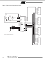
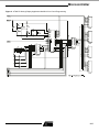
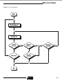
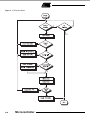
AT89C51 In-Circuit Programming
This application note illustrates the in-circuit programmability of the Atmel
AT89C51 Flash-based microcontroller.
Guidelines for the addition of in-circuit
programmability to AT89C51 applications are presented along with an application example and the modifications to
it required to support in-circuit programming. A method is then shown by which
the AT89C51 microcontroller in the
a pp l i c a ti o n c a n be r e p r og r a m m ed
remotely, over a commercial telephone
line. The circuitry described in this application note supports five volt programming onl y, requi ring the use of an
AT89C51-XX-5. The standard AT89C51
requires 12 volts for programming.
The software for this application may be
obtained by downloading from Atmel’s
BBS: (408) 436-4309.
General Considerations
Circuitry added to support AT89C51 incircuit programming should appear
transparent to the application when programming is not taking place.
EA/VPP must be held high during programming. In applications which do not
utilize external program memory, this pin
may be permanently strapped to V CC .
Applications utilizing external program
memory require that this pin be held low
during normal operation.
RST must be held active during programming. A means must be provided
for overriding the application reset circuit, which typically asserts RST only
briefly after power is applied.
PSEN must be held low during programming, but must not be driven during normal operation.
ALE/PROG is pulsed low during programming, but must not be driven during
normal operation.
During programming, AT89C51 I/O ports
are used for the application of mode
select, addresses and data, possibly
requiring that the controller be isolated
from the application circuitry. How this is
done is application dependent and will
be addressed here only in general
terms.
Port Used for Input
During programming, the controller must
be isolated from signals sourced by the
application circuitry. A buffer with threestate outputs might be inserted between
the application circuitry and the controller, with the buffer outputs three-stated
when programming is enabled. Alternately, a multiplexer might be used to
select between signal sources, with signals applied to the controller by either
the application circuitry or the programmer circuitry.
8-Bit
Microcontroller
with Flash
Application
Note
Port Used for Output
No circuit changes are required if the
application circuitry can tolerate the state
changes which occur at the port during
programming. If the prior state of the
application circuitry must be maintained
during programming, a latch might be
inserted between the controller and the
application circuitry. The latch is enabled
during programming, preserving the
state of the application circuitry.
An Application Example
The AT89C51 application shown in Figure 1 is an implementation of a moving
display. This application was selected for
its simplicity and ability to show graphically the results of in-circuit reprogramming. The text to be displayed is programmed into the controller as part of its
firmware, and cannot be changed without reprogramming the device.
0287D-B–9/97
5-11
The displayed text is presented in one of two modes
selected by the four-position DIP switch. In the first mode,
one character at a time enters the display from the right
and moves quickly to the left through each element of the
display to its final position in the assembled message. In
the second mode, the message moves through the display,
from right to left, with the display acting as a window onto
the message. This mode is familiar as the method often
used in displays of stock prices.
The output consists of four DL1414T, four-digit, 17-segment alphanumeric displays with integral decoders and
drivers. This yields 16 total display elements, each capable
of displaying digits 0-9, the upper case alphabet, and some
punctuation characters. The displayable character codes
are ASCII 20H-5FH.
A power-on reset circuit and a 6-MHz crystal oscillator
complete the application. Neither external program memory
nor external data memory is used.
Modifications to the Application to Support
In-Circuit Programming
Figure 2 shows the application modified for in-circuit
programming.
It is assumed that the programmer, when inactive, will neither drive nor excessively load the application.
Since the application does not use external program memory, EA/VPP on the controller is connected to VCC . This
meets the requirement for programming.
The reset circuit has been modified by the addition of two
transistors, which allow RST on the controller to be forced
high by the programmer.
PSEN and ALE/PROG, unused in the basic application, are
under the direct control of the programmer.
Programming requires programmer access to all of the four
AT89C51 I/O ports, as documented in the data sheet. The
programmer is connected directly to those controller pins
which are unused by the application, while access to pins
used by the application requires special treatment, as
explained in the following paragraphs.
The least significant four bits of the address generated by
the programmer are multiplexed onto port one of the controller with the data from the DIP switch. Note that the four
resistors added at the switch are not required in the basic
application, since the AT89C51 provides internal pull-ups
on port one.
During the normal operation of the application, controller
ports zero and two provide data and control signals
(respectively) to the displays. During programming and program verification, the programmer asserts control of port
zero and part of port two. The programmer is connected to
ports zero and two without buffering, since, when inactive,
its presence does not affect the normal operation of the
application.
5-12
Microcontroller
A transparent latch has been added between port two of
the controller and the display control inputs. The latch holds
the display control signals inactive during programming,
which eliminates erratic operation of the displays due to
programmer activity on ports zero and two. No isolation of
the display data inputs is required, since data applied to the
inputs is ignored when the control signals are inactive.
The AT89C51 reset circuit, input multiplexer and output
latch are controlled by a single signal generated by the programmer. During programming, reset is asserted, the multiplexer switches inputs, and the latch freezes the display
control lines.
To ensure that the display control lines are in a known state
before they are latched, an AT89C51 external interrupt is
used to allow the programmer to signal the application
before asserting reset. The application firmware responds
to the interrupt by displaying a message and deactivating
the display control lines.
After programming, when reset is deasserted, the controller
ports are high as the latch becomes transparent. Since the
display control inputs are inactive high, the display contents
are not disturbed until the new program writes the display.
Although not essential to this application, it might be imperative in some applications that the state of the peripheral
circuitry not be disturbed during programming.
The Programmer
The programmer (Figure 3) generates the addresses, data
and control signals necessary to program the AT89C51
embedded in the application.
The programmer circuitry consists of an AT89C51 and an
RS-232 level translator. The controller runs at 11.0592
MHz, which allows the serial port to operate at a number of
standard baud rates. A Maxim MAX232 line driver/receiver
produces RS-232 levels at the serial interface while requiring only a five volt supply.
Many of the signals generated by the programmer are connected directly, without buffering, to the AT89C51 in the
application. These signals, when inactive, are not threestated, but are pulled high. The AT89C51 has internal pullups of approximately three Kohms on ports one, two and
three. Because port zero does not have internal pull-ups,
external pull-ups of ten Kohms have been added to permit
proper operation of program verification mode. The sample
application operates correctly in this environment. If
required for compatibility with an application, programmer
signals may be buffered with three-state buffers similar to
the 74xx125.
The AT89C51 in the programmer does not utilize external
program or data memory, which would require sacrificing
needed I/O pins. This requires that program code and I/O
buffers be kept small enough to fit in on-chip memory.
Microcontroller
Remote Programming Over a Commercial
Telephone Line
The programmer and display application described previously are connected to a phone line via a modem at a
remote site. Using a personal computer with a modem, a
user can upload a new program containing a new message, which is programmed into the AT89C51 embedded in
the application. When programming is complete, the application executes the new program, which displays the new
message.
Local Station
The local station in the test configuration consists of an IBM
PC AT-class computer connected to a Hayes-compatible,
Prometheus 1200 baud modem. The modem was selected
because it was inexpensive and available. A faster modem
may be used if desired, although once the file transmission
time is reduced below one minute, further reductions in
transmission time do not further reduce connect time
charges. A possible advantage to higher transmission
speeds is the automatic error detection and correction
available in some high speed modems.
Procomm Plus version 2.01, a commercial data communications package, is used to configure the modem, set up
communications parameters, and establish a link with the
remote modem. Procomm Plus includes a macro language
called ASPECT, which allows the user to write and compile
scripts which implement custom file transfer protocols. A
simple ASPECT script was written to read the contents of a
program file and upload it to the remote programmer.
The file transfer protocol (FTP) implemented is a simple
send-and-wait, packet-oriented protocol. The transmit and
receive modes of the FTP are illustrated by the flowcharts
in figures 4 and 5, respectively. The transmitter sends each
packet without flow control and waits for a response. The
programmer (the receiver) reads and dissects the packet
while calculating a checksum. If the calculated checksum is
valid, the programmer acknowledges the packet by sending an ACK. If the checksum is in error, the programmer
negatively acknowledges the packet by sending a NAK.
Upon receipt of an ACK, the transmitter sends the next
packet. If the transmitter receives a NAK, it resends the
same packet. Transmission proceeds in this manner until
the entire file has been transferred.
The programmer might respond to a packet by sending a
CAN, which indicates that a non-recoverable error has
occurred and that the transmitter should immediately abort
the file transfer. If the programmer fails to respond to a
packet within a limited period of time, the transmitter will
resend the same packet. The transmitter will continue to
resend the same packet until a valid response is received
or until the allowed number of attempts is exceeded, at
which time the file transfer is aborted.
After each packet is received and validated by the programmer, the data contained in the packet is programmed
into the AT89C51 controller in the application. After programming, the data is read back from the controller and
verified against the received packet data. Successful verification indicates successful programming, causing the programmer to send ACK to the transmitter. If programming
fails, the programmer sends CAN to signal the transmitter
to abort the file transfer.
The simplicity of the FTP reduces the amount of AT89C51
program memory used in the programmer. The send-andwait nature of the FTP allows inter-packet delays due to
AT89C51 program and erase times to be easily absorbed.
Support for program verification is transparent, requiring no
explicit command or result codes, or additional data transfers.
The files which are uploaded to the programmer are created with the tools in the Intel MCS-51 Software Development Package for the IBM PC. Included in the package are
the MCS-51 Macro Assembler, MCS-51 Relocator and
Linker, and a useful utility, OH. OH converts an absolute
8051 object file to an equivalent ASCII hexadecimal object
file.
The records in the hex file produced by the OH utility serve,
unchanged, as the packets in the FTP described above; no
service fields need to be added. The colon which begins
each record serves as the packet signature field. The load
address field serves as the packet sequence number. A
checksum is provided as the last field in each record. Since
seven-bit ASCII coding is utilized, the eighth bit of each
byte is available to be used for parity checking.
Because the AT89C51 in the programmer does not utilize
external data memory, necessary packet buffering must be
done using internal RAM. Limited memory precludes the
use of conventional FTPs which utilize packets of 128
bytes and larger. The hex packet format used in this application limits packet data fields to 16 or fewer entries, requiring little memory for buffering.
The ready availability of a utility for creating the packetized
program file, combined with small packet size and adequate error checking, makes the hex packet format a near
ideal solution for this application. A disadvantage is the use
of ASCII, which requires each program data byte to be
expressed as two hex characters. This demands that
nearly twice as many bytes be transferred as might otherwise be required. This is not a severe limitation, however,
since typical file transfer times are less than one minute.
Overall, the simplicity of the custom FTP/hex packet format
implementation outweighs the drawbacks.
Remote Station
The remote station in the test configuration consists of the
display application and programmer circuits, described previously, connected to a Hayes-compatible, Prometheus
5-13
1200 baud modem. During normal operation, the application executes its internal program while the modem and
programmer monitor the phone line for incoming calls.
After a call has been detected and a connection established, the programmer forces the application to suspend
execution of its program. The new program is then downloaded and programmed into the AT89C51 embedded in
the application. When programming is complete, the application is allowed to begin execution of its new program,
and the programmer returns to monitoring the phone line
for the next call.
The programmer powers up with its programming control
outputs inactive, allowing the application to run normally.
After configuring the modem to answer incoming calls, the
programmer puts itself to sleep. The programmer will not
disturb the application until a new program is to be downloaded.
The programmer controls the modem by sending ASCII
command strings over the serial interface, to which the
modem responds with Hayes-style ASCII numeric codes.
The software is designed for use with Hayes-compatible
modems, which includes the Prometheus ProModem 1200
used here.
The serial interface, through which the programmer connects to the modem, supports two handshaking signals,
DTR and DSR. On power up, the programmer asserts
DTR, to which the modem responds by asserting DSR. If
the modem should fail to respond to any command, including the command to hang up, the programmer deasserts
DTR, which forces the modem to drop the line.
The modem monitors the phone line while the programmer
sleeps, waiting for an incoming call. When a call is
detected, the modem answers and attempts to establish
communication with the caller. If a connection is established, the modem sends a code to the programmer, waking it up. The programmer verifies the connect code and
begins polling for a valid packet header.
Incoming packets must arrive fewer than thirty seconds
apart, or the modem drops the line (hangs up) and the programmer returns to sleep, waiting for the next call. If the
caller hangs up, the thirty second period must expire before
another call will be answered. Calls incoming during the
reset delay period are ignored.
If a valid packet header is received prior to the expiration of
the reset delay period, the programmer will attempt to read
and validate the incoming packet. At any time during
packet reception, an invalid character, parity error or timeout during character reception will cause the partial packet
to be declared invalid and discarded.
Two packet types are defined: data and end-of-file. A data
packet contains five fields in addition to the packet header,
one of which is a variable length data field. The data field
contains program data to be written into the AT89C51 con5-14
Microcontroller
troller in the application. The load address field contains the
address at which the data is to be written. The end-of-file
packet contains the same fields as the data packet, except
that the data field is empty. This packet type has special
meaning to the programmer, as explained below.
Any packet which contains an invalid record type, record
length or checksum is invalid. Program data accumulated
during the processing of an invalid packet is discarded. The
programmer sends a NAK to the transmitter to signal
reception of an invalid packet and resumes polling for a
valid packet header.
Receipt of the first valid data packet causes the programmer to interrupt the application controller. The controller
responds to the interrupt by abandoning execution of its
usual program and displaying a message indicating that
programming is taking place. If this is the first valid data
packet since power was applied or an end-of-file packet
was received, the programmer asserts the control signals
necessary to erase the program memory in the application
controller. The programmer then places the controller in
programming mode.
The first and subsequent valid data packets are dissected
as they are received and the data which they contain is programmed into the application controller at the address indicated in the packet load address field. After programming,
the data is read back from the controller and verified
against the received packet data. Successful verification
indicates that programming was successful, causing the
programmer to send ACK to the transmitter. The programmer then resumes polling for a valid packet header, subject
to the thirty second reset delay.
If programming fails, the programmer sends CAN to signal
the transmitter to abort the file transfer. The modem drops
the line and the programmer returns to sleep, waiting for
the next call. The application controller is left in programming mode, preventing it from executing the incomplete or
invalid program which it contains.
It is important to note that invalid packets are NEVER programmed into the application controller. To do so would
require that the program memory in the controller be completely erased before the error could be corrected, causing
the non-recoverable loss of all previous program data.
Upon receipt of an end-of-file packet, the programmer
returns its control outputs to the inactive, power on state,
allowing the application controller to begin execution of the
new program. The programmer then resumes polling for a
valid packet header, subject to the thirty second reset
delay.
If a valid packet is received prior to the expiration of the
thirty second delay, another programming cycle begins,
which can only be terminated by the reception of a valid
end-of-file packet.
Microcontroller
If the reset delay expires prior to the reception of a valid
end-of-file packet, the modem will drop the line and the programmer will return to sleep, waiting for the next call. In this
case, the application controller is left in programming
mode, preventing it from executing its program. To return
the application to normal operation, another call must be
received, and a valid program file uploaded, terminated by
an end-of-file packet.
Setting Up the Hardware
Local Station
Connect the IBM PC to the ProModem 1200 through one of
the system COM ports. Connect the modem to an analog
telephone line and set the modem switches as indicated
below.
Switch settings:
1
2
3
4
5
6
7
8
9
10
ON
ON
OFF
ON
OFF
ON
OFF
OFF
OFF
OFF
Remote Station
Connect the display application/programmer to the second
ProModem 1200 through the programmer serial port. Connect the modem to an analog telephone line and set the
modem switches as indicated below.
Turn the modem on and apply power to the display application/programmer. The application will begin executing its
program, if it contains one. The programmer will initialize
the modem, as shown by the activity on the modem status
indicators.
Switch settings:
1
2
3
4
5
6
7
8
9
10
ON
ON
ON
OFF
ON
ON
ON
OFF
OFF
OFF
Installing and Configuring Procomm Plus,
Version 2.01
Install Procomm Plus as instructed in the User Manual.
When prompted to specify the modem in use, select
‘Prometheus ProModem 1200’ from the list.
Run Procomm Plus and create a dialing directory entry for
the remote station. The baud rate must be set to 1200, parity to EVEN, number of data bits to 7, number of stop bits to
1, plex to HALF.
Enter the Setup utility (ALT-S). Select ’PROTOCOL
OPTIONS’, then ’EXTERNAL PROTOCOL OPTIONS’ from
the menus and modify the entry for ’EXTERNAL PROTOCOL 1’ as indicated below.
EXTERNAL PROTOCOL 1:
A - NAME:
<any name>
B - TYPE:
ASPECT
C - UPLOAD COMMAND:
ATX.ASX
Note:
’ATX.ASX.’ is the filename of the compiled ASPECT
script to be associated with External Protocol 1.
Save the changes and exit the Setup utility.
Creating a Hex File
The hex files which are uploaded to the programmer are
created with the tools in the Intel MCS-51 Software Development Package for the IBM PC. In the example below, the
8051 assembler source file is called ’TEST.ASM’.
Assemble the source file ’TEST.ASM’ and create the object
file ’TEST.OBJ’:
ASM51 TEST.ASM
Link and locate the object file ’TEST.OBJ’ and create the
absolute object file ’TEST.ABS’:
RL51 TEST.OBJ TO TEST.ABS
Convert the absolute object file ’TEST.ABS’ to the hex file
’TEST.HEX’:
OH TEST.ABS TO TEST.HEX
The resulting file, ’TEST.HEX’ is ready to be uploaded.
Note:
ASM51 is version 2.3; RL51 is version 3.1; OH is version
1.1.
Uploading a Hex File
Run Procomm Plus and use the proper dialing directory
entry to dial the remote station.
After the connection with the remote station is established,
press the ’PgUp’ key and select ’1’ (External Protocol 1)
from the menu of upload protocols. This will execute the
ASPECT script associated with External Protocol 1.
When prompted, enter the name of the file to be uploaded,
including the extension and path, if required.
When the upload is complete, press ALT-H to hang up and
ALT-X to exit Procomm Plus and return to DOS.
5-15
Figure 1. AT89C51 Moving Display Application Example
U2
VCC
8
9
10
11
2
1
12
D0
D1
D2
D3
D4
D5
D6
5
4
A0
A1
3
+ C1
10 uF
DL1414T
U1
C2
R1
8.2 K
WR
31
30 pF
Y1
6 MHz
19
P0.0
P0.1
P0.2
P0.3
P0.4
P0.5
P0.6
P0.7
EA/VPP
XTAL1
C3
18
30 pF
9
10
11
12
13
14
15
S1
1
2
3
4
8
7
6
5
SW DIP-4
1
2
3
4
5
6
7
8
XTAL2
RST
P2.0
P2.1
P2.2
P2.3
P2.4
P2.5
P2.6
P2.7
P3.0/RXD
P3.1/TXD
P3.2/INT0
P3.3/INT1
P3.4/T0
P3.5/T1
P1.0
P1.1
P1.2
P1.3
P1.4
P1.5
P1.6
P1.7
39
38
37
36
35
34
33
32
21
22
23
24
25
26
27
28
U3
8
9
10
11
2
1
12
D0
D1
D2
D3
D4
D5
D6
5
4
A0
A1
3
WR
DL1414T
U4
PSEN
ALE/PROG
29
30
P3.6/WR
P3.7/RD
16
17
AT89C51
8
9
10
11
2
1
12
D0
D1
D2
D3
D4
D5
D6
5
4
A0
A1
3
Note: 0.1 uF bypass caps on all ICs.
WR
DL1414T
U5
8
9
10
11
2
1
12
D0
D1
D2
D3
D4
D5
D6
5
4
A0
A1
3
WR
DL1414T
5-16
Microcontroller
Microcontroller
Figure 2. AT89C51 Moving Display Application Modified for In-Circuit Programming
5-17
Figure 3. AT89C51 Programmer
5-18
Microcontroller
Microcontroller
Figure 4. FTP Transmit Mode
5-19
Figure 5. FTP Receive Mode
5-20
Microcontroller
Microcontroller
Appendix I: Intel Hex File Definition
Hexadecimal object file format (Intel hex) is produced by
most 80C51 assembler products.
Each record in the file contains the following fields:
<:><rec length><load address><rec type><data><checksum>
The colon is the record header.
The record length field consists of two hex digits, and represents the number of entries in the data field. OH outputs
records containing 16 or fewer data field entries.
The load address field consists of four hex digits, and indicates the absolute address at which the data in the data
field is to be loaded.
The record type field consists of two hex digits, which are
always zero in data records.
The data field contains from one to 16 pairs of hex digits.
The last two hex digits are a checksum on the record
length, load address, record type, and data fields. The sum
of the binary equivalents of these fields and the checksum
itself is zero.
Each record in the file is terminated by a carriage return
and line feed.
A type one record marks the end of the file. The record
always contains the following value: ’:00000001FF’.
5-21