1
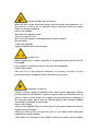
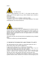
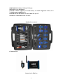
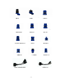
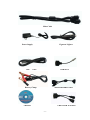
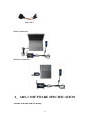
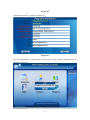
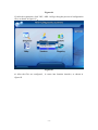
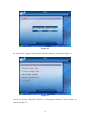
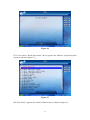
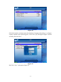
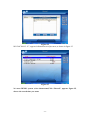
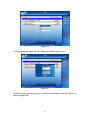
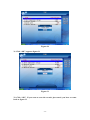
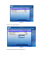
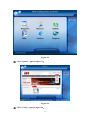
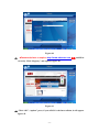
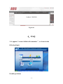
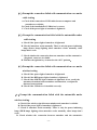
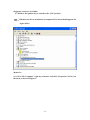
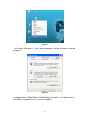
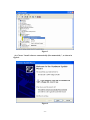
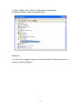
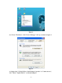
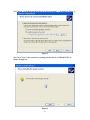
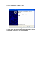
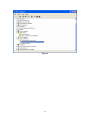
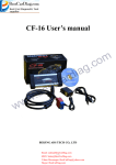
ADS-1 USER'S MANUAL
BEIJING TIANYUAN-TECH CO,.LTD
http://www.adsscan.com
-1-
OPERATING
INSTRUCTION
Dear Customers:
The tool you have chosen is part of the ADS-1® range of products, it covers
the whole technology our staff has acquired in its years long experience. It will be
a useful working tool to satisfy both you and your customers.
ADS-1®is glad to include you among its Customers; In addition, thanks to wide
our range of products. we are confident we will satisfy your current and future
needs.
Our authorized dealers and "Customer service" will solve any technical
problem for you completely.
-2-
CATALOG
1.BRIEF-INTRODUCTION ................................. - 4 2.ADS-1 SOFTWARE SPECIFICATION ......... - 12 3.GET PASSWORD ILLUSTRATION ............. - 35 4.FAQ .................................................................... - 38 -
-3-
1.BRIEF-INTRODUCTION
This manual is an undivided part of the product. It describes technical
features and functions. Please read these instructions carefully before using the
tool and store them for future needs.
ADS-TECH apologizes for any errors in the text.
Brand names and products mentioned in the document are registered brands
of the relevant owners.
In any case will ADS-TECH be responsible to third parties for specific,
collateral, accidental, direct and indirect damages related to or deriving from the
product purchase and use. Requests for copies of this document or technical
information have to be submitted to an authorized reseller or a sales agent of
ADS-TECH.
This publication cannot be copied or distributed, partially or entirely, under
any form or mean, without previous written authorization by Beijing ADS-Tech
Co., Ltd.
1.1 IMPORTANT INFORMATION ABOUT PERSONAL SAFETY
GENERAL SAFETY AND BEHAVIOUR
WORKSHOPS OR SIMILAR PLACES.
PRESCRIPTIONS
FOR
ACTIVITY
IN
DANGER OF SUFFOCATION
GASOLINE ENGINES
Exhaust gases from gasoline vehicles contain Carbon Monoxide, a colorless and
odourless gas that, in case of inhalation, can cause serious physical injury or
death. When working inside pits, should be very cautious. Because some
components of exhaust gas are heavier than air and fall to the pit bottom.
SAFETY MEASURES:
-Always ensure good ventilation and breathing protection (especially in
-4-
inspection pits).
- Always operate the exhaust fan system when working in closed rooms.
DANGER OF CRUSHING
You may be crushed against the work bench if the vehicle has not been correctly
locked in place by mechanical systems.
SAFETY MEASURES:
-Make sure that the vehicle is unable to move by engaging the hand brake and
locking the wheels.
DANGER OF INJURY
Whether engines are at a standstill or operating, there are moving parts (belts,
etc.) that can injure hands and arms.
Amongst various engine components, machines, you should pay particular
attention to their electronic fans since they may unexpectedly start-up even when
the engine itself is off.
SAFETY MEASURES:
-When working near the electronic fan, firstly, let the engine cool, and then
unplug the fan.
-Keep the tester connection wires as far as possible away from moving parts of
the engine.
DANGER OF BURNS
Some of the components in engines (exhaust gas manifold, etc.) can become very
hot, which need to configure corresponding sensors.
Never touch these parts.
SAFETY MEASURES:
-Wear protective gloves.
-Never drape the test instrument connection wires over or near hot parts.
-Never keep the engine running after the tests
-5-
DANGER OF FIRE OR EXPLOSION
When the fuel system works(fuel pump, injection nozzle and carburetor, etc.)
there may be a risk of fire or explosion owing to the fuels and/or the vapors
which are wrongly composed.
SAFETY MEASURES:
-Disconnect the ignition system
-Allow the engine to cool.
-Do not use open flames or anything liable to produce sparks.
-Do not smoke.
-Collect any spilt fuel.
-Operate exhaust fans in closed rooms
SOUND LEVEL
When working near a vehicle, especially at a high engine speed, noise levels can
reach 90dB.
Long exposure to such noise sources can cause hearing damage.
SAFETY MEASURES:
-The user has to take protective measures, if necessary, you have to wear
personal protective equipment at the work place near test area.
DANGEROUS VOLTAGE
Voltage is always a danger, including all the vehicle electric apparatus. When a
person touches test instruments or parts of engines which are electrified, there is
always a risk of electric shock, for example, get electrocuted due to damage of
the connection point. This is true for both the primary and secondary ignition
system and test instrument connections.
SAFETY MEASURES:
-Only use the supplied cables to connect the test instrument. Make sure that the
insulation is not damaged.
-Make sure that you do not touch live parts of the vehicle when testing and
regulating the engine running.
-Only make test connections with suitable systems (test cables, specific adapter
-6-
cables).
DANGER OF TUBE
If suffering high temperature (over 250 °C or fire alarm), the tubes used to
exhaust gas will release highly toxic gas, which, if inhaled, may be harmful to
your health.
SAFETY MEASURES:
-use neoprene or PVC gloves to eliminate combustion residue.
-Combustion residue can be neutralized with calcium hyduloxide. The formed
calcium fluoride can be removed with water.
DANGER OF CORROSION
The condensate that remains in the gas sampling pipe and condensate separator
contains acid. Pay close attention when the oxygen sensor and the CO Sensor are
replaced, since they contain highly corrosive substance. Corrosive liquid maybe
spill if the liquid crystal indicator is broken. This liquid should never be touched,
inhaled or swallowed.
SAFETY MEASURES:
-If it sticks to the skin, rinse the hands with water immediately and go to hospital
timely.
-If inhaled or swallowed, go to hospital immediately.
1.2 IMPORTANT INFORMATION ABOUT PRODUCT SAFETY
This ADS-1product provides a high level of protection against the risk of
electric shock. It has a class -II power supply device.
Comply with the following rules to avoid the risk of electrocution:
-Connect the instrument to power socket under suitable voltage. If you are
uncertain of the voltage, please contact the power company.
-If there are other wires besides the power cable, they must be connected to their
respective connectors before connecting the power cable to electrical outlet.
-Disconnect the power cable from the socket before removing other wires.
-Never open the cover of DEVICE. This operation can only be carried out by
qualified technicians and be finished in the condition of disconnecting the power
-7-
cable.
- Deviating from the instructions in this manual or attempting to repair the
Device is
dangerous.
-Things too hard pressed on the display may damage the Device.
-Contact a service technician if the DEVICE fails to correctly function after
following the operating instructions.
-Check that all installed spare parts have technical characteristics identical to
those of the original parts. Other parts may not possess the same safety
characteristics.
Always contact qualified technical personnel if repairs are required.
1.3 HARDWARE INFORMATION
INSTALLATION
Never allow the DEVICE to be exposed to the sun for a long period or allow
it to stand near hot equipments (stoves, heaters, etc.): the maximum operating
temperature is 40 °C/ 105 F.
OPERATING INFORMATION
To prevent contamination from toxic gas, it is advisable to use the instrument
in a sufficiently ventilated place or to channel exhaust gases outdoors.Never pull
on the instrument's cables. All connections should be made when the vehicle
engine is off. Check that all cables are far away from hot places (over 50 °C/ 130F)
or moving parts. Disconnect all engine connections before moving the vehicle.
WHEN NOT TO USE THE INSTRUMENT
If DEVICE is not to be used for a long time, place it in its original case.
CLEANING
When necessary, the outer surfaces of DEVICE should be cleaned: never use
cleaning products containing spirits, ammonia or gasoline. Only use neutral
detergents and soft, slightly moistened cloth.
The ADS-1 is a digital portable tool, compact and user's friendly
characterized by state-of-the-art technology that allows diagnostics on all types
of communication protocols of automotive. The tool is sold inside a packing case
that, besides containing the cables necessary for the connections to the vehicles,
allows to protect the tool and its accessories before and after the use.
SPECIFICATIONS
-8-
DIMENSIONS: 125mm X 98mm X 39mm
WEIGTH: 3.5~4.5kgapprox.
POWER SUPPLY: typically 12 V from battery or vehicle diagnostics socket, or 12
V with its power supply device.
POWER CONSUMPTION: no more than 2W @ 12 V
WORKING TEMPERATURE: 10+40°C
Standard Accessories
Connector List
Smart box & Min box
-9-
BENZ
BMW
CRYSLER-6
JEELY-17
TOYOTA/MAZDA-17
GM-12
OBDII-16
CANBUS
FLAT & DAIHATSU
NISSAN
KIA-20
HONDA-3
TOYOTA-17
AUDI-2+2
- 10 -
Main Cable
Power Supply
USB
Cigarette Lighter
Cable
CITROEN-2
Battery Clamp
MITSUBISH &HYUNDAI
CD-ROM
CHINA STAR & SUZUKI
- 11 -
Universal-3
Wired Connection
Wireless Connection
2.ADS-1 SOFTWARE SPECIFICATION
1.Double click ADS-1(EN) on desktop
- 12 -
Figure-01
2.If it is the first time to start up ADS-1 (EN) program,you must regist to use the
software.Before registry,you have to connect smart box with personal compute
and power on. Double click “Registry”, it will ask you to fill in detailed
information as figure-02. Red parts are required.
Attention: Rand code is different every time, you have to get Password through
the internet(http://www.adsscan.com/english) (reference to “How to get
Password ”)
- 13 -
Figure-02
3. Register correctly, as shown in figure-03。
Figure-03
4. If the registration is correct, there will emerge "login succeed" message box, as
shown in figure-04。
- 14 -
Figure-04
5. After the registration, click "OK", ADS-1 will go along the process of configuration
files, as shown in figure-05.。
Figure-05
6. After the files are configured , it comes into function interface, as shown in
figure-05.
- 15 -
Figure-06
F7. Click “Diagnose”, it appears the interface of regional selection, as shown in
figure-07
- 16 -
Figure-07
8. Click “China” comes into the Chinese regional interface, as shown in figure-08
Figure-08
9. Take “DEMO” for an example, click “DEMO”, appears figure-09
Figure-09
10. Click “DEMO”, appears a hint to choose connector, as shown in figure-10
- 17 -
Figure-10
11. Click "OK", appears the functional selection interface, as shown in figure-11
Figure-11
12. If you choose “Read Ecu Version”, it will appear content of Ecu Version. As
shown in figure-12
- 18 -
Figure-12
13. If you choose “Read trouble code”, it will appear content of trouble code, as
shown in figure-13
Figure-13
14. If you choose “Clear trouble code”, it will appear an interface whether to clean out
DTC, as shown in figure-14.
- 19 -
Figure-14
15. If you choose “Cancel”, then it comes back to the functional selection interface, as
shown in figure-10, or if you choose “OK”, it will appear figure-15.
Figure-15
16. If you choose “Cancel”, then it comes back to the functional selection interface, as
shown in figure-10;or if you choose “OK”, it will appear figure-16
- 20 -
Figure-16
17. If you choose “Read data stream” then it appears the interface of choosing data
stream, as shown in figure-17.。
Figure-17
18. Click "Back", appears the content of data stream, as shown in figure-18
- 21 -
Figure-18
19. In this interface, the data stream has functions of storing and printing. we will give
separate explains in the following parts. Click “Save [F2]”and appears figure-18,fill in
carefully and click“Save”
Figure-19
20. Click “Save”, and appears figure-20
- 22 -
Figure-20
21. Click “OK, appears figure-21
Figure-21
22. Click “OK” to finish the data saving, then click “Back” to come back to figure-22
- 23 -
Figure-22
23. Click “Record”, appears the saved information, as shown in figure-23
Figure-23
24. Click”Jing-88888888”, pops up figure-23
- 24 -
Figure-24
25. Click”2009-5-15”, appears information saved just now, as shown in figure-25
Figure-25
26. enter DEMO system ,select datastream,Click “Record”, appears figure-25,
choose the record time you want.
- 25 -
Figure-26
27. Then it appears figure-26, after filling in carefully, click "Save".
Figure-27
28. Then it pops up a message box to remind you whether to save the records, as
shown in figure-28.
- 26 -
Figure-28
29. Click “OK”, appears the interface which is storing information, as shown in
figure-29。
Figure-29
30. After memorizing the data, appears figure-30
- 27 -
Figure-30
31. Click “OK”, appears figure-31
Figure-31
32. Click “OK”. If you want to scan the records just stored, you have to come
back to figure-32
- 28 -
Figure-32
33. Click “Record”, and double click“JING-88888888” as shown in figure-33
Figure-33
34. Double click 2009-5-15, appears figure-34.
- 29 -
Figure-34
35. Click “Play”, appears figure-35.
Figure-35
36. Choose the interval time, as shown in figure-36
- 30 -
Figure-36
37. After broadcasting the record data, appears figure-36, means the
broadcasting has finished
Figure-37
38. Come back to figure-38
- 31 -
Figure-38
39. Click “Update”, appears figure-39。
Figure-39
40. Click “CarUp”, appears figure-40。
- 32 -
Figure-40
41. “Password”have to explore http://www.adsscan.com 获得 and fill in
correctly. Click “Registry” and appears figure-40.
Figure-41
42. Click “OK”, “update” press, if your ADS-1 is the latest edition, it will appear
figure-42.
- 33 -
If the so Figure-42
43. If your ADS-1 is not the latest, it will appear figure-43
Figure-43
44. After download, ADS-1 will reset automatically
- 34 -
3.GET PASSWORD ILLUSTRATION
Step1: Open up IE, explore http://www.adsscan.com/english
as shown in
Figure-01
Figure-01
Step2: If you haven't registered, please register first. Click “Register” and
appears Figure-02. Fill in carefully。
Figure-02
Step3: Press button“Continue”, after your registration, appears
figure-03
- 35 -
Figure-03
Step4: After your registration, please input your user name and password, as
shown in figure-04。
Figure-04
Step5:Press button “Login”, emerges figure05
Figure-05
Step6: Click “Get Password”, appears figure6. Fill in “Product code” and “Rand
code” according to ADS-1“Registry Information” in figure-06.。
- 36 -
Step6: Press button “Get password”, then get “password”, as shown in figure-06.
Figure-06
Step7: Press button “Get password”, then get “password”, as shown in figure-07
- 37 -
Figure-06
4.FAQ
1. It appears "connect failed with commbox " , as shown in the
following figure.
Possible problems
- 38 -
(1.)Prompt the connection failed with communication case under
cable testing
A. Check if the connection of USB cables between computer and
smartbox are reliable。
B. Check if the installation of USB driver is correct
C. Check if the power light of smartbox is lightened
(2.)Prompt the communication failed with the automobile under
cable testing
A. Check if the power light of smartbox is lightened
B. Check if smartbox works normally. There is only the power indicating
lamp (Power lamp) lighting when smartbox works normally, other
lamps don’t work.
C. Check whether the connection between smartbox and the automotive
diagnostic connector is reliable
D. Whether the ignition key is turned to the “ON” position。
(3.)Prompt the connection failed with communication case under
wireless testing
A. Check if the power light of smartbox is lightened.
B. Check if the RED power light of minbox is lightened.
C. Check if the GREEN light of minbox is lightened; if not, rectify the
antenna orientation between minbox and smartbox, or adjust the
distance between them.
D. Check if the USB driver is installed correctly.
(4.)Prompt the communication failed with the automobile under
wireless testing.
A. Check if the wireless signal between minbox and smartbox is reliable.
B. Check if the power light of smartbox is lightened.
C. Check if smartbox works normally. There is only the power indicating
lamp (PWR lamp) lighting when smartbox works normally, other lamps don’t
work.
D. Check whether the connection between smartbox and the automotive
- 39 -
diagnostic connector is reliable.
E. Whether the ignition key is turned to the “ON” position.
(5). Whether the driver installation is completed, If it has,it should appear the
figure below
Method 1:
(1). Click "My Computer" right key of mouse, and click "Properties" left key on
the desk, as shown in figure 1.
- 40 -
Figure 1
(2). Choose "Hardware" , click "Device Manager" left key of mouse, as shown
in figure 2.
Figure 2
(3). Right-click "CP2102 USB to UART Bridge Controller" of "Other devices",
and choose "Update Driver", as shown in figure3.
- 41 -
Figure 3
(4). Choose "install software automatically (Recommended) ", as shown in
figure4.
Figure 4
- 42 -
(5) .The system is searching for the driver of CP2102 USB, as shown in figure 5.
Figure 5
(6). Finish the installation, as shown in figure6.
Figure 6
- 43 -
(7) Click "Finish", there will be "CP2101 USB to UART Bridge
Controller(COM4)" in the Ports(COM & LPT).
Method 2:
(1). Click "My Computer" right key of mouse, and click "Properties" left key on
the desk, as shown in figure 1.
- 44 -
Figure 1
(2). Choose "Hardware", click "Device Manager" left key, as shown in figure 2.
Figure 2
(3). Right-click "CP2102 USB to UART Bridge Controller" of "Other devices",
and choose "Update Driver", as shown in figure3.
- 45 -
Figure 3
(4). Choose "install software automatically (Recommended) ", as shown in
figure4.
Figure 4
- 46 -
(5). Choose "Search for the best driver in these locations ", as shown in figure 5.
Figure 5
(6). Click "Next", the system is searching for the driver of CP2102 USB, as
shown in figure 6.
Figure 6
- 47 -
(7). Finish the installation, as shown in figure7.
Figure 7
(8) Click "Finish", there will be "CP2101 USB to UART Bridge Controller
(COM4)"in the Ports (COM & LPT),as shown in figure8.
- 48 -
Figure 8
- 49 -