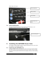
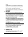
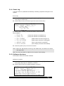
1
Avolites Ltd
ART2000 Power Cube
User Manual
Related to software versions
Main:24 Sept 2009
PDE: 23 Sept 2009
This manual and the products it describes are intellectual property of Avolites
Ltd. England
PowerCubeUser-V1 28/09/2009 16:52:00
Useful Avolites phone numbers:Avolites England
Sales and service*
(+44) (0) 20 8965 8522
Service out of hours*(+44) (0) 831 17 8888
Fax
(+44) (0) 20 8965 0290
Email
[email protected]
Website
http://www.avolites.com
Distribution of Avolites products in USA:Avolites America
Sales and service*
(+1) 423 938 2057
Fax
(+1) 423 938 2059
*Before contacting Avolites for service enquiry please ensure that you have the
product serial number and the Software version (shown at switch on).
The latest version of this manual (MS Word 2000 & PDF) and ART2000 Power
Cube Software can be downloaded from the Internet.
The small print :
No Liability for Consequential Damages
Avolites has a policy of continuous product and documentation improvement. As such the detail
within this manual may not match the operation of the ART2000-PC.
In no event shall Avolites be liable for any direct, indirect, special, incidental, or consequential
damages or loss whatsoever (including, without limitation, damages for loss of profits, business
interruption, or other pecuniary loss) arising out of the use or inability to use the ART2000-PC
even if Avolites Ltd. has been advised of the possibility of such damages. Because some
jurisdictions do not allow the exclusion or limitation of liability for consequential or incidental
damages, the above limitation may not apply to you.
Reprint and revision history:
Created from specification doc By J.B.Toby, Avolites Ltd
General text originally by by Tim Mitchell, Sabre Technology Ltd Tel: 01482 831031
24/09/09 adjusted general text J.B.Toby, Avolites Ltd
PowerCubeUser-V1 28/09/2009 16:52:00
C O N T E N T S
THE ART2000 POWER CUBE DIMMING SYSTEM
5
1.1
What it does
1.2
Important safety information
1.3
Quick start instructions
2. FEATURES OF THE ART2000 POWER CUBE
5
5
5
6
2.1
Flight case lids
2.2
Front
2.3
Back
2.4
Earth bonding pillar
3. INSTALLING THE ART2000 POWER CUBE
7
7
7
8
8
3.1
Positioning the ART2000 rack
3.2
Power supply
3.3
Connections to lights
3.4
Control connection
3.5
Testing channels using the local control faders
3.6
Support from your reseller or Avolites direct
4. THE USER INTERFACE
8
9
9
11
11
11
12
5.
MAIN FUNCTION LIST
12
6.
DMX START ADDRESS IN “START” MODE
14
7.
DMX START ADDRESS IN “PATCH” MODE
14
8.
ARTNET START ADDRESS IN “START” MODE
15
9.
ARTNET START ADDRESS IN “PATCH” MODE
16
10. DMX ADDRESS MODE
16
11. CURVE MENU
18
12. LIMIT MENU
19
13. PRE-HEAT MENU
20
14. MEMORY STORE
21
15. FADERS MODE
22
16. MEMORY REPLAY
23
17. CHANNEL TEST
23
18. LEVELS
23
19. IP SETTINGS, IP, IP MASK AND GATEWAY
24
20. USER SETTINGS
24
20.1
Date & Time
20.2
Panel Lock
20.3
PHASE SETUP
21. SYSTEM
24
25
26
28
21.1
Event Log
PowerCubeUser-V1 28/09/2009 16:52:00
29
21.2
Software Versions
21.3
Serial , MAC, & RDM ID’s
21.4
System Status
21.5
Flicker Finder
22. WIPE ALL
29
30
30
30
31
23. PANEL UNLOCK
31
24. UNLOCK DMX
32
25. SOFTWARE UPGRADE
32
25.1
25.2
25.3
25.4
Future features
System software limitations
Known User Interface issues
PDE-DSP software limitations
PowerCubeUser-V1 28/09/2009 16:52:00
32
32
33
33
The ART2000 Power Cube dimming system
Thank you for selecting the Power Cube.
This manual is designed to help you get the most out of your Avolites
ART2000 Power Cube. Even if you hate reading manuals, read this section
because the next couple of pages contain some important safety
information which you should be aware of.
At the end of the manual there is a quick summary of how the DMX control
system works, a Glossary explaining some of the technical terms used in the
manual, and an Index which can be used to find what you need in the
manual.
1.1
What it does
The ART2000 Power Cube provides a complete solution to Dimming, Moving
Light Power and data distribution. You no longer need to have separate mains
distribution making set-up times faster and reducing the number of individual
components needed to put a show together.
The ART2000 Power Cube controls up to 18 individual dimmer channels with
each a 10A capacity, and can supply up to a further 12 channels of fixed
power, 6 shared channels of 10A and 6 dedicated channels of 10A capacity
There are also two separate 16A utility outlets in the form of two CEE 16A
sockets
The design incorporates full monitoring and status feedback via the backlit
LCD display. For simple events you can operate without a console by setting
up a dimmer state on the test faders, or you can record 12 internal memories
for replaying a simple show.
Other features include DMX and ArtNet input with full DMX patch, dimmer
curve and output limit selection per channel, power OK indicators.
1.2
Important safety information
This system uses 3-phase power and can be a serious hazard to
health. This manual is however not a safety manual.
The system should be installed and operated only by a competent person.
When installing you should check local regulations regarding the separation of
lighting fixtures on different phases. If you are in any doubt as to the safe
installation of the system you should employ the services of a qualified
electrical contractor.
Do not operate the system with known electrical faults or when partially
dismantled because this makes live parts accessible.
Before turning on the ART2000 Power Cube, ensure that mains is correct and
that the three mains LEDs are lit
1.3
Quick start instructions
Below are the step by step quick instructions to safely power up and down a
complete system
1.3.1
Power Up
PowerCubeUser-V1 28/09/2009 16:52:00
è The dimmer should be placed suitable place indoors or outdoors where it
is protected from direct exposure to rain. (see also “Installing the Power
Cube”).Note that the case has markings to indicate what the front side is.
è Remove the Front and Back lid
è Ensure the main breaker is off, and ensure that the channel and utility
breakers are switched off.
è Connect the Power Cube to a 3 phase CEE 63A 5 pin socket delivering 3
phases, Neutral and Earth (TN-S) system.
è Observe that the three mains LEDs on the front are lit.
è Turn on the dimmer by switching on the mains isolator, and observe the
LCD light up and showing the main screen
Note: If you cannot read the display you may need to adjust the display
contrast control at the bottom right hand corner of the display.
è Connect the loads to the dimmer (Socapex, Harting and Cee outlets)
Warning..
Make sure that moving lights are NOT connected to the A12, B1-2 and C1 outlets
è Connect the DMX or Artnet control cables to the dimmer
è Turn on the desired breakers when the load is connected
1.3.2
Power Down
Moving lights;
Note: Be aware that some moving lights prefer to be turned off by sending
them a specific “lamp off” command. This is normally done from the
console.
è “Lamp off” Moving lights
è Turn of the distribution breakers
Dimmer channels;
è Bring down any levels from the console OR…
è remove the DMX feed and press [OK] when the “Locked DMX data
message” appears in the LCD screen this will fade down the channels,
the trip the channel breakers
è Trip the Mains Isolator on the dimmer
Warning: It is preferable not to use the RCB as an ON/OFF switch, as arcing
may reduce the RCB’s protecting ability.
2.
Features of the ART2000 Power Cube
This chapter gives a quick rundown on what each part of the ART2000 Power
Cube does. If you are new to the system, read this!
PowerCubeUser-V1 28/09/2009 16:52:00
2.1
Flight case lids
The front and back flight case lid are identical.
To open the case, press down into the lock as indicated and pull the top of the
lid towards you, then lift it out of the case.
Note: Do not fit the lid while the dimmer is in use. Current regulations
(BS7909) state that the beakers need to be accessible for emergency
use. The controls including the faders can be software locked.
To close the lid hook metal plates on the base of the lid behind the aluminium
case strip as shown and then move the top of the lid towards the dimmer.
And press until the latch secures.
Note: The lids do not fit upside down on the dimmer
2.2
Front
From the top the front panel you will find the large backlit LCD with the menu
controls and local faders. Below that are the dimmed channel breakers and
below that are the distribution breakers.
Lcd
Menu Controls
Dimmed channels
Distribution channels
Utility breakers
Main isolator
2.3
RCB for L1,L2 and L3
Back
The back panel on the top left hand side are the DMX and Artnet in and
outlets, below that are the two utility breakers and to the right are the 8
Socapex or Harting outlets that connect the loads
Below the outlet panel is an area where the mains connector is stored. The
main inlet cable is routed along the perimeter of the flight case as show
below. The edge strip of the flight case provides an edge that retains the
PowerCubeUser-V1 28/09/2009 16:52:00
cable inside the dimmer
DMX and ARTnet
Utility outlets
Load outlets
Stored Mains inlet
cable
2.4
Earth bonding pillar
The Earth Bonding stud which you may need to use depending on your
installation can be found near the main inlet cable
Earth bonding stud
3.
Installing the ART2000 Power Cube
This chapter contains details of how to install the ART2000 Power Cube, either
for temporary or permanent operation.
3.1
Positioning the ART2000 rack
Choose a location for the rack which is as near to the power feed as possible
and allows access to the front and back of the rack. Consider how the cables
will run in from the power feed and out to the lights, and try to avoid crossing
walkways.
PowerCubeUser-V1 28/09/2009 16:52:00
If you are unsure about the safety you should contacts a competent body to
advice you.
The ART2000 Power Cube is designed to operate in a maximum ambient
temperature of 40°C and can run continuously when fully loaded at 10A per
dimmer channel. The rack is fan-cooled, you must ensure there is adequate
ventilation available - if the system is running in a closed room, consider
providing external ventilation to the room (see Specifications on page Error!
Bookmark not defined. for cooling information). The system may shut
dimmer channels down if it cannot release the heat generated.
If you are using the system on an outdoor stage, ensure that the rack is
situated somewhere dry and clear of the ground. If you shelter the rack with
tarpaulins make sure that you do not obstruct the air vents. Black tarpaulin is
generally unsuitable.
3.2
Power supply
The Power Cube can be run from Three phase and Single Phase supplies,
please read the following section carefully
3.2.1
Three Phase power supply
In most cases you need to provide a three phase and neutral power supply to
the ART2000 (TN-S) which is capable of delivering the amount of power
required to run all the lights which are connected to it. If the power supply is
under-rated it may trip during your show if you turn too many lights on at
once. This is obviously not a good thing to happen. Also, an overloaded mains
supply can suffer from a distorted waveform which can make it difficult for
the ART system to control your lights accurately.
Warning: Never use mains supplied with “reduced neutral” cable sizes, as
dimmers inherently dump large currents in the neutral connection.
These kind of mains supplies are sometimes called “industrial” and are
not suitable for dimmer applications.
When ordering or specifying a mains supply state that it is for “phase angle
controlled light dimming”
The frequency of the mains is automatically tracked by the system, which
makes the ART system suitable for use on local generator sets.
3.2.2
Single Phase Power Supply
In some cases you may want to connect the Power Cube to a single Phase
supply. In this case you need to provide a cable that connects the three phase
63A mains inlet to the single phase mains supply. The three phases on the
input of the dimmer are combined to the single phase of the supply.
The single phase supply must not be larger then 63A
When running the Power Cube from Single Phase the dimmer system needs to
be set to run to run of single Phase (see Setting supply
3.3
Connections to lights
You connect the lighting rig to the ART2000 either through the multipin
connectors (Socapex or Harting) or through direct outlets on the rear panel.
There are up to 8 multipin connectors, each of which carries 6 channels
(Harting-type connectors may carry 8 channels).
PowerCubeUser-V1 28/09/2009 16:52:00
Do not connect or disconnect the multipin connectors whilst channels are
turned on, as this may cause arcing which will damage the connectors.
The Power Cube has 3 types of outlet usages, being dedicated Dimmer,
shared dimmer and fixed mains and fixed mains.
The following table shows the outlets and their function
Outlet
Dimmer function
A1
Channel 1 - 6
A2
Channel 1 - 6
B1
Channel 7 - 12
B2
Channel 7 - 12
C1
Channel 13 - 18
Fixed mains function
Capacity
10A
C2
Channel 13 - 18
D1
Channel 19 - 24
D2
Channel 19 - 24
16A
WARNING Take care not to connect the moving
lights to the C1 (Top) outlet by accident. Dimmed
mains can damage moving lights
Always double check the connections made
The Outlets are marked clearly on the front of the dimmer and on the back of
the dimmer as A1, A2, B1, B2, C1, C2, D1, D2
Please note that Outlets C1 and C2 are sharing breakers 13-18 therefore the
combined capacity is 10A
A schematic diagram of the breaker, dimmer and outlet is available near each
outlet on the back of the dimmer
PowerCubeUser-V1 28/09/2009 16:52:00
3.4
Control connection
A DMX input with two isolated buffered outlets are provided.
This allows you to buffer the DMX from the console to the moving lights or
other fixtures. When the dimmer is powered off it will not generate any DMX
from the two outlets.
The Ethernet connector can be used to feed the dimmer ARTnet information
instead of DMX. In this mode the DMX outlets will be controlled by the ARTnet
and transmit the same universe as the dimmer is set to
If you need to change the DMX start address of the system this is described
in section Error! Reference source not found..
The Power Cube does not need a DMX termination as it does not loop the
DMX and thus always terminated the line
3.5
Testing channels using the local control faders
When you are setting up the rig, it is useful to be able to fade up a channel
from the dimmer. The Power Cube has 18 faders to allow you to do this.
However, the faders can be disabled to prevent people playing with them. The
display shows Faders: Test On or Faders: Test off to tell you what the
current setting is.
3.5.1
Using the local faders
è Press [FADERS On or Off] key to enable the faders
è Turn the fader on the channel you want to change
è The fader and the DMX input are combined, whichever is highest has
control
è Press [FADERS On or Off] when you have finished.
The local faders combine with the DMX input using highest-takes-precedence
(HTP) rules, in other words if the DMX input is turning the channel on full, you
will not be able to take control using the local fader.
You can also program 12 memories into the ART2000 Power Cube, which is
useful in case of emergency, or for very simple setups where you do not need
a control console. This is described on page Error! Bookmark not defined..
3.6
Support from your reseller or Avolites direct
If you require support for this product please do not hesitate to call your local
supplier or Avolites Direct.
When contacting any support staff always have the serial number to hand as
we use this to track your support case. The serial number can eb found just
above the large AVOLITES logo on the front panel and should start with A2KPC- and then four digits
If the unit stops performing as it should we would kindly ask you to call
support in and out of office hours to state the problem.
This will help us identify the problem as we will have the opportunity to ask
you to do some test with the unit in situation.
This direct interaction is of great value to the product development
PowerCubeUser-V1 28/09/2009 16:52:00
Non urgent problems or remarks can be relayed to Avolites later on.
Telephone number of your local supplier …………………………..
4.
Avolites Sales and service*
(+44) (0) 20 8965 8522
Avolites Service out of hours*
(+44) (0) 831 17 8888
The User Interface
The ART2000 Power Cube uses a cursor key matrix and three dedicated
switches to navigate the functions
Cursor key matrix controls the Up/Down and Left/Right direction. To enter a
function or accept a selection press the centre key marked [OK].
A bulb with animated light rays is used as a “hart beat” indicator
(not shown in this document screen examples)
Typical screen after power-up:
DMX 001
Artnet 000.001
Status: running
Faders: Test on
---------------------------------------------
1 2 3 4 5 6 7 8 9 10 11 12 13 14 15 16 17 18
The status line indicates the mode the system is in,
System Status modes:
5.
·
Running OK
(normal operation mode)
·
Warning
(see System log for details)
·
Reset
(after power up and manual reset)
Main Function List
The ART2000 uses menus contained in a list, pressing the menu key will open
the list and the cursor UP / DOWN can be used to select the desired function
è Press the [Menu] Key to start the Menu system
è Use [Down] to step through the menu items from the top of the list
è Use [UP] to step through the menu items from the bottom of the list
è Press [OK] to select a function.
Single level function
è Change a single setting (using [UP] and [DOWN])
è Press [OK] to select or safe the setting and terminate the function.
Multi level function
è Select a Channel or function (using [UP] and [DOWN])
è Press enter to select the channel and move to the channel Attribute or
Function detail
PowerCubeUser-V1 28/09/2009 16:52:00
è Use [UP] and [DOWN] to change the attribute or Function detail
è Press [OK] to save the channel attribute or select the function detail
è If there are more then one function detail (like the IP address) then the
[LEFT] and [RIGHT] key can be used to navigate the details
è Press Enter to safe each channel attribute or function detail.
Note: Pressing [MENU] when in a function will restart that function
Note: Single settings and attributes that have more then 10 entries can be
auto-incremented by holding the [UP] or [DOWN] Key for more then 2
seconds
Note: A short description of the function is given on the LCD below the menu
selection
Note: After a power-up or reset, pressing the Menu key will start the menu at
the “DMX” function.
Functions
·
DMX
·
ARTNET
·
LINE ADDRESS MODE
·
CURVE
·
LIMIT
·
PRE-HEAT
·
MEMORY STORE
·
FADER MODE
·
LEVELS
·
IP SETTINGS
·
·
·
·
ADRESS
·
MASK
·
GATEWAY
USER SETTINGS
·
PANEL LOCK
·
PHASE SETUP
·
DATE & TIME
SYSTEM
·
EVENT LOG
·
SOFTWARE VERSIONS
·
SERIAL, MAC, RDM ID’S
·
SYSTEM STATUS
·
FLCIKER FINDER
WIPE ALL
PowerCubeUser-V1 28/09/2009 16:52:00
6.
DMX Start address in “Start” mode
Changing the Start Address
è Press the [Menu] Key
è Press [DOWN] to select the “DMX” function and press [OK]
è Press [UP] or [Down] to select the DMX address and press [OK] to select
and save the address.
DMX 001
Artnet 000.001
Status: running
Faders: Test on
--------------- DMX -------------Start Address 001
Note: Holding the [Up] or [Down] for more than 2 seconds will trigger the
value to auto-increment or auto-decrement
Tip: pressing [Left] or [Right] will clear the address to 000
7.
DMX Start address in “Patch” mode
Changing a DMX patch
è Press the [Menu] Key
è Press [DOWN] to select the “DMX” function and press [OK].
è Press [UP] or [Down] to select the desired channel and press [Right] to
move to the control to the DMX address field.
è Press [UP] or [Down] to select the desired DMX address.
è press [OK] to save the address, and to return to channel selection.
DMX patch
Artnet 000.001
Status: running
Faders: Test on
--------------- DMX -------------Channel
Patch
All
000
01
002
02
003
è When done press the [Menu] key to exit this function.
Note: To load a “1:1 patch”, at the “channel select” menu level, scroll to “All”
and press the [Right] The control will move to the DMX address
selection, then set the desired DMX Start Address for the module to
start from (dimmer channel 1) and select.
Note: DMX address 000 parks a channel, it can then not be controlled by the
DMX inlet or ArtNet data stream.
Note: for US style patching (all channels parked) use channel select “All” and
then set the Patch to 000 and press [OK], after this patch the desired
PowerCubeUser-V1 28/09/2009 16:52:00
channels as normal.
Note: At the “DMX” menu level, Holding the [Up] or [Down] for more than 2
seconds will trigger the value to auto-increment or auto-decrement
8.
ARTNET Start address in “Start” mode
Changing the Start Address
è Press the [Menu] Key
è Press [DOWN] to select the “ARTNET ” function and press [OK]
è Press [UP] or [Down] to select the ARTNET universe and press [OK] to
save this.
OR
è Press [RIGHT] to select the Start Address field.
è Press [UP] or [Down] to select the Start Address and press [OK] to save
this.
DMX 001
Artnet 000.001
Status: running
Faders: Test on
--------------- ARTNET -------------Universe. Start Address 001.001
Note: Holding the [Up] or [Down] for more than 2 seconds will trigger the
value to auto-increment or auto-decrement
Tip: pressing [Left] or [Right] will clear the address to 000
PowerCubeUser-V1 28/09/2009 16:52:00
9.
ARTNET Start address in “Patch” mode
Changing a ARTNET patch
è Press the [Menu] Key
è Press [DOWN] to select the “ARTNET” function and press [OK].
è Press [UP] or [Down] to select the desired channel and press [Right] to
move to the control to the Universe field.
è Press [UP] or [Down] to select the desired Universe.
è press [OK] to save the Universe and proceed to the start address
OR
è Press [RIGHT] to select the Start Address field.
è Press [UP] or [Down] to select the Start Address and press [OK] to save
this.
DMX patch
Artnet 000.001
Status: running
Faders: Test on
--------------- DMX -------------Channel Universe
Patch
All
000
000
01
000
002
02
000
003
è When done press the [Menu] key to exit this function.
Note: Only one Universe can be selected in the patch.
Note: To load a “1:1 patch”, at the “channel select” menu level, scroll to “All”
and press the [Right] The control will move to the DMX address
selection, then set the desired DMX Start Address for the module to
start from (dimmer channel 1) and select.
Note: DMX address 000 parks a channel, it can then not be controlled by the
DMX inlet or ArtNet data stream.
Note: for US style patching (all channels parked) use channel select “All” and
then set the Patch to 000 and press [OK], after this patch the desired
channels as normal.
Note: At the “DMX” menu level, Holding the [Up] or [Down] for more than 2
seconds will trigger the value to auto-increment or auto-decrement
10. DMX Address Mode
Changing the DMX address mode
è Press the [Menu] Key
è Press [UP] to select the “DMX Address Mode” function and press [OK]
è Press [UP] or [Down] to select the desired DMX inlet and then press
[Right] to select the “address mode” field
DMX 001
Status: running
PowerCubeUser-V1 28/09/2009 16:52:00
Artnet 000.001
Faders: Test on
-------- LINE ADRESS MODE -----------Line
Mode
DMX
Start
ArtNet
Start
è Press [UP] or [Down] to select the desired patch mode and Press the
Joystick to select
DMX Patch
Artnet 000.001
Status: running
Faders: Test on
-------- LINE ADRESS MODE -----------Line
Mode
DMX
Patch
ArtNet
Start
è When done press the [Menu] key to exit this function.
Note: The Patch data is retained when the DMX address mode is changed,
and can later be recalled by changing the patch mode back.
Note: Use the [wipe all] function to clear both the patch and the start address
and default the dimmer to start address 001
PowerCubeUser-V1 28/09/2009 16:52:00
11. Curve Menu
Changing a selected curve
è Press the [Menu] Key
è Press [UP] to select the “Curve” function and press [OK]
è Press [UP] or [Down] to select the desired channel and then press [Right]
to select the “Curve” field
è Press [UP] or [Down] to select the desired Curve.
è press [OK] to save the selected Curve, and to return to channel selection.
DMX 001
Artnet 000.001
Status: running
Faders: Test on
--------------- CURVE ------------Channel
Curve
All
linear
04
relay
05
inv relay
Curve options
·
Linear
·
Relay
·
invert relay
·
Square
·
Desk Defined
(Channel is on when DMX level above 50%)
(Channel is off when DMX level above 50%)
è Press the [Menu] Key to exit the function
Note: To change all channels in one go, at “channel select” level, scroll to
“All” and select, then set the desired Curve for all channels and select.
Note: Use “Desk defined” if a curve is set up in the console. This prevents the
two curves affecting each other.
PowerCubeUser-V1 28/09/2009 16:52:00
12. Limit Menu
Changing a selected limit level
è Press the [Menu] Key
è Press [UP] to select the “Limit” function and press [OK]
è Press [UP] or [Down] to select the desired channel and then press [Right]
to select the “Limit” field
è Press [UP] or [Down] to select the desired Limit.
è Press [OK] to save the selected Limit, and to return to channel selection.
DMX 001
Artnet 000.001
Status: running
Faders: Test on
--------------- LIMIT ------------Channel
Limit
All
80%
04
100%
05
100%
Limit options
·
10-90% in steps of 1% (A limit 0f 0% gives no output)
è Press the [Menu] Key to exit the function
Note: To change all channels in one go, at “channel select” level, scroll to
“All” and select, then set the desired Limit Level for all channels and
select.
Note: At the “Limit” menu level, Holding the [Up] or [Down] for more than 3
seconds will trigger the value to auto-increment or auto-decrement
PowerCubeUser-V1 28/09/2009 16:52:00
13. Pre-heat Menu
Changing a selected pre-heat
è Press the [Menu] Key
è Press [UP] to select the “Pre-Heat” function and press [OK]
è Press [UP] or [Down] to select the desired channel and then press [Right]
to select the “Pre-Heat” field
è Press [UP] or [Down] to select the desired Pre-Heat level.
è Press [OK] to save the selected Pre-Heat, and to return to channel
selection.
DMX 001
Artnet 000.001
Status: running
Faders: Test on
--------------- PRE-HEAT ------------Channel
Pre-heat
All
10%
04
0%
05
0%
Pre-Heat options
·
0-100%
è Press the [Menu] Key to exit the function
Note: To change all channels in one go, at “channel select” level, scroll to
“All” and select, then set the desired Pre-heat Level for all channels
and select.
Note: At the “Limit” menu level, Holding the [Up] or [Down] for more than 3
seconds will trigger the value to auto-increment or auto-decrement
PowerCubeUser-V1 28/09/2009 16:52:00
14. Memory Store
Storing a memory
è Build a look either using the locals faders or under DMX control
è Press the [Menu] Key
è Press [UP] to select the “Store Memory” function and press [OK]
è Press [UP] or [Down] to select the desired Fader to store the memory
under and then press [Right] to select the “Store command” field
DMX 001
Artnet 000.001
Status: running
Faders: Test on
-------- MEMORY STORE -----------Memory
Store
12
local
01
local
02
local
memory options
·
Memory 1-12
è Press [UP] or [Down] to select the desired Fader store command (Local or
Global) and press [OK] to store and return to the memory location select
level
DMX 001
Artnet 000.001
Status: running
Faders: Test on
--------- MEMORY STORE -----------Memory
Store
12
local
01
LOCAL
02
local
Store command options
·
Local to this dimmer
·
Global to all (command send to Other ART2000
dimmers)
è Press the [Menu] Key to exit the function
Note: Both “Local” and “Global” store command will store a memory on this
dimmer, “Global Store” also stores a memory on connected
downstream ART dimmers.
The Art dimmers need to be networked using DMX cables for global store to
work
PowerCubeUser-V1 28/09/2009 16:52:00
15. Faders Mode
Changing the fader mode
è Press the [Menu] Key
è Press [UP] to select the “Fader Mode” function and press [OK]
è Press [UP] or [Down] to select the desired Fader Mode and then press
[OK] to select the mode.
DMX 001
Artnet 000.001
Status: running
Faders: Test on
--------- FADERS MODE -----------TEST
Test faders control
Individual channels
Fader Mode options
·
TEST
(each fader controls one channel)
·
REPLAY
(a single faders can control 18 channels)
·
MASTER
(Be aware that the console will be disconnected!!)
è Touch the Menu key to exit the function
Note: “Replay mode” allows for one fader to control the all the module
channels
Note: “Test Mode” each faders controls the corresponding channel, this is the
default mode after a reset and power-up
Note: “Master Mode” The dimmer can trigger memories on downstream
connected Avolites ART dimmers. Be aware console will be
disconnected
Note: Changing to Replay and Master will force the faders to be switched off
to prevent accidental high inrush currents. Turn the fader to zero
before enabling the faders
Note: If the dimmer receives DMX from an ART2000i, memory 12 may be
triggered if the ART2000i frame is set to the “Panic” mode.
PowerCubeUser-V1 28/09/2009 16:52:00
16. Memory Replay
Replaying a memory
è check that the LCD screen shows ‘ Faders: Replay Off’ if not see Fader
Mode function
è Press the [Fader] key to toggle the replay mode on and off
DMX 001
Artnet 000.001
Status: running
Faders: Replay On
--------------------------------------
17. Channel Test
Replaying a memory
è check that the LCD screen shows ‘ Faders: Test Off’ if not see Fader Mode
function
è Press the [ Fader] key to toggle the replay mode on and off
DMX 001
Artnet 000.001
Status: running
Faders: Test On
------------------------------------
18. Levels
The Power Cube can be controlled from multiple sources at the same time.
this can make it hard to establish what source is in control. The LEVELS
screen allows you to easily look at each control source individually.
The Power Cube merges the control data on a HTP basis
Display the levels of individual control sources to the dimmer
è Press the [Menu] Key
è Press [UP] to select the “LEVELS” function and press [OK]
è Press [UP] or [Down] to select the desired Fader Mode and then press
[OK] to select the mode.
DMX 001
Artnet 000.001
Status: running
Faders: Test on
---------DMX
LEVELS
------------
1 2 3 4 5 6 7 8 9 10 11 12 13 14 15 16 17 18
Source options
·
DMX
(DMX XLR source)
·
ARTNET
(ARTNET data source)
PowerCubeUser-V1 28/09/2009 16:52:00
·
FADERS
(Local control faders
·
OUTPUT
(actual output including the curve data)
19. IP Settings, IP, IP mask and Gateway
Shows the current IP address of the dimmer module when an Ethernet card is
detected. The IP address and Mask can be changed in this menu
Only the IP address is given as an example, IP mask and Gateway follow the
same operation.
IP address
è Press the [Menu] Key
è Press [UP] to select the “IP SETTINGS” function and press [OK]
è Press [UP],[Down] to select the desired data group to change and press
[OK]
DMX 001
Artnet 000.001
Status: running
Faders: Test On
---------IP SETTINGS ------------Address 192.168.000.001
Mask
255.255.255.000
Gateway 102.102.102.102
è Press [Left] or [right] to navigate the Address
è Press [UP],[Down] to change the value for each of the four fields. Press
[OK] to save each Field.
è Press [Left] or [right] to navigate back to Address
è Press [UP],[Down] to navigate to Mask or Gateway then press [Left] or
[right] to navigate the field
è Press [UP],[Down] to change the value for each of the four fields. Press
[OK] to save each Field.
DMX 001
Artnet 000.001
Status: running
Faders: Test On
---------IP SETTINGS ------------Address 193.168.000.001
Mask
255.255.255.000
Gateway 102.102.102.102
è Press the [Menu] key to exit the function
Note: At the “Value” menu level, Holding the [Up] or [Down] for more than 2
seconds will trigger the value to auto-increment or auto-decrement
20. User Settings
The user settings function allows various setup changes to be made such as
the Date & Time, “panel lock” code and Mains supply “Phase Setup”
20.1 Date & Time
System Clock and Date
PowerCubeUser-V1 28/09/2009 16:52:00
è Press the [Menu] Key
è Press [UP] to select the “USER SETTINGS” function and press [OK]
è Press [UP] to select the “Time & Date” function and press [OK]
DMX 001
Artnet 000.001
Status: running
Faders: Test On
--------- DATE & TIME ----------Display
11th March 2009
09: 27 : 11
è Press the [Menu] key to exit the function
Changing System Clock and Date
When in the [Time & Date] function:
è Press [Down] to select the “Display” Field and press [OK]
DMX 001
Artnet 000.001
Status: running
Faders: Test On
--------- DATE & TIME ----------Display
11th March 2009
09: 27 : 11
è Press [Left] or [Right] to select the select the desired field
è Press [Up] or [Down] to change the value
è Press [OK] to save the new Time and Date
DMX 001
Artnet 000.001
Status: running
Faders: Test On
--------- DATE & TIME ----------Set
18th June 2004
16: 27 : 11
è Press the [Menu] key to exit the function
20.2 Panel Lock
Use a 4 digit code to disable changes to the unit settings
è Press the [Menu] Key
è Press [UP] to select the “USER SETTINGS” function and press [OK]
è Press [UP] to select the “PANEL LOCK” function and press [OK]
DMX 001
Artnet 000.001
Status: running
Faders: Test On
--------- PANEL LOCK ----------Enable or disable
Panel lock and set a
4 digit access code
PowerCubeUser-V1 28/09/2009 16:52:00
è Press [Left] or [Right] to select the desired digit field and [UP] or [Down]
to change the digit value.
è press [OK] to safe the field Panel Lock code
DMX 001
Artnet 000.001
Status: running
Faders: Test On
--------- PANEL LOCK ----------0
0
0
0
Enter a lock code
Or enter 0 0 0 0
To disable the lock
è Press the [Menu] key to exit the function
Note: Code 0000 disables the lock
Note: Wipe All clears (disables) the Lock code
Note: code 2000 overrides any set code
20.3 PHASE SETUP
Set the Phase setup ( single and Three Phase)
è Press the [Menu] Key
è Press [UP] to select the “USER SETTINGS” function and press [OK]
è Press [UP] to select the “PHASE SETUP” function and press [OK]
DMX 001
Artnet 000.001
Status: running
Faders: Test On
--------- PHASE SETUP ----------Set the Power Cube engine
For three phase or
Single phase operation
è Press [UP] or [DOWN] to select the desired Mode and then press [OK]
è
DMX 001
Artnet 000.001
Status: running
Faders: Test On
--------- PHASE SETUP ----------Phase setup: Three Phase
For three phase or
Single phase operation
Phase mode options
·
Three
(3 phase plus Neutral system TN-S)
·
Single Phase
(1 phase plus Neutral system)
Note: The Phase mode is kept in flash so once set it will power up in the
PowerCubeUser-V1 28/09/2009 16:52:00
selected mode.
Note: When set to Single Phase mode the dimmer will show a information
message during start-up stating “Single Phase Engine”
Note: Wipe All will default the Phase mode to “Three Phase”
PowerCubeUser-V1 28/09/2009 16:52:00
21. System
System setup and diagnostic information regarding the system are contained
in this menu.
System information
è Press the [Menu] Key
è Press [UP] to select the “System” function and press [OK]
è Press [UP] or [Down] to select the desired information subject and then
press [OK] to view the information.
DMX 001
Artnet 000.001
Status: running
Faders: Test On
--------- MENU ----------SYSTEM
Diagnostics and system
tools
Information subjects:
·
Event log
·
Software versions
·
Serial, MAC & RDM ID’s
·
System status
(system resource monitor )
·
Flicker finder
(a test tool to detect flicker)
(list of system events)
è Press the [Menu] key to exit the function
Note: The serial number, RDM ID and MAC address are factory set and cannot
be changed by the user. When referring to a dimmer always use the
serial number, which is also copied on the front and back of the
dimmer unit
The individual Information sources are detailed below….
PowerCubeUser-V1 28/09/2009 16:52:00
21.1 Event Log
A log file which is updated automatically reflecting important changes to the
system
Event Log
è Select “Event Log” by pressing [Menu] then [UP] till “ System” then [OK]
and [Up] till “Event log”.
è Press [OK] to show the Event log at the most recent entry
DMX 001
Artnet 000.001
Status: running
Faders: Test On
--------- EVENT LOG ----------18th June 2004
12 : 26 : 20
Power on
è Press [UP] or [Down] to select the other events in the list
Event options
·
Power On
(when the dimmer is switched on)
·
Power Off
(when the dimmer is switched off)
·
Dmx plugged
(DMX stream as been plugged in)
·
Dmx unplugged
(DMX stream has been unplugged)
·
manual reset
(when reset switch is pressed)
·
Dspic booted
(when Dspic processor has started)
è Press the [Menu] key to exit the function
Note: There are 256 entries in the log, the oldest entry is written over when
the log is full.
Note: the time and date is related to the system clock setting
21.2 Software Versions
Information about the loaded software
Software Versions
è Select “Software Versions” by pressing [Menu] then [UP] till “ System”
then [OK] and [Up] till “Software versions”.
è Press [OK] to show the loaded software versions.
DMX 001
Artnet 000.001
Status: running
Faders: Test On
--------- SOFTWARE VERSIONS ----------CPU Boot June 24 2009 14:33:47
CPU Main June 24 2009 14:33:47 Si 001
Engine Boot June 24 2009 14:33:47
Engine Main June 24 2009 14:33:47 Si 064
PowerCubeUser-V1 28/09/2009 16:52:00
21.3 Serial , MAC, & RDM ID’s
Shows the unique serial numbers of the dimmer.
Serial , MAC, & RDM ID’s
è Select “Serial, Mac & RDM ID’s” by pressing [Menu] then [UP] till “
System” then [OK] and [Up] till “Serial, Mac & RDM ID’s”.
è Press [OK] to show the loaded software versions.
DMX 001
Artnet 000.001
Status: running
Faders: Test On
--------- Serial, Mac & RDM ID’s ----------SERIAL NUMBER 014.000.000.001
MAC ADDRESS
00 12 B2 0E 00 01
RDM ID
077 086 014 000 000 001
è Press the [Menu] key to exit the function
Note: the above field can not be edited, they are factory set
21.4 System Status
This screen shows information on the dimmer status and allows for a Fan test
System Status
è Select “System Status” by pressing [Menu] then [UP] till “ System status”
then [OK] and [Up] till “System Status”.
è Press [OK] to show the Status Information
DMX 001
Artnet 000.001
Status: running
Faders: Test On
--------- SYSTEM STATUS ----------Sensors 23C
24C
FAN Speed 800 RPM
Over-Temp No
Messages 000234
Fan Test Ready Press OK to start
è Press the [Menu] key to exit the function
OR
è Press the [OK] key to start the fan Test and observe the Fan speed going
è To stop the fan test press [OK] again
21.5 Flicker Finder
A tool to detect instability in the data stream, this may be used to detect
flicker from DMX sources and or faders
Flicker finders
è Select “Flicker Finder” by pressing [Menu] then [UP] till “ System
information” then [OK] and [Up] till “Flicker Finder”.
è Press [OK] to show “Flicker Finder” information
PowerCubeUser-V1 28/09/2009 16:52:00
DMX 001
Artnet 000.001
Status: running
Faders: Test On
--------- Flicker Finder ----------Non flicker detected
When a change is detected of more than 1 bit the finder will stop and display
a message
è Press the [Menu] key to exit the function
22. Wipe All
Clear User settings, and load default values
è Press the [Menu] Key
è Press [UP] to select the “Wipe all” function and press [OK]
DMX 001
Status: running
Faders: faders on
-----WIPE ALL ------Clear all User Data
Press Joystick to select
Touch Menu to exit
è Press [OK] To wipe all user settings and restore factory settings
è Press the [Menu] key to exit the function
Note: Default values are
- DMX Start Address 001, Start address Line address mode
- ARTnet Universe 000 Start address 001, Start address line address
- All Channels have a Linear Curve selected
- All Channels have the Limit is reset to 0%
- All channels the pre/heat reset to 0%
- All memories are cleared
- Panel Lock is unlocked
- Three Phase mode selected
Note: The system log cannot be cleared
23. Panel Unlock
Gaining access when the panel lock is active
è Press the any Key
è Press [Left] or [Right] to select the desired digit field and [UP] or [Down]
to change the digit value.
è press [OK] to Unlock the panel
PowerCubeUser-V1 28/09/2009 16:52:00
DMX 001
Artnet 000.001
Status: running
Faders: Test On
----------------------------------PANEL UNLOCK
0
0
0
0
Panel is locked
Please Enter the code
Note: when activated (code non zero) the panel locks automatically after 1
minute of no user input
Note: code 2000 overrides any set code
24. Unlock DMX
Fade out locked DMX levels after a DMX stream has stopped
è Press the [Menu] Key
è Press [UP] to select the “Unlock DMX” function and press [OK]
DMX 001
Artnet 000.001
Status: running
Faders: Test On
----------------------------------Fade Out the locked DMX? Press OK to unlock
è press [OK] to unlock the locked DMX
è Press the [Menu] key to exit the function
Note: the Unlock function fades out locked channels with a 5 seconds fade
time
25. Software Upgrade
Updating the various software systems
è Connect the Dimmer Using a Ethernet cable to a PC
è Run the update application on the PC
è Power up the dimmer and observe the upgrade process start
25.1 Future features
Web interface
ArtNet 2
AvoTalk
25.2 System software limitations
Entry here
PowerCubeUser-V1 28/09/2009 16:52:00
25.3 Known User Interface issues
Entry here
25.4 PDE-DSP software limitations
Entry here
PowerCubeUser-V1 28/09/2009 16:52:00