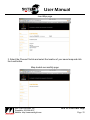
1
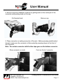
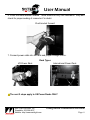
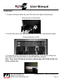
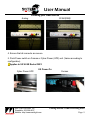
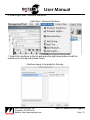
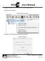
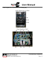
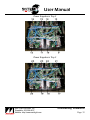
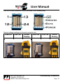
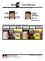
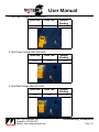
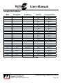
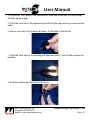
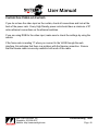
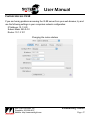
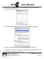
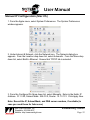
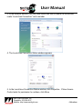
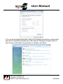
User Manual
This user manual is designed to help the operators and owners of Soft-LED products
use, troubleshoot, and utilize all of the product’s potential.
Customers seeking additional help not mentioned in this user manual should contact
Main Light Industries. Please use the “Contact Us” page in the back of this manual or
your Soft-LED contact.
Main Light Industries, Inc.
402 Meco Drive
Wilmington, DE 19804
Telephone: 302.998.8017
Fax: 302.998.8019
Table of Contents
Getting Started
Curtains and Power Racks
VLSE Rack
VLSE Adjustments
Previsualization Guide
Final Cut Pro
Video Resolution Guide
2 Medium-X Resolution Curtains
1 Medium-X Resolution Curtain
1 High Resolution Curtain
How To:
Address Power Supplies
Load Video Maps
Troubleshooting
Identification
Sample Rack Matrix
Troubleshooting Guide
Replacing a Node
Cannot See Video on Curtain
Cannot Access VLSE
Manual IP Configuration (Windows)
Manual IP Configuration (Mac OS)
Contact Us
4
8
11
13
17
19
21
23
28
31
40
42
43
46
47
48
52
53
User Manual
Getting Started
Curtains and Power Racks
1. Before connecting any part of the system, visually check for loosening of any
cables, etc. from shipping vibration.
2. Remove curtain from case by removing lid and flipping case up on end. Handle
by the edges only.
Properly remove the curtain from the case
3. Tie drapery onto support system.
Secure drapery tightly
Main Light Industries, Inc.
Telephone: 302.998.8017
Website: http://www.mainlight.com
Getting Started: Curtains and Power Racks
Page: User Manual
4. Remove caps from Multipin connector by pulling back on the metal part of the
connector and pushing down on the cap.
Pull bracket back
Remove cap
5. Place connector on mating connector of the rack. Before pressing metal bracket
forward, make sure the connector is fully seated by pressing down on the front of
the connector.
Note: The curtain connector with the blue tape goes on the bottom connector
Place connector on mate
Main Light Industries, Inc.
Telephone: 302.998.8017
Website: http://www.mainlight.com
Push on front of connector
Getting Started: Curtains and Power Racks
Page: User Manual
6. Press the metal bracket forward. There should be very little resistance. Stop and
check for proper seating of connector if in doubt.
Push bracket forward
7. Connect power cable into the rack and proper voltage source.
Rack Types
US Power Rack
International Power Rack
The next 2 steps apply to US Power Racks ONLY
Main Light Industries, Inc.
Telephone: 302.998.8017
Website: http://www.mainlight.com
Getting Started: Curtains and Power Racks
Page: User Manual
8. Push Power button on Cyber Power unit (UPS).
Power on Cyber Power UPS
9. Press Power switch on Furman unit.
Power on Furman
Note: You should see a power on test pattern on the curtain.
Main Light Industries, Inc.
Telephone: 302.998.8017
Website: http://www.mainlight.com
Getting Started: Curtains and Power Racks
Page: User Manual
VLSE Rack
1. Connect a ethernet cable into one of the rack’s front panel ethernet jacks.
Plug ethernet in Power Rack
2. Connect the other end of the ethernet cable to the Video Light System Engine.
Connect ethernet to VLSE
3. Connect the white canopus box to the video signal. If you need to change the
input signal, press the grey button on the left side of the canopus.
Note: There should already be a firewire cable between the VLSE and the rear
of the canobus box
Main Light Industries, Inc.
Telephone: 302.998.8017
Website: http://www.mainlight.com
Getting Started: Visual Processing Rack
Page: User Manual
Analog
Choosing your Video Source
SVGA(RGB)
4. Ensure that all connects are secure.
5. Push Power switch on Furman or Cyber Power (UPS) unit. (Varies according to
configuration)
Applies to US VLSE Racks ONLY
US Power On
Cyber Power UPS
Main Light Industries, Inc.
Telephone: 302.998.8017
Website: http://www.mainlight.com
Furman
Getting Started: Visual Processing Rack
Page: User Manual
Note: If you are sending a proper video signal, you should see the video on
the reference monitor and the curtain.
Video active on reference monitor
If you do not see the video input on the curtain, please refer to the
troubleshooting section of this manual.
Main Light Industries, Inc.
Telephone: 302.998.8017
Website: http://www.mainlight.com
Getting Started: Visual Processing Rack
Page: 10
User Manual
VLSE Adjustments
If the image does not fill the entire curtain, press the overscan button on the canopus
remote.
Canopus Remote
You may need to tweak the settings for RGB on the canopus via the remote also.
There are settings for Brightness, Contrast, Color, Sharpness, Flicker, and RGB gain.
Use the up and down arrows to change the settings accordingly.
When you are finished, press OK to save the settings.
If you have a signal connected, press the test button to display a test pattern.
Press OK when done.
Note: Analog signals may require the map to be adjusted.
Main Light Industries, Inc.
Telephone: 302.998.8017
Website: http://www.mainlight.com
Getting Started: VLSE Adjustments
Page: 11
User Manual
The dip switches on the bottom of the canopus should already be configured.
Switch 3 on block A enables the remote control.
Switches 6/7/8 on block A provide RGB termination.
Switch 5 on block B enables 7.5 or 0 IRE.
Note: The US video signal is 7.5 IRE and NTSC Format
Block A
Block B
Main Light Industries, Inc.
Telephone: 302.998.8017
Website: http://www.mainlight.com
Getting Started: VLSE Adjustments
Page: 12
User Manual
Previsualization Guide
Final Cut Pro
Here is a quick overview of setting up a movie in Final Cut Pro for usage on the SoftLED curtain. Other video editing programs should have similar settings available.
Note: The screenshots represent approximate settings.
1. Create a layer with your original video and place your video on this layer.
2. Apply a Gausian Blur to this layer.
Main Light Industries, Inc.
Telephone: 302.998.8017
Website: http://www.mainlight.com
Previsualization Guide: Final Cut Pro
Page: 13
User Manual
3. Create a layer above your video layer.
4. Import one of the animation templates.
Main Light Industries, Inc.
Telephone: 302.998.8017
Website: http://www.mainlight.com
Previsualization Guide: Final Cut Pro
Page: 14
User Manual
5. Apply a Luma Key filter to this new layer.
Main Light Industries, Inc.
Telephone: 302.998.8017
Website: http://www.mainlight.com
Previsualization Guide: Final Cut Pro
Page: 15
User Manual
Main Light Industries, Inc.
Telephone: 302.998.8017
Website: http://www.mainlight.com
Previsualization Guide: Final Cut Pro
Page: 16
User Manual
Video Resolution Guide
2 Medium-X Resolution Curtains
Medium-X Res Panels (16’1”H x 33’5”W)
2 Panels combined for 16’1H x 66’10”W
VLSE Output Resolution: 2000 pixels x 500 pixels
Desired Image
Main Light Industries, Inc.
Video Resolution Guide: 2 Med-X Res Curtains
Telephone: 302.998.8017
Page: 17
Website: http://www.mainlight.com
User Manual
Required 720x480 input to VLSE for properly scaled image
Resulting Image
Main Light Industries, Inc.
Video Resolution Guide: 2 Med-X Res Curtains
Telephone: 302.998.8017
Page: 18
Website: http://www.mainlight.com
User Manual
1 Medium-X Resolution Curtain
Medium-X Res Panel (16’1”H x 33’5”W)
1 Panel for 16’1H x 33’5”W
VLSE Output Resolution: 1010 pixels x 500 pixels
Desired Image
Main Light Industries, Inc.
Telephone: 302.998.8017
Website: http://www.mainlight.com
Video Resolution Guide: 1 Med-X Res Curtain
Page: 19
User Manual
Required 720x480 input to VLSE for properly scaled image
Resulting Image
Main Light Industries, Inc.
Telephone: 302.998.8017
Website: http://www.mainlight.com
Video Resolution Guide: 1 Med-X Res Curtain
Page: 20
User Manual
1 High Resolution Curtain
High Res Panel (8’1”H x 33’5”W)
1 Panels for 8’1H x 33’5”W
VLSE Output Resolution: 1020 pixels x 260 pixels
Desired Image
Main Light Industries, Inc.
Telephone: 302.998.8017
Website: http://www.mainlight.com
Video Resolution Guide: 1 High Res Curtain
Page: 21
User Manual
Required 720x480 input to VLSE for properly scaled image
Resulting Image
Main Light Industries, Inc.
Telephone: 302.998.8017
Website: http://www.mainlight.com
Video Resolution Guide: 1 High Res Curtain
Page: 22
User Manual
How To:
Address Power Supplies
Main Light uses the following naming conventions:
MLI SoftLED [Complete Rack Number][4 digit power supply number]
Example: “MLI SoftLED 43120001”
10.[Rack Series].[Rack Number].[Power Supply Number]
Example: “10.43.12.1”
Low Density Racks are 4000 series
High Density Racks are 4100 series
International Racks are 4200 series
Broadway Boxes are 4300 series
Customer Specials are 4500 series.
For more information, consult the Sample Rack Matrix in the
Troubleshooting section of this manual.
1. Launch “KinetInterfaceConfigTool” program located in the Light System
Composer/Utilities directory.
Light System Composter directory
Main Light Industries, Inc.
Telephone: 302.998.8017
Website: http://www.mainlight.com
Utilites directory
How To: Address Power Supplies
Page: 23
User Manual
This screen should appear
2. Select a power supply, type in a new name, and click Set beside the name.
Note: The display will automatically refresh
3. Type IP address and click on Set beside the address.
Remember to use the proper IP address naming convention
Note: The display will NOT refresh
4. Use File > Refresh to make the power supply reappear with the new address.
File > Refresh will make the power supply reappear
5. Launch the Management Tool.
Main Light Industries, Inc.
Telephone: 302.998.8017
Website: http://www.mainlight.com
How To: Address Power Supplies
Page: 24
User Manual
6. Select Light View > Discover Interfaces.
Light View > Discover Interfaces
7. Select ALL interfaces in the list and press the right arrow button to add the
interfaces to the map and choose Finish.
Interfaces ready to be added to the map
Main Light Industries, Inc.
Telephone: 302.998.8017
Website: http://www.mainlight.com
How To: Address Power Supplies
Page: 25
User Manual
8. Right Click (Mac OS: Control Click) on a power supply name.
9. Select Discover Lights.
Menu w/ Discover Lights
10. Make sure 100 lights were found and select Next.
Lights Discovered
Main Light Industries, Inc.
Telephone: 302.998.8017
Website: http://www.mainlight.com
How To: Address Power Supplies
Page: 26
User Manual
11. Check options and select Finish.
Proper Options
The tool will add 2 outputs to the power supply and the nodes
2 outputs created
Main Light Industries, Inc.
Telephone: 302.998.8017
Website: http://www.mainlight.com
How To: Address Power Supplies
Page: 27
User Manual
Load Video Maps
1. Launch a web browser and goto “http://10.1.3.101”. (without quotes)
If you cannot access this IP, see the Network Troubleshooting section
A screen similiar to this should appear
If System Status Settings shows a frame rate of “0” then there is a problem
with the firewire connection
2. Select the Load Map link on the left.
Note: If you have a CD in the drive of the Video Light System Engine (VLSE),
the map files will be listed.
Main Light Industries, Inc.
Telephone: 302.998.8017
Website: http://www.mainlight.com
How To: Load Video Maps
Page: 28
User Manual
Load Map page
3. Select the Choose File link and select the location of your saved map and click
the Load button.
Map loaded successfully page
Main Light Industries, Inc.
Telephone: 302.998.8017
Website: http://www.mainlight.com
How To: Load Video Maps
Page: 29
User Manual
4. Select the Set Region link if needed.
Note: If you are using all regions, select All and choose Set
5. Select the Load Gamma link.
Page with gamma file links
6. Select the desired gamma file and click the Load button.
Note: The gamma file sets the threshold at which the VLSE will ignore data.
If there is a lot of video “noise” in the system, you may need to use a higher
minus gamma file
Feel free to use the Map Info and Log File links to see if there are any problems.
The Backup link allows you to save the map file loaded on the VLSE. Once the
page loads, Right Click (Mac OS: Control Click) to save the linked file to your
computer.
Main Light Industries, Inc.
Telephone: 302.998.8017
Website: http://www.mainlight.com
How To: Load Video Maps
Page: 30
User Manual
Troubleshooting
Identification
Strings and Nodes can be identified in the following way:
Medium Resolution Panel Detail
Main Light Industries, Inc.
Telephone: 302.998.8017
Website: http://www.mainlight.com
Troubleshooting: Identification
Page: 31
User Manual
Medium-X Resolution Panel Detail
Main Light Industries, Inc.
Telephone: 302.998.8017
Website: http://www.mainlight.com
Troubleshooting: Identification
Page: 32
User Manual
High Resolution Panel Detail
Main Light Industries, Inc.
Telephone: 302.998.8017
Website: http://www.mainlight.com
Troubleshooting: Identification
Page: 33
User Manual
Power supplies can be identified in the following way:
Power Supply Trays in a Rack
Power Supplies in Tray 1
Main Light Industries, Inc.
Telephone: 302.998.8017
Website: http://www.mainlight.com
Troubleshooting: Identification
Page: 34
User Manual
Power Supplies in Tray 2
Power Supplies in Tray 3
Main Light Industries, Inc.
Telephone: 302.998.8017
Website: http://www.mainlight.com
Troubleshooting: Identification
Page: 35
User Manual
Pins on the rack connectors can be identified in the following way:
Normal voltage readings on the rack connector are:
Lead One
Lead Two
Normal
Lead One
Reading
Ground
Power
~7.5VDC
Main Light Industries, Inc.
Telephone: 302.998.8017
Website: http://www.mainlight.com
Ground
Lead Two
Normal
Reading
Data
2.0-2.5VDC
Troubleshooting: Identification
Page: 36
User Manual
Pins on the cable connector can be identified in the following way:
Normal resistance readings on the cable connector are:
Lead One
Lead Two
Normal
Lead One
Reading
Ground
Power
~.5-.8Ω
Main Light Industries, Inc.
Telephone: 302.998.8017
Website: http://www.mainlight.com
Ground
Lead Two
Normal
Reading
Data
~1.0-1.2Ω
Troubleshooting: Identification
Page: 37
User Manual
In node strings, the wire types are as follows:
Wire piercing leads are needed to test node strings. If unavailable, create simple leads
using alligator clips and safety pins.
Pierce insulation ONLY. Do not go through wire.
Node replacement is necessary if there is data before the node but not after. Follow
these steps to properly determine whether a node needs replacement.
1. Test Power Voltage before the first node.
Lead One
Lead Two
Power
Main Light Industries, Inc.
Telephone: 302.998.8017
Website: http://www.mainlight.com
Ground
Normal
Reading
~7.5VDC
Troubleshooting: Identification
Page: 38
User Manual
2. Test Data Voltage before first node.
Lead One
Lead Two
Power
Data
3. Test Power Voltage after first node.
Lead One
Lead Two
Power
Ground
4. Test Data Voltage after first node.
Lead One
Lead Two
Power
Main Light Industries, Inc.
Telephone: 302.998.8017
Website: http://www.mainlight.com
Data
Normal
Reading
2.0-2.5VDC
Normal
Reading
~7.5VDC
Normal
Reading
2.0-2.5VDC
Troubleshooting: Identification
Page: 39
User Manual
Sample Rack Matrix
Rack
PS Number
IP Address
Outputs
Connector-Pins
4201
0001
10.42.1.1
4201
0002
10.42.1.2
4201
0003
10.42.1.3
4201
0004
10.42.1.4
4201
0005
10.42.1.5
4201
0006
10.42.1.6
4201
0007
10.42.1.7
4201
0008
10.42.1.8
4201
0009
10.42.1.9
4201
0010
10.42.1.10
4201
0011
10.42.1.11
4201
0012
10.42.1.12
Out1
Out2
Out1
Out2
Out1
Out2
Out1
Out2
Out1
Out2
Out1
Out2
Out1
Out2
Out1
Out2
Out1
Out2
Out1
Out2
Out1
Out2
Out1
Out2
Blue-1
Blue-2
Blue-3
Blue-4
Blue-5
Blue-6
Blue-7
Blue-8
Blue-9
Blue-10
Blue-11
Blue-12
Blue-13
Blue-14
Blue-15
Blue-16
Blue-17
Blue-18
Blue-19
Blue-20
Blue-21
Blue-22
Blue-23
Blue-24
Continued on Next Page...
Main Light Industries, Inc.
Telephone: 302.998.8017
Website: http://www.mainlight.com
Troubleshooting: Sample Rack Matrix
Page: 40
User Manual
Rack
PS Number
IP Address
Outputs
Connector-Pins
4201
0013
10.42.1.13
4201
0014
10.42.1.14
4201
0015
10.42.1.15
4201
0016
10.42.1.16
4201
0017
10.42.1.17
4201
0018
10.42.1.18
4201
0019
10.42.1.19
4201
0020
10.42.1.20
4201
0021
10.42.1.21
4201
0022
10.42.1.22
4201
0023
10.42.1.23
4201
0024
10.42.1.24
Out1
Out2
Out1
Out2
Out1
Out2
Out1
Out2
Out1
Out2
Out1
Out2
Out1
Out2
Out1
Out2
Out1
Out2
Out1
Out2
Out1
Out2
Out1
Out2
Green-1
Green-2
Green-3
Green-4
Green-5
Green-6
Green-7
Green-8
Green-9
Green-10
Green-11
Green-12
Green-13
Green-14
Green-15
Green-16
Green-17
Green-18
Green-19
Green-20
Green-21
Green-22
Green-23
Green-24
Main Light Industries, Inc.
Telephone: 302.998.8017
Website: http://www.mainlight.com
Troubleshooting: Sample Rack Matrix
Page: 41
User Manual
Troubleshooting Guide
Symptom
Cause
Solution
Random pattern on curtain
No VLSE signal
Only part of the curtain is
working properly
Power is disconnected from either
a Power Supply tray or an Ethernet
switch
Scan Convertor is not configured
1. Adjust the overscan setting on the
correctly
coverter via the remote
2. Increase the image area in the Video
Management Tool
Power Supply is not functioning
1. Check the Ethernet connections for
correctly
the Power Supply
2. Check that the connectors plugged
into the Power Supply are working
correctly
3. Check the power indicator on
the Power Supply, if it is not
functioning, replace Power Supply
Data is not going to the first LED
1. Check voltage at the multipin rack
in the line
connector, if there is no voltage
present, check the Power Supply
(see above)
2. Check the voltages (power and data)
before the first node
3. Check the voltages (power and data)
after the first node
4. If a voltage is not present before the
first node, check all connections
5. If the voltages are correct before but
not after the first node, then replace
the first node
The LED map is incorrect
Adjust the video map
-Even numbered curtains have the
LEDs run left to right
-Odd numbered curtains have the
LEDs run right to left
There are 2 to 4 lines of LEDs
around the entire image that
are not working
There are 2 lines of LEDs that
are not working
There is 1 line of LEDs not
working
Image on curtain is reversed
Main Light Industries, Inc.
Telephone: 302.998.8017
Website: http://www.mainlight.com
1. Check Ethernet connection between
VLSE Rack and Power Rack
2. Ensure the VLSE is receiving a
proper video signal
Check all internal power connections
Troubleshooting: Guide
Page: 42
User Manual
Replacing a Node
1. Score the glue holding the node to the washer with side angle cutters.
2. Use linesman pliers to grab the node by its sides and hold the washer. Gently
twist to remove the node from the curtain.
3. Remove the backing of the node by using the linesman pliers at a 30° angle to
the plane of the node (1/8” from the back) and applying pressure. The node will be
free to remove from the wire.
Note: There will be holes in the wire from the node.
Main Light Industries, Inc.
Telephone: 302.998.8017
Website: http://www.mainlight.com
Troubleshooting: Replacing a Node
Page: 43
User Manual
4. Locate the “Out” label on the replacement node and make sure this faces away
from the power supply.
5. Push the front half of the replacement node into the wires where you removed the
node.
6. Secure one side of the backing by hand. It will make a click sound.
7. Push the other side of the backing with linesman pliers. Use as little pressure as
possible.
8. Grab the washer and push the node into it.
Main Light Industries, Inc.
Telephone: 302.998.8017
Website: http://www.mainlight.com
Troubleshooting: Replacing a Node
Page: 44
User Manual
9. Glue the node back onto the curtain.
An alternative to replacing the node is to use butt splices.
Main Light Industries, Inc.
Telephone: 302.998.8017
Website: http://www.mainlight.com
Troubleshooting: Replacing a Node
Page: 45
User Manual
Cannot See Video on Curtain
If you do not see the video input on the curtain, check all connections and look at the
back of the power rack. Every High Density power rack should have a minimum of 27
active ethernet connections on the ethernet switches.
If you are using RGB for the video input, make sure to check the settings by using the
remote.
If the frame rate is reading “0” when you connect to the VLSE through the web
interface, this indicates that there is a problem with the firewire connection. Ensure
that the firewire cable is securely seated in both ends of the cable.
Main Light Industries, Inc.
Telephone: 302.998.8017
Website: http://www.mainlight.com
Troubleshooting: Video
Page: 46
User Manual
Cannot Access VLSE
If you are having problems accessing the VLSE server from your web browser, try and
use the following settings in your computers network configuration:
IP Address: 10.1.3.20
Subnet Mask: 255.0.0.0
Router: 10.1.3.101
Changing the router address
Main Light Industries, Inc.
Telephone: 302.998.8017
Website: http://www.mainlight.com
Troubleshooting: Network
Page: 47
User Manual
Manual IP Configuration (Windows)
1. From the Start menu select Settings>Control Panel. Click the Network and
Internet Connections.
2. From the Network and Internet Connections window, click Network Connections.
Main Light Industries, Inc.
Telephone: 302.998.8017
Website: http://www.mainlight.com
Troubleshooting: Network
Page: 48
User Manual
3. Double Click the Local Area Connection icon.
4. The Local Area Connection Status window appears.
5. In the Local Area Connection Status window, click Properties. The Local Area
Connection Properties window appears.
Main Light Industries, Inc.
Telephone: 302.998.8017
Website: http://www.mainlight.com
Troubleshooting: Network
Page: 49
User Manual
6. Click to highlight Internet Protocol (TCP/IP), then click Properties. The Internet
Protocol (TCP/IP) Properties dialog appears.
7. Select Use the Following IP Address. In the IP Address field enter 10.1.3.20. In
the Subnet Mask field enter 255.0.0.0. The Router should be set to 10.1.3.101 to
ensure the connection works. Click OK.
Note: If an IP and DNS address are present, record these numbers for future
reference.
Main Light Industries, Inc.
Telephone: 302.998.8017
Website: http://www.mainlight.com
Troubleshooting: Network
Page: 50
User Manual
8. To turn off the firewall protection, click the advanced tab from the Local Area
Connection Properties window.
9. Click the Settings button and the Windows Firewall Status window appears.
10. Click the radio button to turn Off the Windows Firewall and click OK.
11. Click OK to return to the Local Area Connection Status window, then close. The
new IP address should take effect right away.
Main Light Industries, Inc.
Telephone: 302.998.8017
Website: http://www.mainlight.com
Troubleshooting: Network
Page: 51
User Manual
Manual IP Configuration (Mac OS)
1. From the Apple menu, select System Preferences. The System Preferences
window appears.
2. Under Internet & Network, click the Network icon. The Network dialog box
appears. From the Location drop down list, select Automatic. From the Show drop
down list, select Built-In Ethernet. Ensure that TCP/IP tab is selected.
3. From the Configure IPv4 drop down list, select Manually. Enter in the fields: IP
Address- 10.1.3.20, Subnet Mask- 255.0.0.0, Router- 10.1.3.101. Click Apply Now.
Note: Record the IP, Subnet Mask, and DNS server numbers, if available (in
case you need those for future use).
Main Light Industries, Inc.
Telephone: 302.998.8017
Website: http://www.mainlight.com
Troubleshooting: Network
Page: 52
User Manual
Contact Us
We are here to help you, contact us if you need any assistance.
Main Light Industries, Inc.
402 Meco Drive
Wilmington, DE 19804
Telephone: 302.998.8017
Fax: 302.998.8019
Main Light Website:
http://www.mainlight.com/
Soft-LED Customer Home:
http://www.mainlight.com/softled/customer/
After Hours Technical Support
[email protected]
Main Light Industries, Inc.
Telephone: 302.998.8017
Website: http://www.mainlight.com
Troubleshooting: Contact Us
Page: 53
User Manual
Manual IP Configuration (Windows Vista)
1. From the Start menu select Control Panel. Click Network and Internet.
2. From the Network and Internet window, click Network and Sharing Center.
Main Light Industries, Inc.
Telephone: 302.998.8017
Website: http://www.mainlight.com
Addendum
User Manual
3. In the Network section, click the View Status link next to where the connection
reads “Local Area Connection” and a number.
4. The Local Area Connection Status window appears.
5. In the Local Area Connection Status window, click Properties. If User Access
Control asks for permission to continue, click Allow.
Main Light Industries, Inc.
Telephone: 302.998.8017
Website: http://www.mainlight.com
Addendum
User Manual
The Local Area Connection Properties window appears.
6. Click to highlight Internet Protocol Version 4 (TCP/IPv4), then click Properties.
The Internet Protocol Version 4 (TCP/IPv4) Properties dialog appears.
Note: If an IP and DNS address are present, record these numbers for future
reference.
7. Select Use the Following IP Address. In the IP Address field enter 10.1.3.20.
In the Subnet Mask field enter 255.0.0.0. The Default Gateway should be set to
10.1.3.101 to ensure the connection works. Leave both of the DNS fields empty
and Click OK. Click OK to close the Local Area Connection Properties and Local
Area Connection Status windows. These settings should now be applied.
Main Light Industries, Inc.
Telephone: 302.998.8017
Website: http://www.mainlight.com
Addendum
User Manual
8. To turn off the firewall protection, return to the Network and Internet control panel
and click Turn Windows Firewall On or Off under the Windows Firewall section. If
User Access Control asks for permission to continue, click Allow.
Main Light Industries, Inc.
Telephone: 302.998.8017
Website: http://www.mainlight.com
Addendum
User Manual
9. Click the radio button to turn Off the Windows Firewall and click OK. All windows
can now be closed.
Main Light Industries, Inc.
Telephone: 302.998.8017
Website: http://www.mainlight.com
Addendum