1
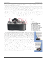
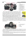
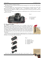
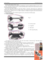
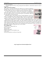
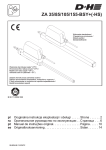
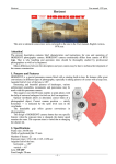
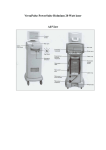
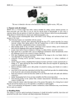
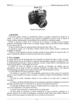
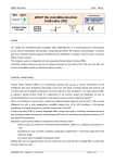
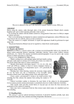
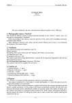
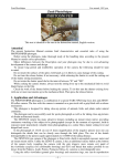
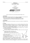
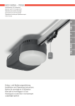
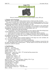
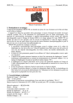
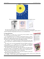
Zenit-C (Zenit S)
User manual, 1955 year
Zenit C (Zenit S)
This text is identical to the one in the Instruction manual, English version.
The Instruction Manual contains essential principles of “Zenith-C” camera operation.
To avoid possible breakage of the camera and to obtain good pictures thoroughly acquaint yourself
with the construction and operation of the camera as it is described below.
I. General Features
The “Zenith-C” is a mirror type 35 mm film precision miniature camera
possessing all the merits of up-to-date cameras.
It is recommended for use by amateurs to photograph landscape, portraits,
groups, separate sport scenes, etc. It can also be used in research institutes and
laboratories for photographing through various optical instruments: for instance,
the camera can be conveniently used for taking photomicrographs.
The “Zenith-C” uses a standard perforated 35 mm motion picture film about
1,6 m in length. This is sufficient for making up to 36 exposures 24x36 mm in
size.
The camera can be used for photographing under poor lighting conditions or
in full darkness as it is adapted for use of flash bulbs. A controllable
synchronizing mechanism with an advanced scale ranging from 0 to 25 millisec.
permits photographing with flash bulbs of various types.
The camera is of the mirror type. The image thrown by the mirror onto a
frosted glass surface is viewed through an eyepiece, the axis of which is parallel
to the lens axis. The viewed image is direct. The eyepiece magnification is 5x.
The field of vision seen through the eyepiece is 20x28 mm.
The camera has been designed for use with metal magazines which open
automatically upon closing the camera cover.
The camera is furnished with a curtain-type shutter giving automatic exposure speeds ranging from
1/25 to 1/500 sec. The “B”-hand exposure setting is employed.
–1–
Zenit-C (Zenit S)
User manual, 1955 year
The camera mechanism makes long “T” (originally: “Д” – Cyrillic “D”)
exposure possible. The shutter is coupled with both the film advancing
mechanism and the automatic film counter, so that winding the shutter
automatically transports the film after each exposure and the film counter
indicates the number of exposure taken. It prevents accidental double exposure
on the same part of the film.
The shutter release is interlocked with the mirror lift to prevent cutting-off of
the pictures due to the negative field being not fully open.
The camera provides a possibility of reloading in ordinary, but not too bright,
light.
II. Specifications
Size of film – 35 mm
Size of picture – 24x36 mm
Film magazine capacity – 36 pictures
“Industar-22” or “Industar-50”
coated lens:
focal length – 50 mm
full aperture – f/3.5
Lens opening scale – 3.5; 4; 5.6; 8; 11; 16
Distance scale – 0,65 m to infinity
Shutter exposure speeds – 1/25; 1/50; 1/100; 1/250; 1/500 sec., Bulb (“B”) and Time (“T”) (originally:
“Д” – Cyrillic “D”)
Synchronizing mechanism scale – 0 to 25 millisec.
Camera overall dimensions – 78x90x138 mm
Camera weight – 630 g
III. Camera Construction
The mirror type view-finder diagram is shown in Fig. 1. It operates together
with camera lens 1 and consists of swivel mirror 2, plane-convex lens 3, the
plane surface of which is frosted, penta-prism 4 and triple-lens eyepiece 5.
With the mirror in its upper position 2' the camera gives an inverted image on
film plane 6. With the mirror down, the image is received on the frosted plane of
lens 3. The image sharpness on the frosted lens 3 plane is just the same as on the
film plane. The inverted image of the subject given by the camera lens is again
inverted by mirror 2 and prism 4, and comes to the eye through eyepiece 5, as a
straight image.
To wind the shutter turn winding knob 8 (Fig. 2) as far as it will go in the direction indicated by the
arrow engraved on the top cover. At the same time, this will move the film, lower the view-finder
mirror, wind the shutter and bring into action the snap-shot counter.
Fig. 1
1 – camera lens
2 – swivel mirror
3 – plane-convex lens with frosted plane
surface
4 – penta-prism
5 – triple-lens eyepiece
6 – film plane
–2–
Zenit-C (Zenit S)
User manual, 1955 year
The snap-shot counter dial 9 is set at zero by rotating its knurled end in either direction. The number
of exposures is read off by means of black pointer 10 engraved on the upper side of the camera. Set the
counter at zero with the shutter wound up.
The shutter is released by pressing the release button 11 which has a conical thread to accommodate
a cable release. The exposure speeds are changed by a little lifting and turning the exposure setting
ring 12 until the index line 13 is opposite figure indicating the desired speed. The ring 12 may be
turned only through the part of the scale marked B, 25, 50, 100, 250, 500 and back.
Do not turn it in the interval between B and 500
The figures on the scale indicate exposure speeds in fractions of a second, for example 50 instead of
1/50, 100 instead of 1/100, etc. Longer exposures “T” (originally: “Д” – Cyrillic “D”) are obtained
with the ring 12 set at “B”. In this case press the release button 11 and turn it so that the pint engraved
on it moves towards the letter “T” (originally: “Д” – Cyrillic “D”) as far as it will go. When the
exposure is to be ended move the release button back and release it.
Fig. 2
5 – eyepiece
7 – adjusting ring
8 – shutter winding knob
9 – snap-shot counter dial
10 – counter pointer
11 – shutter release button
12 – exposure setting ring
13 – exposure setting indicator
15 – film rewinding knob
16 – synchronizing lever
17 – synchronization scale
To wind the film back into the magazine, with the shutter released, turn the
ring 7 so that the point engraved on it moves towards the letter “R” (originally:
“П” – Cyrillic “P”, from ‘перемотка’, ‘peremotka’ – rewinding) to a stop. Then,
wind the film by rotating the film rewinding knob 15 in the direction indicated
by the arrow. The knob should be rotated until the force required to rotate is
decreased. This shows that the film has been bully rewound and is completely in
the magazine.
The lens is tightly screwed into the ring and has the mounting 19 (Fig. 3)
with the distance scale. The distance set is shown by the red index 20.
The lens opening can be changed by rotating the objective front ring 21 until
the necessary division comes opposite the index point 22. For convenient
changing of the lens opening three lens opening scales are engraved on the ring
21. They have three corresponding index points 22.
The lens design enables lens opening to be set with filters on.
The lens is provided with the depth of field scale 23. The depth of field is the
distance between the nearest and the farthest objects in a scene which will be
sharp in the picture. The depth of field increases as the lens opening is made
smaller, or as the distance focused upon is increased.
–3–
Zenit-C (Zenit S)
User manual, 1955 year
Fig. 3.
1 – lens
7 – adjusting ring
11 – shutter release button
14 – plug socket
15 – film rewinding knob
16 – synchronizing lever
17 – synchronization scale
19 – distance scale ring
20 – distance scale pointer
21 – lens front ring
22 – lens opening scale pointer
23 – depth of field scale
When it is possible to photograph objects of considerable depth or a number
of objects at different distances, reference to the depth of field scale which will
cover objects at both positions. After focusing, this scale shows the limits of the
depth of field for the diaphragm scale setting used. The depth field ranges from
the diaphragm scale figure on one side of the indicator to the same on the other.
For instance, suppose the lens is focused for a distance of 4 m with a diaphragm
setting of 16. Then the image will be sufficiently sharp between 2 m and
infinity. With the same focus setting for distance of 4 m but with a diaphragm
figure of 5.6, the image will be sufficiently sharp between 3 and 7 m.
The flash synchronizing mechanism with its scale, having a range of 0 to 25
millisec., permits photographing with flash bulbs of any type. The bulb is connected to the camera by
means of the socket 14. An illuminating single-flash bulb device is fixed to the bottom cover of the
camera by means of the bracket and the tripod screw. Flash bulbs of different types differ in the flash
duration necessary to produce light approximately to one half of the bulb peak after the switch closes.
This value (in millisec.), usually determined from the bulb certificate, should be set on the
synchronization scale 17 by turning the lever 16 until the lever index is opposite the corresponding
division of the scale.
Fig. 4.
18 – objective fastening ring
25 – camera tripod nut
26 – latch
27 – eyelets
28 – latch ring
When photographing with a multi-flash impulse bulb it must be remembered that its lag equals
practically zero. Therefore, when using a bulb on this kind, the lever 16 should be set at “0”. The
illuminator of a multi-flash impulse bulb is usually fastened to the tripod nut of the camera, but may
also set up at same distance, depending on the length of the conductor connecting the impulse device
with socket 14 on the camera.
The use of the flash bulbs is possible only with exposure speeds of 1/25 sec. and “B”. “B” exposure
are usually undesirable when using flash bulbs, as during long exposures a large amount of light enters
the camera, which may result in a double image.
–4–
Zenit-C (Zenit S)
User manual, 1955 year
The camera is fixed in its case or on a tripod without its case by means of nut 25 (Fig. 4) in the
bottom cover, having a standard 3/8" thread.
The bottom cover is also provided with latch 26 for locking the cover and at the same time opening
the slit in the magazine.
To open the bottom cover, turn the latch ring 28 counter-clockwise so that the arrow on the latch
points to the engraving “Open” (originally: “откр.” – an abridgment to Cyrillic ‘открыто’ – open).
Then open the cover. Magazine 36 (Fig. 5) and take-up spool 30 are fitted loosely into the camera and
can be easily removed.
Filters to be used with this camera should have mounting thread size of 33x0.5 mm and an external
diameter of 36 mm.
Fig. 5.
30 – take-up spool
36 – magazine
C – film track
IV. Magazine Loading
The magazine 36 consists of three parts: case 31, cartridge 32 and spool 33
(Fig.6). To open the magazine, press the button 34 and give the cartridge a halfturn clockwise until it comes freely out of case 31. After this spool 33 can be
removed. The subsequent loading operations should be carried out in red light or
in complete darkness, depending on the type of film used. Cut the end of the film
and, holding the spool with its head inwards, pass the end of the film through
one of the spool slits at its wide side. The sensitive side of the film should face
downwards.
Bend the end of the film protruding from the opposite (narrow) side of the slit
and pass it into the narrow side of the other slit. Then fold the very end of the film three times and pull
the film so as to wedge the folder end in the slit.
Fig. 6.
31 – magazine case
32 – magazine cartridge
33 – magazine spool
34 – magazine button
36 – magazine
After this, continuing to hold the spool with its head inwards, rotate it
–5–
Zenit-C (Zenit S)
User manual, 1955 year
counter-clockwise, winding the film with its sensitive side inside.
Wind the film tightly onto the spool.
Note. The film should not be tightened by holding the spool and pulling the film by its free end as
this may scratch the sensitive layer as a result of friction between the turns. Do not touch the sensitive
side of the film with your fingers.
Insert the spool with the film on it into the cartridge, so that the spool head passes through the
bottom of the cartridge. Insert the cartridge into the case, leaving the end of the film protruding out of
it and rotate the cartridge in its case counter-clockwise, holding the magazine with its head inwards,
until the latch locks.
All subsequent operations with the magazine can be carried out in ordinary light.
V. Camera Loading
Fig. 7.
30 – take-up spool
36 – magazine
C – film track
S – take-up spool spring
1. To engage the camera mechanism, turn the release button 11 and the ring 7 until their points
coincide with point on the camera top surface.
2. Test the operation of the camera winding the shutter by turning the knob 8
and releasing it by pressing the button 11. Take a look through the eyepiece to
see whether the mirror system is working properly.
3. Then, open the button cover and take out the take-up spool 30.
4. Draw the film end out of the magazine to a length of 9 or 10 cm and out it
carefully to a shape as shown in Fig. 7.
5. Holding the take-up spool 30 in your left hand and loaded magazine in your
right hand (see Fig. 7) fix the end of the film under spool spring “S” (originally:
“П” – Cyrillic “P”, from ‘пружина’, ‘proodzina’ – spring). Take care that the
uncut side of the film lies closely against the spool flange.
6. Holding the open camera with its lens outwards, as is shown in Fig. 7,
insert the film into the film track “C” (originally: “C” too, in Latin, from
‘channel’) by lowering the spool and the magazine evently into place. If the
–6–
Zenit-C (Zenit S)
User manual, 1955 year
magazine does not slide properly, film rewinding knob 15 should be turned a little until it does.
7. Replace the bottom cover, press it down tightly and give the latch ring 28 (Fig. 4) one-half turn
clockwise. The latch arrow should then point to “Close” (originally: “закр.” – an abridgment to
Cyrillic ‘закрыто’ – close). The magazine slit automatically opens freeing the film, as the lock is
closed.
8. To deliver an unexposed portion of the film to the negative window, wind up the shutter tree
times, pressing the release button 11 after each winding. When winding the shutter mechanism, check
to see whether film rewinding knob 15 is rotating.
If the knob does not rotate, check whether the film has been loaded into the camera correctly. Note
that this may also take place during the first few shots if the magazine was loaded with a film much
shorter than normal length. In this case the rewinding knob starts to rotate only when the film tension
on the spool is sufficient.
9. Set the picture counting dial 9 at “0” opposite the counter index 10.VI. Taking the pictures
The camera may be operated or set on a tripod or on horizontal surface.
When preparing to take the picture it is advisable to follow the steps listed
bellow:
1. Make sure that the shutter mechanism is engaged i.e. the points on the ring
7 and the release button 11 coincide with the point on the top side. Look at the
picture counting dial to make sure whether there is any unexposed film left in
the camera.
2. When using a flash bulb, screw the illuminator to the tripod nut on the
camera, set the synchronizing scale and connect the bulb to the camera as it is
described before.
3. If necessary, fix the camera to the tripod and screw the cable release into the release button.
4. Remove the lens cap.
5. If necessary, attach a filter.
6. Open the lens opening fully by turning the front lens ring 21 until it stops.
Just before taking a picture it is necessary:
1. Wind the shutter by turning the shutter winding knob 8 in the direction of
the arrow as far as it will go.
2. Determine the required exposure speed and set it with the exposure setting
ring 12 as indicated before.
3. Adjust correct focus by turning the knurled ring 19 and viewing the image
of the object through the eyepiece 5.
Note. If the image remains sharp when the ring is rotated through a certain
angle, it should be set in the middle of that angle.
4. Set the required lens opening by turning the ring 21. When setting the lens opening it is
recommended to hold the ring 19 in order to avoid unfocusing of the camera.
5. Make the exposure by slowly pressing the release button 11. Take care not to move the camera
during the exposure, or the picture may be blurred.
When taking the picture with the camera in the carrying case, see that the case cover does not get
between the object and the lens.
VII. Camera Unloading
When the film is entirely exposed the camera has to be unloaded. For this purpose:
1. Cover the lens with its cap.
2. Turn the ring 7 so that its point moves towards the letter “R” (originally: “П” – Cyrillic “P”, from
‘перемотка’, ‘peremotka’ – rewinding) to a stop.
3. Rewind the film back into the magazine by rotating the film rewinding knob 15 in the direction
indicated by the arrow.
4. Open the camera as described before.
Note. When opening the camera, the magazine slit closes automatically, therefore, to avoid spoiling
the film, the cover should not be removed until the lock is at a stop.
5. Remove the magazine from the camera.
–7–
Zenit-C (Zenit S)
User manual, 1955 year
6. Turn the ring 7 until its point is opposite to that on the upper side of the camera. This re-engages
the camera mechanism.
7. Wind the shutter and release it by pressing the release button 11. After this the camera is ready to
be reloaded.
VIII. Care of the camera
The camera is a precision instrument and should receive careful and intelligent
handling. Keep the camera in its carrying case, isolated from dust, dampness and
dirt. Do not subject the camera to sudden and extreme temperature variations.
It is quite evident that such a delicate and accurate piece of equipment as
coated lens requires special care and can be easily ruined by careless handling.
The coated surface of lenses are covered with special, very thin films, which can
be easily spoiled, if cleaned carelessly.
Should the surfaces show deposits of dust or other impurities do not try to
remove it by rubbing the surfaces with your fingers. Dust may be removed with
a clean soft brush, a clean (well washed) flannel, calico or muslin napkin.,
chamais or cotton wool, without exerting pressure on the surface being cleaned.
Finger prints sweating traces, etc. may be removed by wiping without pressure with a clean napkin
slightly moistened with rectified alcohol. Any stains should be removed with a dry napkin. Do not
expose the lens for long periods to direct rays of the sun. It is not advisable to screw the lens out of the
camera without necessity. If, however, the lens has to be screwed out to exchange it for another lens
with a different focal length, the parts of the mechanism and the optical parts of the view-finder (the
frosted glass and mirror) should not in any case be touched.
IX. Camera Set
“Industar-22” or “Industar-50” lens
Lens covering cap
Take-up spool
Magazine with spool
Leather carrying case with shoulder strap
Cable release
Instruction manual and certificate of inspection
http://eugigufo.net/en/download/photovideo/
–8–