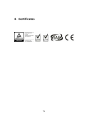
1
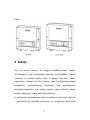
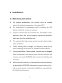
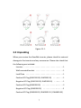
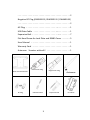
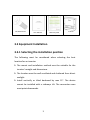
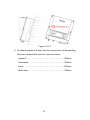
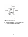
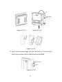
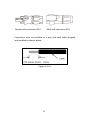
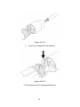
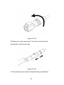
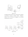
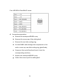
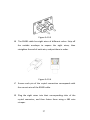
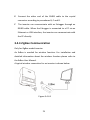
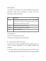
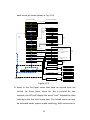
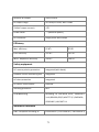
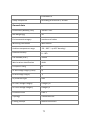
User Manual GOODWE SS SERIES Ver 04 Table of Contents 1 Symbols ................................................................................1 2 Safety ...................................................................................3 3 Installation ...........................................................................6 3.1 Mounting Instruction ......................................................6 3.2 Unpacking ......................................................................7 3.3 Equipment Installation ....................................................9 3.3.1 Selecting the installation position ..................................... 9 3.3.2 Mounting Procedure ....................................................... 11 3.4 Electrical Connection .................................................... 14 3.4.1 Connection to grid (AC side Connection) ........................ 14 3.4.2 DC side connection ......................................................... 17 3.4.3 RS485 Communication .................................................... 24 3.4.4 ZigBee Communication ................................................... 28 3.4.5 WiFi Communication ..................................................... 29 3.4.6 Communication with Solar-Log Device ........................... 43 3.4.7 USB Communication ....................................................... 45 3.5 Troubleshooting............................................................ 46 4 System Operation ............................................................... 51 4.1 Operating Panel ............................................................ 51 4.2 Indicator Lights ............................................................. 51 4.3 LCD Display ................................................................... 52 4.4 Error messages ............................................................. 61 4.5 WiFi Reset&Reload……………………………………….…………….. 49 4.6 Zigbee ID RESET ............................................................ 64 5 Technical Parameters .......................................................... 66 6 Certificates......................................................................... 78 7 Warranty ........................................................................... 79 7.1 Warranty Period ........................................................... 79 7.2 Warranty Card .............................................................. 79 7.3 Warranty Conditions ..................................................... 79 7.4 Scope of Warranty ........................................................ 80 8 Contact ............................................................................... 81 Notes: The images and diagrams in this manual are for guidance only. Please refer to the actual product. 1 Symbols Caution! - Failure to observe a warning indicated in this manual may result injury. Danger of high voltage and electric shock! Danger of hot surface! Product should not be disposed as household waste. This side up; the package must always be transported, handled and stored in such a way that the arrows always point upwards. Components of the product can be recycled. Fragile; the package/product should be handled carefully and never be tipped over or slung. No more than six (6) identical packages may be stacked on each other. Keep dry; the package/product must be protected from excessive humidity and must be stored under cover. 1 CE Mark Residual voltage exists in the inverter; before commencing any maintenance, at least 5 minutes must be allowed for the capacitor in the inverter to fully discharge. 2 Units: 2 Safety The SS series inverter of Jiangsu GoodWe Power Supply Technology Co. Ltd. ( hereinafter referred to as GoodWe ) strictly conforms to related safety rules in design and test. Safety regulations relevant to the location shall be followed during installation, commissioning, operation and maintenance. Improper operation may cause serious injury, electric shock and/or damage to equipment and property. Installation, maintenance and connection of inverters must be performed by qualified personnel, in compliance with local 3 electrical standards, regulations and the requirements of local power authorities and/or companies. To avoid electric shock, DC input and AC output of the inverter must be terminated at least 5 minutes before performing any installation or maintenance. The temperature of some parts of the inverter may exceed 60℃ during operation. To avoid being burnt, do not touch the inverter during operation. Let it cool before touching it. Ensure children are kept away from inverters. Do not open the front cover of the inverter. Apart from performing work at the wiring terminal (as instructed in this manual), touching or changing components without authorization may cause injury to people, damage to inverters and annulment of the warranty. Static electricity may damage electronic components. Appropriate methods must be adopted to prevent such damage to the inverter; otherwise the inverter may be damaged and the warranty annulled. Ensure the output voltage of the proposed PV array is lower than the maximum rated input voltage of the inverter , otherwise the inverter may be damaged and the warranty annulled. when the photovoltaic array is exposed to light, it supplies a d.c 4 voltage to the PCE. PV modules should have an IEC61730 classA rating. If the maximum AC mains operating voltage is higher than the PV array maximum system voltage ,PV modules should have a maximum system voltage rating based upon the AC mains voltage. If the equipment is used in a manner not specified by the manufacturer, the protection provided by the equipment may be impaired. Completely isolate the equipment should :switch off the DC switch ,disconnect the DC terminal ,and disconnect the AC terminal or AC breaker. Prohibit inserting and pulling the AC and DC terminals when the inverter is working. Warning: Not to enter other areas of the equipment when maintenance! 5 3 Installation 3.1 Mounting Instruction A For optimal performance, the inverter must be located where the ambient temperature is less than 45 °C. B For convenience in maintenance and in checking the LCD display, install the inverter at eye level. C Inverters should NOT be installed near flammable and/or explosive items. Any electro-magnetic equipment should be kept away from the installation site. D The product label and warning symbol must be clearly visible after installation. E Please avoiding direct sunlight, rain Exposure, snow lay up when installing, this is better for extended inverter lifetime. F During installation, if those unused terminals are not plugged, thus causing water and moisture goes into the inverters and inverters not work, GOODWE will not bare the liability and warranty. G While install the inverter, it is demanded to use the accessory kit provided by GOODWE, otherwise the inverter may not be able to work properly, and neither GoodWe be responsible for the liability and warranty. 6 Figure 3.1-1 3.2 Unpacking When you receive the GoodWe inverter, please check for external damage to the inverter and any accessories. Please also check that the following are included: Inverter . . . . . . . . . . . . . . . . . . . . . . . . . . . . . . . . . . . . 1 Wall-mounted bracket . . . . . . . . . . . . . . . . . . . . . . . . . 1 Lock Plate . . . . . . . . . . . . . . . . . . . . . . . . . . . . . . . . . . 1 Positive DC Plug (GW1500-SS/ GW2000-SS) . . . ….. . . . 1 Negative DC Plug (GW1500-SS/ GW2000-SS) . . ….. . . . 1 Positive DC Plug (GW3000-SS) . . . . . . . . . . . . ... . . . . . 2 Negative DC Plug (GW3000-SS) ...........… .....2 Positive DC Plug (GW3600-SS /GW4000-SS / GW4600-SS) 7 . ..........................................2 Negative DC Plug (GW3600-SS /GW4000-SS / GW4600-SS) . ..........................................2 AC Plug . . . . . . . . . . . . . . . . . . . . . . . . . … . . . . . . . . . 1 USB Data Cable . . . . . . . . . . . . . . . . . . …. . . . . . . . . . . 1 Expansion Bolt . . . . . . . . . . . . . . . . . . . . . …. . . . . . . . . 7 Flat Head Screw for Lock Plate and RS485 Cover . . . . ... . 5 User Manual . . . . . . . . . . . . . . . . . . . . . . . . . . . . . . . . 1 Warranty Card . . . . . . . . . . . . . . . . . . . . . . . . . . . . . . . 1 Antennae(Inverter with wifi). . . . . . . . . . . . . . . . . . . 1 Wall-mounted Bracket AC Plug Positive DC Plug Negative DC Plug Antennae USB Data Cable 8 Expansion Bolt Lock Plate Flat Head Screw Warranty Card User Manual Inverter 3.3 Equipment Installation 3.3.1 Selecting the installation position The following must be considered when selecting the best location for an inverter: The mount and installation method must be suitable for the inverter's weight and dimensions. The location must be well ventilated and sheltered from direct sunlight. Install vertically or tilted backward by max 15°. The device cannot be installed with a sideways tilt. The connection area must point downwards. 9 Figure 3.3.1-1 To allow dissipation of heat, and for convenience of dismantling, clearances around the inverter must be at least: Upward . . . . . . . . . . . . . . . . . . . . . . . . . . . . . . . 300mm Downward . . . . . . . . . . . . . . . . . . . . . . . . . . . . 500mm Front . . . . . . . . . . . . . . . . . . . . . . . . . . . . . . . . 300mm Both sides . . . . . . . . . . . . . . . . . . . . . . . . . . . . . 200mm 10 Figure 3.3.1-2 3.3.2 Mounting Procedure A Use the wall-mounted bracket as a template and drill 7 holes on the wall, 10 mm in diameter and 80 mm deep. 11 Figure 3.3.2-1 B Fix the wall mounting bracket on the wall using the expansion bolts in the accessories bag. C Hold the inverter by the groove on the heat sink. Figure 3.3.2-2 D Place the inverter on the wall-mounted bracket (as illustrated below). 12 Figure 3.3.2-3 Figure 3.3.2-4 Figure 3.3.2-5 E Insert the lock plate pegs into the two holes in the heat-sink, then fix the inverter with a padlock and screw M3x8. Figure 3.3.2-6 13 3.4 Electrical Connection Connections must be made in compliance with local regulations and the requirements of local power authorities/companies. In accordance with VDE0126-1-1/A1, the inverter incorporates a Residual Current Monitoring Unit (RCMU) which monitors residual current from the solar module to the grid side of the inverter. The inverter can automatically differentiate between fault current and normal capacitive leakage currents. It must be included a breaker or a fuse at the AC side, ac breaker’s norminal voltage is 250Vac, the melting current is not larger than 25A(GW1500-SS, GW2000-SS, GW3000-SS) or 32A(GW4000-SS, GW4600-SS,GW3600S-UK/DK). The equipment should have a protective earthing attached to earth conductor. 3.4.1 Connection to grid (AC side Connection) A Check the grid (utility) voltage and frequency at the connection point of the inverter. It should be 230VAC (or 220VAC), 50/60Hz, and single phase. B Disconnect the breaker or fuse between the PV-inverter and the utility. C Connect the inverter to the grid as follows: 14 Switch off the AC breaker. Disassemble the female connector of the AC wire connector and connect the AC wires to the connection socket as indicated. Figure 3.4.1-1 Insert Line wire to Pin 1, Neutral wire to Pin 2 and Ground wire to Pin Figure 3.4.1-2 Tighten the cables with a torque of 20kgf.cm (1.9 N.m). 15 After fastening all screws, reassemble the female connector of the AC wire connector. Connect the female connector of the AC wire connector to the male connector on the inverter. D Specifications of the AC wires: Figure 3.4.1-3 Depicted Size A External diameter of the wire 12mm-25mm B Sectional area of conducting materials Max.6mm C Length of bare wire Approx.10mm 2 E AC output connection Tighten the screw with a screw driver until the head of the screw is inside the connector. Otherwise the wire could be loose. 16 Figure 3.4.1-4 3.4.2 DC side connection A Make sure the maximum open circuit voltage (Voc) of each PV string does not exceed the inverter’s input voltage Vmax under any condition. B Use Phoenix contact connectors or Multi-contact connectors for the PV array terminals. C Connect the positive and negative terminals of the PV panel to corresponding terminals on the inverter. The DC terminal on each inverter can bear 20A DC current. If using Phoenix contact connectors for the PV array terminals, install as follows. 17 Female side connector (PV+) Male side connector (PV-) Connectors must be installed as a pair, and each cable stripped and installed as shown below. Figure 3.4.2-1 18 Figure 3.4.2-2 1. Insert the stripped PV conductor. Figure 3.4.2-3 2. Press down on the spring and snap in. 19 Figure 3.4.2-4 3.Tighten the screw connection. Then the terminal can be connected to the inverter side Figure 3.4.2-5 4. The connection can only be released using a screwdriver 20 Where the inverter is equipped with a DC switch, ensure the switch is in the "OFF" position before connecting the inverter to PV panels. Switch to "ON" after completing the connection. If using Multi-contact connectors for the PV array terminals, install as follows. Male side connector (PV+) Female side connector (PV-) Connectors must be installed as a pair, and each cable stripped and installed as shown below. 21 Figure 3.4.2-6 22 Tighten the screw connection. Then the terminal can be connected to the inverter side. Figure 3.4.2-7 Compress the two snap-in springs by hand and release Where the inverter is equipped with a DC switch, ensure the switch is in the "OFF" position before connecting the inverter to PV panels. Switch to "ON" after completing the connection. Caution: Before connecting the PV panels, ensure the plug connectors have the correct polarity. Incorrect polarity could permanently damage the unit. Checks the short-circuit current of the PV string. The total shortcircuit current of must not exceed the inverter’s maximum DC 23 current. High voltage exists when the PV panel is exposed to the sun. Secure the terminal connection and, to avoid electric shock, do NOT touch any exposed components. PV array should not be connected to the grounding conductor . The minimum array insulation resistance to ground that system designer or installer must meet when selecting the PV panel and system design, based on the minimum value that the design of the PV functional grounding in the inverter was based on. The minimum value of the total resistance 33.3KΩ that the system must meet.There is a risk of shock hazard if the total minimum resistance requirement is not met. 3.4.3 RS485 Communication An RS485 interface is used for multipoint communication. The EzLogger can monitor and communicate with 20 inverters at the same time; however the cable length should not exceed 800m. The diagram below shows a typical inverter connection through the RS485 interface. 24 Figure 3.4.3-1 The diagram below shows the inverter connections for multipoint communication through the RS485 interface. “EzExplorer” software at the PC end allows 16 EzLoggers to be monitored simultaneously, in real time. Figure 3.4.3-2 25 Pins of RS485 of GoodWe SS series: A Connection procedure: a. Remove the waterproofRS485 cover; b. Remove the screw cap of the cable gland; c. Remove the one-hole sealing ring; d. Put the RS485 cable through the components in this order: screw cap, one-hole sealing ring, gland body; e. Compress the crystal head and insert it into the corresponding interface; f. Replace the waterproofRS485 cover; g. Fasten the screw cap of the cable gland. 26 Figure 3.4.3-3 B The RS485 cable has eight wires of different colors. Strip off the outside envelope to expose the eight wires, then straighten the end of each wire, and put them in order. Figure 3.4.3-4 C Ensure each pin of the crystal connection corresponds with the correct wire of the RS485 cable. D Plug the eight wires into their corresponding slots of the crystal connector, and then fasten them using a 485 wire crimper. 27 E Connect the other end of the RS485 cable to the crystal connector according to procedures B, C and D. F The inverter can communicate with an EzLogger through an RS485 cable. When the EzLogger is connected to a PC via an Ethernet or USB interface, the inverter can communicate with the PC directly. 3.4.4 ZigBee Communication Only for ZigBee model inverter. An EzBee is needed for wireless function. For installation and detailed information about the wireless function please refer to the EzBee User Manual. A typical wireless connection for an inverter is shown below. Figure 3.4.4-1 28 One Ezbee can monitor up to 20 inverters. The diagram below shows the wireless connection for multiple inverters. Figure 3.4.4-2 3.4.5 WiFi Communication You can browse GoodWe global PV stations monitoring website (http://www.goodwe-power.com) to get data. The information includes energy generated yearly, monthly and daily, the total income and CO2 savings, etc. At the same time you can browse information of other PV stations if the setting is “shared”. In order to achieve that you need to register in the website and create your PV station in advance. A WiFi router device is essential for Internet connection. Be sure 29 to keep the inverter in the area that WiFi signal could reach. ONLY for the inverter with WiFi function: Step1: Assemble the Antenna. Figure 3.4.5-1 As the picture showed, assemble the antenna into the wireless plate. Step2: Configuration of Inverter with WiFi Please start up inverter before the configuration. And make sure the yellow Led light on the front cover is flickering. Otherwise please set the protocol to ‘.VS. WebServer’ at first referring to ‘PART E’ of chapter 4.3 Option I: Via App (for smart phone/pad) Please download ‘SolarMan Tool’ from google play or app store and install it on smart phone or Pad. Run it. Below is for Android app: 30 A. Click ‘Settings’ B. Choose ‘GoodWe-HF’ C. Press Configure Icon D. Choose Enter Manually 31 E. Input ‘GoodWe-HF’, (no password as default) G. Choose WiFi network And Input password. F. Press Next H. Linking… 32 I. Repeat A & B, then Press ‘Diagnose’ J. Waiting Diagnose for Result. K. OK or it will tell where there is problem 33 And below is for iOS app: A. Click ‘Setting’ B.Turn on Wi-Fi C. Choose ‘GoodWe-HF’ D: Run app and click Configure 34 E. Click ‘I Know’ F. Press ‘Refresh’ Icon G. Choose Wi-Fi router network H. Input password 35 I. Linking J. Repeat A to C before click to diagnose K. Click ‘I Know’ and Waiting L. Diagnosing… 36 M. OK or it will tell where there is problem. Option II: Via Laptop You need a PC with WiFi to search WiFi network and choose “GoodWe-HF”. Browse website http://10.10.100.254 to set the configuration . A windows page will pop-up after you browse the website, please enter user name and password the same as “admin”). In order to avoid the configuration of WiFi module is modified by others, it’s recommended that you modify the password of WiFi firstly. To implement it please click “AP Interface Setting”. You can find it in the left side of webpage as below. 37 Figure 3.4.5-1 Then you can see a page as below, please change “Security Mode” to “WPA2-PSK” and change WPA Algorithms” to “AES”. Then you can enter the password in “Pass Phrase” column. Figure 3.4.5-2 Please don’t change other settings. 38 NOTICE: Please do remember the password. Once you forget it and you want to access it, the only way is to reload the WiFi module (Refer to 4.5) and configure the WiFi module again. After change the password please click “Apply” button, you will get a page as below: Figure 3.4.5-3 Click “STA Interface Setting” and you will get a page as Figure 3.4.5-4: 39 Figure 3.4.5-4 Click “Search…” button, you will get a list of WiFi network and choose the network of your WiFi router. “Security Mode” and “Encryption Type” will change the same as your router automaticly. Enter the password of your WiFi network in “Pass Phrase” column. Do not change the “MAC Address”, “WAN Connection Type” and “Hostname”, then click “Apply” button as shown in picture. You will get a page as below: 40 Figure 3.4.5-5 Click the ‘Device Management’, you will get a page as below: Figure 3.4.5-6 Click the ‘Restart’ button, and several seconds later the configuration is completed. The page will not update automaticly, but you can see the wireless connection disconnect from WiFi module and connect to your local router. 41 Step3: Registration After connect to your local router. Browse http://www.goodwepower.com, and click the “Register” button. Select “End User” as user type, fill in the register table and the registration is completed. Step4: Create PV Station Fill in the table of the “New Station” web page according to the actual location of your station. In the “Maintain WiFi Inverter” column, enter the information of the inverter including S/N, Check Code, Type and Description, and click “Add” button. Then you can browse the website. If you have several WiFi type inverters in one PV station, you need to enter their information one by one. ONLY for non-WiFi type inverter connected with EzLogger Step1: Get EzLogger Check the user manual of EzLogger. Follow the steps and ensure your inverters are connected with EzLogger. Step2: Registration Browse http://www.goodwe-power.com, and click the “Register” button. 42 Select “End User” as user type, fill in the register table and the registration is completed. Step3: Create PV Station Fill in the table of the “New Station” web page according to the actual location of your PV station. In the “Maintain EzLogger/EzMonitor” column, type the information of your EzLogger, including S/N and Check Code. Then click “Add” button. Type the information of your inverter such as S/N, Check Code, Type and Description and click “Add” button. If you got several non-WiFi type inverters for single PV station, you need to type the information of inverter one by one. NOTICE: ONLY THE DATA FROM INVERTER WITH THOSE INFORMATION ENTERED CORRECTLY IN THE WEBSITE CAN BE VIEWED. 3.4.6 Communication with Solar-Log Device All GoodWe inverters can be monitored by Solar- Log200/500/1000. Work steps • Switch off the inverters and Solar-Log; • Follow the steps in 3.4.3 connection procedure to install the RS485 interface in the inverters; 43 • Connect inverters to the Solar-Log; • Connect the inverters to each other; CAUTION Risk of damage to the Solar-Log! The Solar-Log also has an RJ45 socket, which must never be connected to the RJ45 socket on the inverter! ONLY connect Solar-Log via the RS485/422 B interface on the bottom of Solar-Log. Figure RS485/422 B Terminal Block Connector Connect the wires as shown in the following diagram: Solar-Log terminal block RJ 45 socket of inverter Pin connector Terminal 1 Pin 6 44 4 Pin 3 5 Pin 8 6 Pin 7 • Insert the RJ45 plug into any RJ45 socket on the first inverter; • If only one inverter is to be connected, terminate this; • Insert the terminal block connector into the Solar-Log RS485/422 B socket; Connecting the inverters to each other • Connect using a network cable (patch cable); • Where to connect: RJ45 socket on the outside of the inverter; Procedure: • Insert the RJ45 plug into any RJ45 socket on the first inverter; • Insert the other end of the wire into any RJ45 socket on inverter 2; • Connect the other inverters to each other in the same way; • Terminate in the last inverter; Before operation, please read the instruction of Solar-Log! 3.4.7 USB Communication To connect the USB data cable, remove the USB socket cover and 45 insert the USB cable as indicated. Figure 3.4.7-1 3.5 Troubleshooting In most situations, the inverter requires very little maintenance. However, if the inverter is not working properly, please try the following troubleshooting solutions before calling your local dealer: Should a problem arise, the red (fault) LED indicator on the front panel will light up and the LCD screen will display the type of fault. The following table lists error messages and the solutions for associated faults. 46 Display Possible actions 1. Check the impedance between PV (+) & PV (-) and make sure the PV inverter is earthed. The Isolation Failure impedance value must be greater than 2MΩ. 2. Contact the local service office for help if the problem still exists. 1. The ground current is too high. 2. Ground I System Failure Fault Unplug the inputs from the PV generator and check the peripheral AC system. 3. When the problem is cleared, reconnect the PV panel and check the inverter status. 4. Contact the local service office for help if the problem still exists. 1. The PV Inverter will automatically restart within 5 minutes if the grid returns to normal. Vac Failure 2. Make sure grid voltage conforms with the specification. 3. Contact the local service office for help if the problem still exists. 47 1. The PV Inverter will automatically restart within 5 minutes if the grid returns to normal. Fac Failure 2. Make sure grid frequency is in conformity with the specification. 3. Contact the local service office for help if the problem still exists. 1. Grid is not connected. Utility Loss 2. Check grid connection cables. 3. Check grid usability. 1. Check whether the PV open voltage is higher or too PV Over Voltage close to the maximum input voltage. 2. If the problem still exists when the PV voltage is less than the maximum input voltage, contact the local service office for help. Inverter fault 1. Disconnect PV (+) or PV (-) from the input and Consistent Failure restart the PV Inverter. 2. If the problem still exists, contact the local service office for help. 48 1. The internal temperature is higher than the normal value specified. Over 2. Reduce the ambient temperature. Temperature 3. Move the inverter to a cool place. 4. If the problem still exists, contact the local service office for help. Relay-Check Failure DC Injection High EEPROM R/W Failure SCI Failure DC Bus High 1. Disconnect all PV (+) or PV (-). 2. Wait for a few seconds. 3. After the LCD switches off, reconnect and check again. 4. If the message appears again, contact the local service office for help. Ref 2.5V Failure GFCI Failure 49 WiFi Fault 1.Check the yellow led light on front cover is flickering or not; If not, ‘Set Protocol’ to ‘.VS. WebServer’; 2. Make sure the configuration was made step by step follow the guide. Otherwise, please configure the WiFi properly. 3. If you forget the password you set for WiFi module in inverter, and you want to access the WiFi module once again, you can use the button to reload WiFi module. Please refer to 4.5 4. Check if the WiFi router can access to internet or not. 5. Make sure the inverter is not far away from the WiFi router than 10 meters. If yes, please locate the WiFi router closer to inverter. If there is no display on the panel, check the PV-input connections. If the voltage is higher than 125V, contact the local service office for help. When sunlight is insufficient, the PV Inverter may continuously start up and shut down automatically due to insufficient power generated by the PV panel. If the problem remains, please contact the local service office. 50 4 System Operation 4.1 Operating Panel Figure 4.1-1 4.2 Indicator Lights Yellow For Non-WiFi type Light on indicates the inverter is electrified; light off means the inverter is not electrified. For WiFi type Light flashes on 1sec off 1sec indicates the WiFi module doesn’t 51 connect to the WiFi network; Light on 2.5sec off 2.5sec indicates the WiFi module connect to the WiFi network and cannot receive data from WebServer; Always on indicates communication between WebServer is ok. Green Light on indicates the inverter is feeding power; Light off indicates the inverter is not generating power at the moment; Slow flicking (1HZ) indicates the inverter is self-checking; Fast flicking (5HZ) indicates the inverter has finished selfchecking and is ready for grid integration. Red Light on indicates abnormal conditions; Light off indicates normal condition. 4.3 LCD Display A A schematic of the display screen is shown below: 52 Figure 4.3-1 B Display area The display area is divided into top, middle and bottom areas. TOP AREA The top area displays the status information. “Waiting” indicates the inverter is standby for power generation; “Checking 30S” indicates the inverter is self-checking, counting down and preparing for power generation (checking time is based on safety, and varies from country to country); “Normal” indicates the inverter is generating power. If any condition of the system is abnormal, the screen will display an error message; please then refer to Table 4.4-1. 53 By pressing the key successively, the display in this top area of the screen will scroll through different information, such as operation parameters and power generation status. More guidance on navigating through the menus is given in C to H below. MIDDLE AREA, LEFT The electrical connections on the DC side and the AC side are represented by dashed and full lines. A flashing dashed line on the DC side indicates the PV panel is feeding power to the inverter. Nothing showing on the AC side means the grid is not available; A full line on the AC side means the grid is available, but the inverter is not generating power ; A flashing dashed line on the AC side indicates the inverter is feeding power to the grid network. MIDDLE AREA, RIGHT In this area, a histogram is used to represent the hourly average power generation from 4 a.m. to 8 p.m. on the current day. A full column for average power represents the nominal power of system. 54 BOTTOM AREA The bottom area displays total power generation, daily power generation, power being generated at present, and time information, as described below: Part Description E-TOTAL Gross power generated from the first use of the inverter. The initial unit is “kWh”; when power generation exceeds 999.9kWh, the unit changes to “MWh”. E-DAY Power generated for the current day POWER Present power generation of the system TIME Current system time C Key operation There are 2 modes of key operation: Short press and Long press for 2 seconds (2S). D Key operation and LCD description: Key operation is mainly for language and time setting; however a variety of other information is also available through key operation. The menu shown in the LCD display area has two levels. Short and long key presses will take you between menus and through 55 each menu, as shown below, in Fig. 4.3-2. Second Level Menu First Level Menu Long press 2S Lock Status Display Short press Vpv = 325.5V Short press Ipv = 13.0A No Error Short press Vac = 229.5V Short press ECode01 110822 01:01 Long press 2S Iac = 15.0A Short press Frequency= 50.00Hz Short press Idioma: ESP Short press Error Code History Short press GW4000-SS Short press Ver. E1.00 Short press Set Language Short press Set Time Short press Set Protocol Short press Wireless ID Reset Short press Langue: FRA Short press Long press 2S Long press 2S Short press Sprache: Deutsch Short press Language:English Short press Lingua: ITA Short press Short press to set the third 2000-00-00 00 :00 number Long press 2S Short press to set the fourth 2000-00-00 00 :00 number Long press 2S …… Long press 2S Short press to set the last 2000-00-00 00 :00 number Long press 2S Long press 2S Long press 2S WIFI Reset Short press Long press 2S WIFI Reload .VS. Monitor Device Short press .VS. WebServer Long press 2S Short press Short press Or ID Reseting... Wait 15S ID Reset Failed ID Reset Successful 70% Rated Enable Short press Recover Rated Power Short press WIFI Reseting... Wait 15S WIFI Reset Failed WIFI Reset OK Only available for german market WIFI Reloading... Wait 15S WIFI Reload Failed WIFI Reload OK Figure 4.3-2 Items in the first level menu that have no second level are locked. For these items, when the key is pressed for two seconds, the LCD will display the word “Lock” followed by data relating to the first level menu item. The locked menu can only be unlocked under system mode switching, fault occurrence or 56 key operation. In all levels of menu, if no action is taken for 20 seconds, the backlight of the LCD display will switch off, the display will automatically revert to the first item of the first level menu, and any modifications made to the data will be stored into internal memory E Menu Introduction When the PV panel is feeding power to the inverter, the screen shows the first-level menu. The initial display is the first item of the first level menu, and the interface displays the current status of the system. It shows “Waiting” in the initial state; it shows “Normal” during power generation mode; if there is something wrong with the system, an error message is shown. Please see 4.4 for fault codes. Short press the key once to enter the Vpv menu which displays the PV voltage in “V”. Short press the key once more to enter the Ipv menu which displays the PV current in “A”. Short press the key once more to enter the Vac menu which displays the grid voltage in “V”. Short press the key once more to enter the Iac menu which displays the grid current in “A”. 57 Short press the key once more to enter the Frequency menu which displays the grid frequency in “Hz”. Short press the key once more to enter the Error Code History menu. From here, long press (2S) the key to enter the second-level menu of error detection history. The last three inverter error records will be shown by short pressing the key successively while in this second level menu. The records include error codes (ECODEXX), error times (e.g. 110316 15:30). Error codes and their related faults can be found in Table. 4.4-2. From the Error Code History item in the first level menu, short press the key once to enter the ModelName menu, under which a submenu can be found. Short press the key once more to enter the software version menu which shows the current software version used. Short press the key once more to enter the Set Language menu. Long press (2S) the button to enter the second level menu. Short press the key to scroll through the languages available. The inverter will store the chosen language after 20 seconds of no key operation. From the first level Set Language menu, short press the key once more to enter the Set Time menu which is used to set the current time. Long press (2S) the key to enter the second level 58 menu. The initial display is “2000-00-00 00:00”, in which the first four numbers represent the year (e.g. 2000~2099); the fifth and sixth numbers represent the month (e.g. 01~12); the seventh and the eighth numbers represent the date (e.g. 01~31). The remaining numbers represent the time. The ninth number will be flicking firstly, and number 0, 1 or 2 can be chosen by short pressing the key. Long Press (2S) the key to move to the tenth number. A number from 0 to 9 can be chosen by short pressing the key. “Minutes” can be set with the same steps as the “Hour”. The inverter will store the time after 20 seconds of no key operation, the LCD will automatically return to the main menu and the backlight will switch off. Set protocol: From the first level Set Time menu, short press the key once to enters set protocol display menu. Press the button for 2S to enter the second level menu. The circulatory submenu including two protocols can be found. The protocol can be chosen by short pressing the key. The inverter will store the chosen protocol without any action within 20S and LCD display will automatically return to main menu when the backlight is off. From set protocol display menu, short press the key once to enter the Zigbee ID Reset menu. Long press 2S the key to 59 commence Zigbee ID resetting. 15 seconds later the result of ID resetting will be displayed. 5 seconds later the display will return to the main menu when the backlight is off. From Zigbee ID reset display menu, short press the key once to enters WiFi reset display menu. Press the button for 2S to put WiFi under resetting. 15S later the result of WiFi resetting will be displayed. 5S later it returns to main menu and the backlight becomes off. From WiFi reset display menu, short press the key once to enters WiFi reload display menu. Press the button for 2S to put WiFi under reloading. 15S later the result of reloading will be displayed. 5S later it returns to main menu and the backlight becomes off. From WiFi reload display menu, short press the key once to enter 70% rated power menu. If it shows “70% Rated Enable” it means the function to limit the inverter working under 70% rated output is switched off. Pressing button 5s will switch this function on. If it shows “Recover Rated Power” it means inverter is working under 70% of rated output power. Press button 5s will recover inverter to 100% of its rated output power. Notice : The function could only be used by network operator for German. Otherwise it could cause the PV plant generate less 60 power. F Normal Start and Operation Display When the input voltage reaches the inverter turn-on voltage, the LCD starts to work, the yellow light is on, and the LCD displays “Waiting”. More information will be displayed within a few seconds. If the inverter is connected to the grid, “Checking 30” will be displayed and a countdown will commence from 30 seconds. When it shows “00S” you will hear the relay triggered 4 times. The LCD will then display “Normal”. The instant power output will be shown at the left bottom of the LCD. G Sound Control Knock at the cover of the inverter, the first level menu can turn from one to another, One knock like one short press on the button. However, it is not possible to enter second-level menu. About the settings of field adjustable setpoints shall be accessible from communications port. 4.4 Error messages An error message will be displayed on the LCD if a fault occurs. 61 Table 4.4-1 Description of Error Message Error message Description Utility Loss Grid disconnected Fac Failure Grid frequency no longer within permissible range Consistent Failure Machine parameter consistent fault Device Failure Device internal fault PV Over Voltage Overvoltage at DC input Over Temperature Overtemperature on the case Isolation Failure Ground insulation impedance is too low Ground I Failure Overhigh ground leakage current Relay-Check Failure Relay self-checking failure DC Injection High Overhigh DC injection EEPROM R/W Failure Memory chip failure SCI Failure Internal communication failure DC Bus High Overhigh BUS voltage Ref 2.5V Failure 2.5V reference voltage failure AC HCT Failure Output current sensor failure GFCI Failure Detection circuit of ground leakage current failure Vac Failure Grid voltage no longer within permissible range 62 Second level menu error codes Table 4.4-2 Description of Error Code Error Description Code 01 Communication between microcontrollers is failing 02 EEPROM cannot be read or written 03 The master-frequency is out of tolerable range 04 The slave-frequency is out of tolerable range 05 NA 06 NA 07 Relay has failed 08 NA 09 Different value between Master and Slave for grid voltage 10 Different value between Master and Slave for grid frequency 11 NA 12 Different value between Master and Slave for Fac, Uac 13 The DC injection check for grid Current has failed 14 Isolation resistance of PV-plant out of tolerable range 15 Master-grid voltage measurement-value out of tolerable range 16 Fan Lock 17 Pv input voltage is over the tolerable maximum value 18 NA 19 Over temperature fault 20 NA 63 21 Dc bus fault 22 Ground current is too high 23 Grid voltage =0 24 NA 25 Device Fault 26 Dc Bus voltage is too high. 27 NA 28 Different value between Master and Slave for GFCI 29 Different value between Master and Slave for output DC current 30 The 2.5VDSP reference voltage is abnormal 31 The output DC current sensor is abnormal 32 The GFCI detecting circuit is abnormal 4.5 WiFi Reset&Reload Keep single-pressing the key until the LCD displays “WiFi Reset”, then Long press (2S) the button until the LCD displays “WiFi Resetting…”. Stop pressing and wait for the screen to show “WiFi Reset Successful” or “WiFi Reset Failed”. Keep single-pressing the key until the LCD displays “WiFi Reload”, then Long press (2S) the button until the LCD displays “WiFi Reloading…”. Stop pressing and wait for the screen to show “WiFi Reload Successful” or “WiFi Reload Failed”. NOTE: These two functions are only available for WiFi model 64 inverter. When WiFi in inverter does not work well, you can try to use the WiFi reset function. And once you used the WiFi reload function, you have to configure the WiFi once again as before. 4.6 ZigBee ID RESET Keep single-pressing the key until the LCD displays “Zigbee ID Reset”, then Long press (2S) the button until the LCD displays “ID Resetting …”. Stop pressing and wait for the screen to show “ID Reset Successful” or “ID Reset Failed”. NOTE: This function is only available for Zigbee model inverter. When the EzBee device can’t connect to the inverter, you can try to use the Zigbee ID reset function. 65 5 Technical Parameters Table 5.1 GW1500-SS, GW2000-SS, GW3000-SS Model Name GW1500-SS GW2000-SS GW3000-SS Max. PV-generator power [W] 1800 2300 3200 Max. DC Voltage [V] 450 500 500 MPPT voltage range [V] 125~400 125~450 125~450 Turn on DC Voltage [V] 125 125 125 Turn off DC Voltage [V] 90 90 90 Max. DC work current [A] 12 15 18 Max. PV array short current[A] 15 18 20 0 0 0 Number of DC connections 1 2 2 Number of MPP trackers 1 1 1 DC-connection MC IV Connector Turn on power [W] 5 5 5 Night power[W] 0 0 0 DC input data Max Inverter backfeed current to the array[A] 66 Output data Nominal AC power[W] 1500 2000 3000 Max. AC power[W] 1650 2000 3000 Max. output current[A] 8 10 15 Inrush current[A] 0 0 0 Max. output fault current[A] 30 30 30 30 30 30 Max output over current protection[A] Nominal AC output 50/60Hz; 230Vac AC output range 45~55Hz/55~65Hz; 180~270Vac THD(AC output current) <1% Power factor ~1(Nominal power) AC Connector Single phase with clamps Efficiency Max. efficiency 97.0% 97.0% 97.0% Euro efficiency >96% >96% >96.5% MPPT adaptation efficiency >99.5% >99.5% >99.5% Safety equipment DC reverse polarity protection Integrated(with diode) 67 Residual current monitoring unit Integrated AC short protection Integrated DC switch-disconnector Optional Islanding protection AFD According to VDE-AR-N 4105, VDE0126-1-1+A1, Grid Monitoring RD1699,G83/1, AS4777.2/.3,EN50438, IEC62109-2 Normative reference EMC compliance Safety compliance According to EN 61000-6-1, EN 61000-6-2, EN 61000-6-3, EN 61000-6-4 According to IEC62109-1, AS3100 General data Dimensions (WxHxD) [mm] 330*350*125 Net Weight [kg] 12 Environmental category outdoor and indoor Mounting information Wall bracket Ambient temperature range -20~60°C(up 45°C derating) Relative humidity 0~95% Wet locations classification 4K4H UV exposure rating F1 68 13 AC Overvoltage category (note2) Ⅲ DC Overvoltage category Ⅱ Site altitude (max.) 2000m IP protection type IP65 AC Over voltage category Category III DC Over voltage category Category II Protective Class Class 1 Topology Transformerless Cooling concept Natural convection Noise level <25dB Display 4’’ LCD Data communication USB 2.0; RS485 or WiFi Standard warranty 5/10/15/20/25(optional) Table 5.2 GW4000-SS, GW4600-SS Model Name GW4000-SS GW4600-SS DC input data Max. PV-generator power [W] 4600 5400 Max. DC Voltage [V] 580 580 69 MPPT voltage range [V] 125~550 125~550 Turn on DC Voltage [V] 125 125 Turn off DC Voltage [V] 90 90 Max. DC work current [A] 20 20 Max. PV array short current[A] 27 27 Max Inverter backfeed current to 0 0 Number of DC connections 3 3 Number of MPP trackers 1 1 the array[A] DC-connection MC IV or HC IV-connector Turn on power [W] 5 5 Night Power [W] 0 0 Nominal AC power [W] 4000 4600 Max. AC power [W] 4400 5100 Max. output current[A] 22 25 Inrush current[A] 0 0 Max. output fault current[A] 30 30 Max output over current 30 30 Output data protection[A] 70 Nominal AC output 50Hz; 230Vac AC output range 45~55Hz/55~65Hz; 180~270Vac THD(AC output current) <2% Power factor ~1(Nominal power) AC Connector Single phase with clamps Efficiency Max. efficiency 97.8% 97.8% Euro efficiency >97.4% >97.4% MPPT adaptation efficiency >99.5% >99.5% Safety equipment DC reverse polarity protection Integrated (with diode) Residual current monitoring unit Integrated AC short protection Integrated DC switch -disconnector Optional Islanding protection AFD Grid Monitoring According to VDE-AR-N 4105, VDE0126-11+A1,RD1699,G59/2,AS4777.2/.3,EN50438, IEC62109-2, NRS 097-2-1 Normative reference EMC- compliant according to EN 61000-6-1, EN 61000-6-2, EN 61000-6-3, 71 EN 61000-6-4 Safety compliance According to IEC62109-1, AS3100 General data Dimensions (WxHxD) [mm] 390*417*142 Net Weight [kg] 18 Environmental category outdoor and indoor Mounting information Wall bracket Ambient temperature range -20~60°C(up 45°C derating) Relative humidity 0~95% Site altitude (max.) 2000m Wet locations classification 4K4H UV exposure rating F1 AC Overvoltage category (note2) Ⅲ DC Overvoltage category Ⅱ IP protection type IP65 AC Over voltage category Category III DC Over voltage category Category II Protective Class Class 1 Topology Transformerless Cooling concept Natural convection 72 Noise level <25dB Display 4”LCD Data communication USB2.0; RS485 or WiFi Standard warranty 5/10/15/20/25 (optional) Table 5.3 GW3600S-DK/UK Model Name GW3600S-DS/UK DC input data Max. PV-generator power [W] 4200 Max. DC Voltage [V] 580 MPPT voltage range [V] 125~550 Turn on DC Voltage [V] 125 Turn off DC Voltage [V] 90 Max. DC work current [A] 20 Max. PV array short current[A] 27 Max Inverter backfeed current to 0 the array[A] Number of DC connections 3 Number of MPP trackers 1 DC-connection MC IV connector 73 Turn on power [W] <5 Night Power [W] 0 Output data Nominal AC power [W] 3600 Max. AC power [W] 4000 Max. output current[A] 16 Inrush current[A] 0 Max. output fault current[A] 30 Max output overcurrent 30 protection[A] Nominal AC output 50/60Hz; 230Vac AC output range 45~55Hz/55~65Hz; 180~270Vac THD(AC output current) <1% Power factor ~1 AC Connector Single phase with clamps Efficiency Max. efficiency 97.6% Euro efficiency >97.4% MPPT adaptation efficiency >99.5% Safety equipment 74 DC reverse polarity protection Integrated (with diode) Residual current monitoring unit Integrated AC short protection Integrated DC switch -disconnector Option Islanding protection AFD Grid Monitoring G83/1 (For UK); VDE0126-1-1/A1 and EN 50438 (For DK) Normative reference EMC- compliant according to Safety compliance EN 61000-6-1, EN 61000-6-2, EN 61000-6-3, EN 61000-6-4 According to IEC62109-1 General data Dimensions (WxHxD) [mm] 390*417*142 Net Weight [kg] 18 Environmental category outdoor and indoor Mounting information Wall bracket Ambient temperature range -20~60°C(up 45°C derating) Relative humidity 0~95% Site altitude (max.) 2000m Wet locations classification 4K4H 75 UV exposure rating F1 AC Overvoltage category (note2) Ⅲ DC Overvoltage category Ⅱ IP protection type IP65 AC Over voltage category Category III DC Over voltage category Category II Protective Class Class 1 Topology Transformerless Cooling concept Natural convection Noise level <25dB Display 4”LCD Data communication USB2.0; RS485 or WiFi Standard warranty 5/10/15/20/25 (optional) Note2: For equipment or circuits energized from the MAINS, four categories are considered: • category IV applies to equipment permanently connected at the origin of an installation (upstream of the main distribution board). Examples are electricity meters, primaryovercurrent protection equipment and other equipment connected directly to outdooropen lines.Outdoor PCE connected downstream of the main distribution board is not considered OV category IV. • category III applies to equipment permanently connected in fixed 76 installations(downstream of, and including, the main distribution board). Examples are switchgear and other equipment in an industrial installation; • category II applies to equipment not permanently connected to the fixed installation.Examples are appliances, portable tools and other plugconnected equipment; • category I applies to equipment connected to a circuit where measures have been taken to reduce transient overvoltages to a low level. 77 6 Certificates 78 7 Warranty 7.1 Warranty Period GoodWe provides a standard warranty of 5 years for SS series products (warranty period begins from the date on purchase invoice). Additional provision will be subject to contract. 7.2 Warranty Card The warranty card and purchase invoice should be properly kept for the product warranty period. Meanwhile, the nameplate on products shall be kept clearly visible. Otherwise GoodWe may reject warranty service or only provide paid service. 7.3 Warranty Conditions According to the GoodWe product description and instructions, if a device becomes defective within the warranty period, and it is proved that further functional performance is impossible due to a problem with product quality, the device will be, as decided by GoodWe: A Returned to the factory for maintenance; or 79 B Repaired onsite ; or C Replaced (If the original model is no longer produced , GoodWe will provide a replacement device of equivalent value according to model and age.) 7.4 Scope of Warranty Warranty is not valid in the following situations: Products or fittings exceed warranty period (excluding any warranty extension agreement signed beforehand). Fault or damage is caused by improper operation or not following the user manual, product instructions, or relevant safety regulations. Insufficient ventilation of the unit. Fault or damage due to improper installation, repair, change or removal by persons who are not authorized by GoodWe. Fault or damage due to unpredictable accidental factors, human errors or force majeure. Fault or damage unrelated to product quality. 80 8 Contact If you have any enquiries or technical problems concerning a GoodWe SS series inverter, please contact our customer services. Address: No.189 Kun Lun Shan Road, Suzhou New District, Jiangsu, China (Jiangsu GoodWe Power Supply Technology Co., Ltd.) Tel: + 86 512 6239 6771 Fax: + 86 512 6239 7972 E-mail: [email protected] Website: www.goodwe.com.cn 81