1
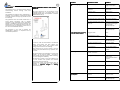
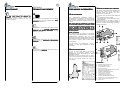
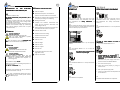
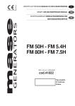
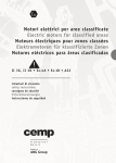
SEMISOM /80
ELECTRIC SUBMERSIBLE
PUMPS
for sewage water
USER’S AND
INSTALLATION MANUAL
“Translation of the Original
Instructions”
Via G. Di Vittorio, 9
61034 Fossombrone (PU) - Italy
Tel. +39 0721 716590
Fax +39 0721 716518
www.bbc.it
[email protected]
Via G. Di Vittorio, 9
61034 Fossombrone (PU) - Italy
Tel. +39 0721 716590
Fax +39 0721 716518
www.bbc.it
[email protected]
1
PLATE DATA
IT - Costruttore e luogo di archiviazione del fascicolo tecnico:
GB - Manufacturer and place where all technical records are filed:
FR - Constructer et place ou tout le dossier technique est déposé:
DE - Hersteller und Ort der Aufbewahrung der technischen Unterlagen:
ES - Fabricante y el lugar donde todos los expedientes técnicos se presentan:
MANUAL UPDATING
DIAGRAM
BBC Elettropompe Srl - 61034 Fossombrone (PU) – ITALY
Tel. +39-0721-716590 - Fax +39-0721-716518 - www.bbc.it
Code/Description
L08/ 6th RELEASE
IT - DICHIARAZIONE CE DI CONFORMITA':
Prodotti:
Prodotti elettropompe serie SEMISOM …./80 (vedi elenco a pagina 12)
Dichiariamo che i prodotti sopraelencati sono conformi alle seguenti Direttive:
- MACCHINE 2006/42/CE;
- BASSA TENSIONE 2006/95/CE;
- COMPATIBILITA' ELETTROMAGNETICA 2004/108/CE
ed alle seguenti norme armonizzate:
- SICUREZZA DEL MACCHINARIO UNI EN ISO 12100
GB - CE STATEMENT OF CONFORMITY:
Products:
Products electric pumps series SEMISOM …./80 (see the list on page 12)
We declare that the products listed above comply with the following Directives:
- MACHINERY 2006/42/EC;
- LOW VOLTAGE 2006/95/EC;
- ELETROMAGNETIC COMPATIBILITY 2004/108/EC.
and to the following harmonised standards:
- SAFETY OF MACHINERY UNI EN ISO 12100
FR - DECLARATION CE DE CONFORMITE:
Produits:
Produits electropompes serie SEMISOM …./80 (voir la list à la page 12)
Nous déclarons que les produits énumérès ci-dessus sont conformes aux Directives suivantes:
- MACHINES 2006/42/CE;
- BASSE TENSION 2006/95/CE;
- COMPATIBILITE ELECTROMAGNETIQUE 2004/108/CE.
et aux norme harmonisées suivantes:
- SÉCURITÉ DES MACHINES UNI EN ISO 12100
DE - KONFORMITÄTSERKLÄRUNG CE:
Produkte:
Produkte Elektropumpen Serie SEMISOM …./80 (siehe Liste auf Seite 12)
Wir, den hier unterzeichnende, daß die vorgenannten Produkte entsprechen folgenden Richtlinien:
- MASCHINENRICHTLINIE 2006/42/EG;
- NIEDERSPANNUNGSRICHTLINIE 2006/95/EG;
- RICHTLINIEN DER ELEKTROMAGNETISCHEN KOMPATIBILITAT 2004/108/EG.
und den folgenden harmonisierten Normen:
- SICHERHEIT VON MASCHINEN UNI EN ISO 12100
ES - DECLARACION CE DE CONFORMIDAD:
Productos:
Productos electrobombas serie SEMISOM …./80 (véase la lista en la página 12)
Declaramos que los productos arriba indicados se hallan conformes a las Directivas siguientes:
- MAQUINAS 2006/42/CE;
- BAJA TENSION 2006/95/CE;
- COMPATIBILIDAD ELECTROMAGNETICA 2004/108/CE.
y a las normas armonizadas siguientes:
- SEGURIDAD DE LAS MÁQUINAS UNI EN ISO 12100
TABLE OF CONTENTS
Secti
on
N° of
revision
06
Date
Jul. 2014
L08/ 5th RELEASE
05
Feb. 2012
L08/ 4th RELEASE
04
Sept. 2010
WARRANTY
4
SOME REMARKS ABOUT THE
USER’S MANUAL
4
PRELIMINARY INFORMATION
- LETTER ON DELIVERY
- MACHINE IDENTIFICATION
- GENERAL INFO AT DELIVERY
- DESCRIPTION OF THE SEMISOM/80
ELECTRIC SUBMERSIBLE PUMP
L08/ 3rd RELEASE
03
May 2010
L08/ 2nd RELEASE
02
August 2006
L08/ 1st RELEASE
01
March 2006
- USE (PURPOSE — SPECIFIC USE)
- IMPROPER USE
- PLACE OF USE
- MAIN PARTS OF THE ELECTRIC PUMP
SAFETY INSTRUCTIONS
- MAIN SYMBOLS AND THEIR
-
1
1.1
1.2
1.3
5
5
5
5
1.4
1.4.1
1.4.2
1.4.3
1.4.4
6
6
6
6
6
2
8
8
9
MEANING
CONTENT
TECHNICAL FEATURES
3
12
HANDLING, INSTALLATION AND
CONNECTION
- PRELIMINARY INFORMATION ABOUT
4
14
4.1
14
4.2
15
4.2.7
4.3
16
18
4.4
21
START
5
23
STOPPING AND CLEANING
6
23
MAINTENANCE
7
24
TROUBLES AND CLEANING
8
24
-
INSTALLATION AND CONNECTION
INSTALLATION WITHOUT DESCENT
AND ANCHORAGE DEVICE
(OPTIONAL)
CHECK OF THE SENSE OF ROTATION
INSTALLATION WITH DESCENT AND
ANCHORAGE DEVICE(OPTIONAL)
ELECTRIC CONNECTION
CE DECLARATION OF
CONFORMITY
Fossombrone, 08/07/2014
Page
26
Il Legale Rappresentante
Mario Cecchini
Via G. Di Vittorio, 9
61034 Fossombrone (PU) - Italy
Tel. +39 0721 716590
Fax +39 0721 716518
26
3
WARRANTY
The products have a 24 months warranty against
manufacturing defects starting from their
installation.
The guarantee is limited to either replacement or
repairing, at our workshop, of defective products
or pieces and does not imply any possible request
for indemnity.
TROUBLE
POSSIBLE CAUSE
REMEDY
1) The electric pump does not
start
No power supply
Make sure that there is
voltage in the mains
Intervention of the thermal
protection
See point 3) Thermal protection
intervention
Burnt-out fuses
Replace fuses
Cut-off of one phase
Restore the phases
SOME REMARKS ABOUT THE USER’S
MANUAL
The User’s Manual is not one accessory of the
ELECTRIC PUMP, but it is integral part of the
ELECTRIC PUMP itself and represents a SAFETY
MEASURE (EN 292/1).
The thermal trip has switched the Wait until temperature
pump off
falls down
The guarantee does not include troubles due to
wrong electric connection, lack of suitable
protection, faulty assembling, wrong operations,
defects of installation, any kind of corrosion and
abrasion due to the pumped liquid as well as nonobservance of the use provided for (point 1.4.1) in
the User’s and installation Manual.
The guarantee is not valid if products are
disassembled, repaired or tampered with by
unauthorized personnel.
2) The electric pump is running
but its flow rate is reduced
In order to make the consultation of the Manual
easier, each subject has been divided into
numbered points, which, when required while
acting, are shown also on the drawings.
This manual has to be kept properly, near the
electric pump and delivered to any operator, user
or owner.
The water detection probe in the
first chamber has switched the
pump off
Restart the control device.
If the device stops again,
please contact
BBC Elettropompe
The power cable is damaged
Please contact
BBC Elettropompe
Clogged suction
Clean
Clogged pipes or valves
Clean
Impeller excessively worn out
Please contact
BBC Elettropompe
The sense of rotation of the
impeller is inverted
Invert two phases
Low liquid level
Turn the Mains Switch
on “0” and let the liquid
level up
3) Thermal protection intervention The sense of rotation of the
impeller is inverted
The manual shall not be damaged; it must be kept
integral – do not tear any sheets –, be kept far
from humidity and heat sources. While consulting,
try not to damage its readability.
The sections to which to pay most attention are
put into evidence with symbols and detailed
illustrations above the pictures.
Giving these notices, the Manufacturer aims at
drawing – in unequivocal way – the operator’s
attention to measures,
measures dangers and warning
related to him/her.
Wrong power supply parameters
Supply the electric pump with the
power supply
parameters indicated on
the plate
Cut-off of one phase
Restore the phase
Clogged impeller
Clean
Wrong calibration
Carry out a new calibration
4) The intervention of the thermal Motor out from the liquid to be
trip is frequent
pumped
Broken thermal trip
4
Invert two phases
Increase the liquid level
inside the basin
Please contact
BBC Elettropompe
25
SECTION 7
MAINTENANCE
As for any maintenance, repairing and cleaning
(that FOR LONG STOPS OR PERIODS OF
IDLENESS excepted), please contact BBC
Elettropompe which will provide you with all
relevant instructions.
SECTION 1
PRELIMINARY INFORMATION
SECTION 8
TROUBLES AND REMEDY
1.1
LETTER ON DELIVERY
8.1
Read this user’s and installation manual carefully
and, particularly, read and understand the “Safety
Safety
Instructions”
Instructions of Section 2 .
8.2
The operations marked with this symbol must be
carried out by an ELECTRIC MAINTENANCE
OPERATOR OR TRAINED PERSONNEL (see EN
60204-1, point 3.52).
8.3
The operations marked with this symbol must be
carried out by a MECHANICAL MAINTENANCE
OPERATOR.
OPERATOR
The SEMISOM/80 ELECTRIC PUMP is
manufactured in compliance with the Directives
2006/42/CE; 2006/95/CE and 2004/108/CE
and with the harmonised standards UNI EN ISO
12100
BBC informs that any modifications or tampering
to the ELECTRIC PUMP and/or operations carried
out in nonnon-compliance with the provisions of this
manual, especially the nonnon-observance of the
Safety Regulations, imply the nonnon-validity of the
Warranty and make the EC Declaration of original
Conformity invalid.
The electric submersible pumps Semisom/80, as
well as their pieces and/or accessories, are
delivered inside one wooden box and one
cardboard box (accessories).
In any case, when you receive them, always check
that:
- the packaging must be integral;
- the electric pump and its accessories have not
been damaged.
Should there be any damage or missing parts,
inform the supplier, the forwarding agent or his
insurance company immediately, providing him
detailed information.
g
f
Please, remind that:
The technical data are referred to the electric
pump Semisom/80 (SEE SECTION 3 – TECHNICAL
PARTICULARS); drawings and any other
documents are owned by BBC which reserves all
the relevant rights and the same can not be put at
third parties’ disposal without BBC written
authorization.
For this reason, any reproduction – even if
partially – of text and illustrations is strictly
prohibited.
8.4
The operations marked with this symbol can be
carried out by an OPERATOR.
OPERATOR
1.3
GENERAL INFORMATION AT DELIVERY
1.2
MACHINE IDENTIFICATION
In case of contact with BBC or its customer
service, as to subjects related to the
SEMISOM/80 electric submersible pump, always
mention the model.
Transcribe the type of electric pump, so that a
copy of the manual can be requested, should this
one be lost and/or should the label be
unreadable.
a
m
e
d
c
b
l
h
k
n
j
i
DESCRIPTION
a
b
c
d
e
f
g
h
i
j
k
l
m
n
24
- SEMISOM /80 ELECTRIC PUMP
- ELECTRIC PUMP SUPPORT
- FLANGE DN 80 (OPTIONAL)
- GASKET (OPTIONAL)
- BOLTS AND WASHERS TE M16X70 (OPTIONAL)
- BEARING BASE (OPTIONAL)
- SCREWS TE M16X25 (OPTIONAL)
- COUPLING FOOT (OPTIONAL)
- TUBE SUPPORT (OPTIONAL)
- CONNECTION CLAW (OPTIONAL)
- SCREWS TCEI M10X30 (OPTIONAL)
- INSERTS FOR FOOT AND SUPPORT (OPTIONAL)
- USER’S MANUAL AND INSTALLATION
- PLATE DATA
5
1.4
DESCRIPTION OF THE ELECTRIC
SUBMERSIBLE PUMP SEMISOM /80
1.4.1
USE
(PURPOSE - SPECIFIC USE)
The electric submersible pump Semisom /80 is
designed for:
- collection of sewage water and mud, conveying
of drainage water, waste water, sewage water
and sewage of septic tanks
- pumping of liquids containing filamentous solid
matters and activated sludge (by maintaining
their relevant biologic process with a 4-pole
1400 RPM motor).
1.4.2
IMPROPER USE
CAUTION DANGER OF
FIRE AND TOXICITY!
THE ELECTRIC PUMP MUST NOT BE
USED TO PUMP DANGEROUS LIQUIDS
(either inflammable or toxic).
Any other use different from the PROVIDED USE
FOR has to be considered as improper use.
1.4.3
PLACE OF USE
CAUTION DANGER
OF EXPLOSION!
THE ELECTRIC PUMP MUST NOT BE
INSTALLED IN EXPLOSIVE PLACES.
CAUTION DANGER
OF ELECTROCONDUCTION!
THE ELECTRIC PUMP MUST NOT BE
INSTALLED IN PLACES WHERE THERE ARE
PEOPLE IN CONTACT WITH LIQUIDS (i.e.
swimming-pools).
1.4.4
MAIN PARTS OF THE ELECTRIC PUMP
SECTION 5
STARTSTART-UP
SECTION 6
STOPPING AND CLEANING
5.1
The operator must have read this user’s and
installation manual and, particularly, well read
and understood the “Safety
Safety Instructions”
Instructions of
Section 2 .
6.1
The operator must have read this user’s and
installation manual and, particularly, well read
and understood the “Safety Instructions” of
Section 2.
5.2
Before starting the electric pump, make sure that
there is liquid to be pumped inside the basin and
that the electric pump is submersed.
6.2
Turn the MAINS SWITCH on “0” to stop the electric
pump.
A - Cast iron impeller
B - Water detection probe: it indicates the
presence of water inside the first chamber
C - Thermal trip: it detects the temperature of the
motor heat preventing its overheating
D - Bearing 3206 ATN9
E - Graphite and ceramics
mechanical seal
inside the first chamber (lubricated with
Castrol Magna 68 oil).
F
- Silicon carbide and ceramics mechanical seal
In contact with the liquid to be pumped
G - Stainless steel tie-rods
H - Stainless steel motor casing
I - Stainless steel motor shaft
J - Stainless steel handle
K - Cast iron cover
L - Cast iron flange
M - Cast iron volute
N - Cast iron support
O - Cast iron foot
P - Cooling liquid asynchronous motor
OK
5.3
Make sure that either basin or pit are properly
closed.
5.4
Turn the MAINS SWITCH on “1” to start the
electric pump.
0
6.3
IN CASE OF LONG PERIODS OF STOP IT IS
NECESSARY :
a - to turn the MAINS SWITCH on “0”
0
The electric pump is started and the
extraction of liquid begins.
(Agip Acer 15 Oil )
Q - Cast iron seal-holder
1
Max. installation depth 20 mt.
5.5
Turn the MAINS SWITCH on “0” to stop the electric
pump.
Minimum and maximum operating temperature of
the pumped liquid:
- 0 / 50°C for continuous duty.
b - CAUTIONCAUTION-DANGER OF ELECTRIC
SHOCK! This operation shall be
carried out by an ELECTRIC MAINTENANCE
OPERATOR
Disconnect the power supply cable from the
terminal board of the MAINS SWITCH
c - Pull out the electric pump
d - Clean all its parts properly, by using a hotwater cleaner
The electric pump Semisom/80 has no vibrations
and its noise is below 70 db (A).
0
e - Roll up the power supply cable
f - Store it in a place where the temperature does
not fall below 0° .
In case of applications different from those
provided for in this manual, please contact
BBC Elettropompe.
5.6
The START-UP is completed.
6
6.4
STOPPING AND CLEANING are completed.
23
Make ABSOLUTELY
JOINTS .
WATER-PROOF
4.4.11
CONNECTION DIAGRAM
4.4.10
CONNECTION
0
J
Turn the MAINS SWITCH on
“0” (zero).
The electric pump SEMISOM/80 is supplied with a
seven-wire power supply cable .
The yellow/green wire has to be connected to the
earthling system and must be longer than the
power wires.
wires In case of tearing, it will be the last
wire to be disconnect.
PE
YELLOW/
GREEN
Earth wire
U
V
W
BLUE
BROWN
BLACK
Power wires
T1 - T2
WHITE
S1
GREEN
The (blue - brown - black) power wires:
- have a 2,5 mm² section
- must be protected by fuses or magnetic switch
from short circuits and by thermal switch from
motor overload (carry out the thermal protection
calibration according to the motor absorption as
per the plate)
- must be connected to the terminals U – V — W of
the control and protection panel.
The white wires:
- have a of 0,75 mm² section
- are connected to the automatic restart bimetallic
thermal sensor (thermal trip) placed near the
winding
- must be connected in series to the control
contactor coil and open the circuit in case of
motor overheating.
The green wire:
- has a of 0,75 mm² section
- is connected to the probe for water detection
inside the first chamber
- must be connected to the level control device to
be installed inside the non-supplied panel .
K
THERMAL TRIP
To be connected in series
to the coil of the control
contactor.
(Not supplied with
the electric pump).
WATER DETECTION
PROBE IN THE
FIRST CHAMBER
To be connected to level
control device, with
earth common terminal.
(Not supplied with
the electric pump).
C
H
P
D
E
B
Q
F
A
NOTES!
Make sure that the electric cables are in good
state and the terminals are well tightened to
relevant clamps.
Check periodically the correct functioning of
the differential gear by pushing the test key .
A periodic check of the correct functioning of
the electric protections is also recommended.
In case of intervention of one of the
protections, check the reason before
restoring the system.
Install the control and protection devices in
rooms suitable to their IP protection degree.
G
I
N
L
M
O
4.4.12
THE ELECTRIC CONNECTION is finished .
22
7
SECTION 2
SAFETY INSTRUCTION
While consulting this user’s manual you will find
some symbols that have a precise meaning.
CONVENTIONAL SYMBOLS
AND THEIR DEFINITION
CAUTION! DANGER OF ELECTROCUTION!
It indicates to the concerned personnel that the
described operation presents risk of electric shock
if it is not carried out in compliance with the safety
regulations.
CAUTION! GENERAL DANGER!
It indicates to the concerned personnel that the
described operation presents risk of physical
injury SPECIFIED IN TEXT AND SYMBOLS,
SYMBOLS if it is
not carried out in compliance with the safety
regulations.
NOTE!
It indicates to the concerned personnel
information whose subject is to be taken into
particular consideration or is important.
WARNING!
It indicates to the concerned personnel
information whose subjects, if not observed, may
provoke slight injury to persons or damage to the
machine.
4.4
ELECTRIC CONNECTION
MECHANICAL MAINTENANCE OPERATOR
Qualified technician able to manage the machine
in normal conditions and able to operate on the
mechanical parts in so to carry out all
adjustments, maintenance interventions and
repairs required .
He/she is not qualified to operate on electric
systems with voltage presence.
4.4.1
CAUTION!
During the operations of electric connection, the
DANGER OF ELECTRIC SHOCK is present. For this
reason the operation will have to be carried out
only by trained personnel (see EN 60204.1 point
3.52).
ELECTRIC MAINTENANCE OPERATOR OR TRAINED
PERSON (see EN 6020460204-1 point 3.52)
Qualified technician able to operate the machine
in normal conditions. He/she is put in charge of
the interventions of electric adjustment,
maintenance and repairing.
He/she is able to operate with voltage presence
inside electric panels or control boxes.
4.4.2
Make sure that the system is equipped with
proper EARTHLING.
4.4.3
Make sure that the system is equipped with
differential switch and check the correct running
by pushing the test key. The differential current of
nominal running shall not exceed 30 mA.
PERSONAL PROTECTION
The operator is OBLIGED to use devices for
personal protection in presence of one of these
symbols is present.
4.4.4
Check that both voltage and mains frequency
correspond to the PLATE data.
RECOMMENDATION
It is referred to a method of work experienced at
the factory, keeping in mind that each operator
will develop his/her own way to operate.
Fluctuation of the mains voltage is allowed,
provided that this does not exceed ± 10% the
nominal value.
SPECIAL INTERVENTIONS
Any special maintenance interventions
evidenced by this symbol are to be
requested to BBC Elettropompe.
NOTE!
The direct connection of the electric pump to
the power mains by plug is absolutely
prohibited. A control and protection panel has to
be installed near the pumping station.
4.4.7
Have the connection diagram at your disposal
(see 4.4.11)
4.4.8
ELECTRIC PANEL
As for the safe functioning of the electric pump,
the electric panel shall be workmanlike
performed, equipped with documentation and
certificate of conformity with the regulations in
force within the Country of installation.
It has to be made reminding to protect the electric
pump from:
• Overload
Always install thermal relay to protect the motor
and set. It considering the plate nominal current ;
• Over temperature
The electric pump is equipped with an automatic
restarting thermal trip to be connected in series to
the coil of the contactor. It is fixed near the
winding and breaks continuity in case of motor
overheating ;
• Water infiltration
The electric pump has a probe which detects
presence of water in the first chamber that must
be connected to a level control by means of
common earth terminal;
• Dry running
Protect the electric pump with level control
devices (ex. float switches, electrodes). The
control circuit must be a low-voltage one .
4.4.9
POWER SUPPLY CABLE
THE CABLE OF THE ELECTRIC PUMP IS 10
METRES LONG. IF THE LINE IS OVER 10 METRES
DISTANT SEE THE TABLE OF THE BBC GENERAL
CATALOGUE “CABLE CHOICE” .
NOTES!
Bigger fluctuations might damage the regular
running of the machine.
OPERATOR
Identifies qualified personnel, that is to say with
the specific skills required for manual operations.
4.4.5
Make sure that the power supply system is
dimensioned to stand the machine power.
4.4.6
Make sure that the system is equipped with a
proper thermal-magnetic over current circuit
breaker with adequate braking power.
The operator is absolutely prohibited to carry out
operations reserved to the ELECTRIC OR
MECHANICAL MAINTENANCE OPERATOR.
OPERATOR
8
21
4.3.18
Screw the supplied screws in the connection
bracket of the electric pump and TIGHTEN.
4.3.21
Bring the Power Supply Cable out from the basin;
basin
fix it firmly with clamps, fairleads, etc., so that it
does not get to the basin bottom and close to the
suction of the electric pump .
CONTENT
2.1
Before installing the electric pump, the customer
shall make sure that the floor on which the
machine will be installed is sufficiently levelled
and can stand its weight (see Technical
Particulars Section 3).
3 Furthermore, he/she will
verify the presence of technological devices and
sufficient room on all sides for any possible
maintenance.
2.2
Before the installation, the user shall be obliged to
verify that the supply mains to which the electric
pump will be connected, actually corresponds to
the voltage on the plate (see Technical Features
Section 3).
3 The user shall also be obliged to check
that the mains is also equipped with a suitable
earthling. In case it is not, adapt the system.
2.3
As far as the connection is concerned, follow the
laws of the Country where the electric pump will
be installed.
4.3.19
Position the electric pump close to the pipe
support.
support
2.4
Upstream the machine, on the electric supply line,
a differential magnetic-thermal safety switch shall
be installed (operation to be charged to the
operator) in order to interrupt all phases. (As for
dimensioning see Technical Particulars Section 3).
3
4.3.22
NOTE!
As for the next lifting of the electric pump,
leave the safety hook with relevant rope or chain
hooked to the handle of the electric pump.
4.3.20
By keeping the electric pump hooked, let it gently
down along the pipes to the automatic anchorage
with the connection foot.
4.3.23
THE INSTALLATION OF THE ELECTRIC PUMP WITH
DESCENT AND ANCHORAGE DEVICE is finished.
20
2.5
The personnel chosen for the handling of the
electric pump and its accessories will have to
wear gloves and accident prevention shoes.
2.6
As for the handling operations of the unpacked
machine, See Section 4 - Handling, Installation
and Connection.
2.7
UNEXPERIENCED PERSONS MUST NOT USE THE
ELECTRIC PUMP SEMISOM/80 .
2.8
In case of trouble, immediately turn the General
Switch of the Mains on “0” (zero
zero).
zero
“0”
2.9
The operation of servicing, maintenance, repairing
of the electric pump shall be carried out only by
QUALIFIED ELECTRIC MAINTENANCE OPERATOR
OR MECHANICAL MAINTENANCE OPERATOR who
knows both safety instructions and content of this
manual.
2.10
ZERO POWER STATE
Prior of carrying out any interventions on the
electric pump, switch it on 0 ”ZERO”.
”ZERO”
- Turn the GENERAL SWITCH on “0”
- Remove fuses (if present).
- Indicate “WORK IN PROGRESS” by putting a
panel on mains switch.
THE ELECTRIC PUMP IS EQUIPPED WITH
RESWTHICING DEVICES WHICH MAY
PROVOKE ITS AUTOMATIC RESTARTING!
2.11
The personnel prepared to operate on the electric
pump shall have the following IPD (Individual
Individual
Protection Devices)
Devices at disposal:
helmet, protection glasses, oxygen set, safety
sling, gloves, accident prevention shoes, which
shall be used when required.
The same personnel shall also:
♦ Wear work overalls with closed cuffs
♦ Tie hair if this is long
♦ Never wear fluttering and/or torn objects and/or
clothing (i.e., necklaces, watches, rings,
bracelets, scarves, neckerchiefs, ties, etc.).
9
2.12
CAUTION! DANGER OF INFECTIONS!
Before carrying out any interventions on the
electric pump, the personnel operating shall make
sure to use all the hygiene and health measures;
clean the electric pump Semisom/80 accurately
using a hot waterwater-cleaner.
2.16
Start the electric pump only when this is
completely well-fixed and permanently installed.
NEVER START IT WITHOUT LIQUID.
4.3.9
Let the connection foot gently down into the place
of installation.
4.3.13
Position the pipes inside the housing of the
connection foot and housing of the pipe support.
support
4.3.14
Tighten the screws of the pipe support.
support
OK
NO
4.3.15
NOTE!
If the pipes are over 4 metres long, position
the median bracket/s for support.
2.13
NOTE!
Do not move and do not handle the electric
pump by using its cable.
4.3.16
Introduce the safety hook into the handle of the
electric pump and make sure that the safety lock
is in a correct position.
.
2.17
CAUTION! DANGER OF ELECTROCUTION!
The electric pump Semisom/80 MUST NOT be
used NOR started if somebody is in contact with
the liquid to be pumped.
2.14
CAUTION! DANGER OF
SHEARING, CUTTING AND ABRASION!
Do not put hands nor any objects near the
impeller, that is to say at the inlet or outlet
openings of the electric pump.
4.3.10
Release the safety hook.
hook
4.3.11
Two persons will position the connection foot so
that the pipes will be perpendicular to the pipe
support..
support.
4.3.11
2.15
The electric pump Semisom /80 can work only
in vertical position.
position
(Motor up and pump section down).
OK
2.18
IT IS FORBIDDEN TO CARRY OUT IMPROVISED
REPAIRINGS JUST TO START WORKING IN ANY
CASE.
2.19
Make sure that there are no tools, rags and other
material left inside the electric pump or where it is
installed.
4.3.11
4.3.12
4.3.12
Mark the points where the holes shall be executed
- Drill the holes
- Introduce the 4 small blocks supplied
- Position the connection foot
- Tighten the screws of the small blocks.
10
4.3.17
NOTE!
At this point it is necessary to verify the sense
of rotation of the impeller.
Execute all the operations described from point
4.2.5 to point 4.2.7 a, b, c, d, e, f, included.
19
4.3
INSTALLATION WITH DESCENT AND
ANCHORAGE DEVICE (optional)
NOTA!
4.3.1
Before beginning the installation, read sections
4.1., 4.3 and 4.4 of this manual.
4.3.5
Decide where to put the pipe support so that the
pipes are perpendicular to the connection foot
which will be positioned later.
2.20
Since the electric pump can reach very high
temperatures, wait until it cools down before
handling it.
100°
80°
60°
60°
20°
4.3.6
2.23
As soon as the machine has finished its life cycle,
do not get rid of it in the environment.
Please contact the firms in charge for Waste
Disposal.
100°
80°
60°
60°
20°
4.3.2
Unscrew the screws at the lowest part of the box
and remove the lid from the base.
4.3.5
2.21
Always use and ask for original spare parts.
4.3.3
Take a means (ex. winch, pulley, etc.) with suitable
capacity and safety hook at its end.
4.3.4
Take a Ø 2 inch pipe of length required for the
sliding of the device.
If the basin is more than 4 metres deep, take
(along with pipes) also some median brackets for
both support and joining of the pipes.
4.3.6
Mark the points where the holes will be executed
- Drill the holes
- Insert the small blocks
- Fix the screws but DO NOT TIGHTEN THEM.
THEM
4.3.7
Introduce the safety hook into the connection foot
and make sure that the safety lock Is in the
correct position.
2.22
The oils contained inside the electric pump are
not soluble in water; for this reason, their disposal
will be carried out following the regulations in
force.
X
4.3.8
KEEP ANYONE AWAY FROM THE PLACE OF
INSTALLATION.
18
11
SECTION 3
TECHNICAL FEATURES
c.
d.
2 pole 50 Hz - VORTEX IMPELLER
P2
P1
ThreeThree-phase 400V - 50 Hz
HP
KW
KW
A max
Cable m.
DNM
Solid passage Ø
SEMISOM 1555/80 T
5,5
4
5,34
9,15
10
80
74
SEMISOM 1255/80 T
5,5
4
5,31
9,1
10
80
74
SEMISOM 1055/80 T
5,5
4
5,41
9,2
10
80
74
SEMISOM 1775/80 T
7,5
5,5
6,8
11,9
10
80
74
SEMISOM 1675/80 T
7,5
5,5
7
12
10
80
74
SEMISOM 1375/80 T
7,5
5,5
6,8
11,9
10
80
74
SEMISOM 2100/80 T
10
7,5
9
16,2
10
80
74
SEMISOM 1600/80 T
10
7,5
9
16,2
10
80
74
SEMISOM 1200/80 T
10
7,5
9,1
16,4
10
80
74
Turn the MAINS SWITCH on “1” for 1 (one)
second,
second then reposition it on “0” zero.
Check the RECOIL of the electric pump. IT
MUST BE OPPOSITE TO THE SENSE OF THE
ARROW
1”
0
4.2.8
Paying attention to the electric cable, gently let
the electric pump down until it reaches the place
of installation.
4.2.9
Operation to executed by two persons!
Release the safety hook and position the electric
pump close to the system flange.
4.2.10
Position the gasket between the two flanges.
1
4.2.12
Flow rate
m³/h
0
12
24
30
36
48
60
l/m
0
200
400
500
600
800
72
78
90
96
108
114
123
1000 1200 1300 1500 1600 1800 1900 2050
Total manometric head in meters
1555/80 T
1255/80 T
14
13,6
13
12,6 12,1 10,6
8,2
6,3
15,5 14,8 14,1 13,7 13,2 11,9
9,7
7,7
5,5
4
4.2.9
1055/80 T
17
16,5 15,9 15,5 15,1 13,7
11,4
1775/80 T
17
16,5 15,9 15,5 15,1 13,7
11,4
9,1
8,1
6,5
5,7
1675/80 T
19
18,3 17,6 17,2 16,8 15,6
13,7
11,1
9,9
8,1
7,4
1375/80 T
21
20,1
19
18,5
18
16,8
15
12,7
11,6
2100/80 T
21
20,1
19
18,5
18
16,8
15
12,7
11,6
9,6
8.7
1600/80 T
24
23,2 22,3 21,7 21,3 19,9
18,3
16,1
14,9
12,6
1200/80 T
27
25,7 24,4 23,8 23,2
20,4
18
22
4,4
6,7
5,7
4
♦
If the SENSE OF ROTATION is correct,
proceed as follows.
4.2.10
2 pole 50 Hz - DOUBLE CHANNEL IMPELLER
P2
P1
ThreeThree-phase 400V - 50 Hz
HP
KW
SEMISOM 2700/80 T
11
8
KW
Portata
10,4
A max
Cable m.
DNM
Solid passage Ø
18
10
80
45x62
If the SENSE OF ROTATION is not correct, it is
nec essary
FOR THE ELECTRIC
MAINTENANCE OPERATOR to invert two poles
at the terminal board of the MAINS SWITCH.
Afterwards, repeat the operations at
4.2.7 a, b, c, d.
d
4.2.11
Introduce the bolts into the holes and screw in the
nuts. Tighten all nuts well.
NOTE!
A wrong SENSE OF ROTATION provokes reduction
of flow rate, rise in absorption and damages to the
electric pump.
4.2.12
Let the Power Supply Cable out from the basin; fix
it firmly with clamps, fairleads, etc., so that it will
not get to the basin bottom and close to the
suction of the electric pump .
♦
Flow rate
m³/h
0
30
45
60
72
78
90
l/m
0
500
750
1000
1200
1300
96
1500 1600
108
123
135
150
165
1800
2050
2250
2500
2750
12,1
10,4
8,7
6,5
4
4.2.11
Total manometric head in meters
2700/80 T
20
18,5
17
15,8
15,3
14
13,4
4 pole 50 Hz - VORTEX IMPELLER
P2
P1
ThreeThree-phase 400V - 50 Hz
HP
KW
SEMISOM 1504/80 T
3,5
2,6
KW
Portata
3,64
A max
Cable m.
DNM
Solid passage Ø
8,15
10
80
74
Flow rate
m³/h
0
12
24
30
36
48
l/m
0
200
400
500
600
800
60
66
72
78
84
90
e.
1000 1100 1200 1300 1400 1500
Total manometric head in meters
1504/80 T
9,7
9,3
8,8
8,6
8,3
7,6
6,8
6,3
5,8
f.
5,4
4,9
P1 = Maximum power absorbed by the mains P2 = Nominal power of the motor
4,4
12
Disconnect the electric pump from the
terminal boards of the MAINS SWITCH.
SWITCH
The check OF THE SENSE OF ROTATION is
finished.
4.2.13
THE INSTALLATION OF THE ELECTRIC PUMP
WITHOUT DESCENT AND ANCHORAGE DEVICE is
finished.
17
4.2.4
Introduce the safety hook into the handle of the
electric pump and make sure that the safety lock
is in its proper position.
4.2.6
BEFORE STARTING THE OPERATION DESCRIBED
AT 4.2.7, IT IS NECESSARY TO EXECUTE THE
ELECTRIC CONNECTION AS DESCRIBED IN 4.4
“ELECTRIC CONNECTION”.
DIMENSIONS
TYPE
WEIGHT
A
B
C
D
Kg
SEMISOM 1555/80 T
703
78
383
295
65,5
SEMISOM 1255/80 T
703
78
383
295
65,5
SEMISOM 1055/80 T
703
78
383
295
65,5
SEMISOM 1775/80 T
733
78
383
295
69,0
SEMISOM 1675/80 T
733
78
383
295
69,0
SEMISOM 1375/80 T
733
78
383
295
69,0
SEMISOM 2100/80 T
758
78
383
295
71,0
SEMISOM 1600/80 T
758
78
383
295
71,0
SEMISOM 1200/80 T
758
78
383
295
71,0
SEMISOM 2700/80 T
758
78
383
295
71,0
SEMISOM 1504/80 T
758
78
383
295
71,0
DN80
160
4.2.7
CHECK OF THE SENSE OF ROTATION
a.
b.
127
780
KEEP ANYONE AWAY FROM THE PLACE OF
INSTALLATION;
INSTALLATION
Gently position the electric pump in vertical
position and lift it 5-10 centimetre from the
grounds.
250
4.2.5
It is now necessary to check the sense of rotation
of the impeller.
The correct sense of rotation is printed on the
label.
A
DN80
5/10 cm.
B
D
C
16
13
SECTION 4
HANDLING, INSTALLATION
AND CONNECTION
Before starting the handling, installation
and connection, read carefully the Safety
Instructions at Section 2 and the Technical
Features at Section 3 of this manual.
4.1
PRELIMINARY
HANDLING,
CONNECTION
4.1.4
CAUTION! DANGER OF INTOXICATION OR
POISONING DUE TO TOXIC GAS!
Before installing the electric pump, make sure
that there is neither toxic nor inflammable gas.
4.1.5
CAUTION! DANGER OF SLIPPING!
Before installing the electric pump, make sure
that there is no mud in the place of installation.
4.1.10
It is advisable to install a NON-RETURN valve at
least at 1 (one) metre from the delivery outlet to
avoid a possible flow-back of liquid through the
delivery pipe.
4.1.11
Make sure that the electric pump to be installed is
suitable for the system (see piping Ø, flow of the
electric pump, pipe length, etc.).
You can also consult the table of BBC General
catalogue “pressure loss”.
4.2
INSTALLATION WITHOUT DESCENT AND
ANCHORAGE DEVICE (optional)
4.2.1
Unscrew all screws at the lowest part of the box
and remove the lid from the base.
INFORMATION ABOUT,
INSTALLATION AND
4.1.1
CAUTION! DANGER OF CRUSH, SHOCK AND
ABRASION!
The personnel operating while handling and
installing the electric pump shall wear gloves,
accident prevention shoes and helmet.
4.1.2
Position the electric pump (and relevant
accessories) near the place of installation by
means of lifting equipment, fork lift or hand pallet
truck.
4.1.6
NOTE!
The connection to the system shall be executed
with a DN80 flange.
4.2.2
Screw in the 3 supports to the volute of the
electric pump or the BEARING BASE (optional)
with the screws TE M16x25.
4.1.7
NOTE!
The electric pump Semisom/80 can convey
liquids having a maximum volumetric mass
equal to 1,1 kg/dm3.
4.1.8
Make sure to have sufficient room in the place
where electric pump will be installed.
4.1.9
Enclose the installation area with suitable
barriers.
NOTE!
4.1.12
4.1.3
While installing the electric pump, NEVER work
alone, use safety belts and individual protection
devices (IPD
IPD).
IPD
Before the installation, read all the paragraphs
(4.2, 4.3 and 4.4) so as to be ready to any need.
4.1.13
The preliminary information concerning
HANDLING, INSTALLATION AND CONNECTION are
finished.
14
4.2.3
Use any device (ex. hoist, pulley, etc.) with suitable
capacity and safety hook at its end.
15