1
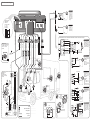
MO UNTI NG S UG G E S TI O NS
Cod. 10035016
INSTALLATION GUIDE
Reserved to qualified personnell.
WA R N I N G !
The manufacturer disclaims any responsibility and does not grant the warranty for faults or malfunctioning
resulting from bad installations or stress beyond the technical characteristics of the devices or missing
installation of the required protection fuses. Do not expose the device to direct water jets: protect it when
washing the engine; consult FIGURE 1 for its assembly. Warranty claims due to water infiltration have to
be demonstrated not resulting from bad installation. Due to alarm exclusive dissuasive function against
possible theft, T.E.K. s.r.l. disclaims any responsabilities for damages caused by theft or theft attempt on
the car or on objects inside it.T.E.K. s.r.l. reserves the right to execute adjustments whenever needed without
prior notice. For a correct functioning of the system it is important to periodically verify the efficiency of the
alarm's sensor
Produced by
No. 1
engine block
Original power
doors
Ultrasonic
capsules
LED display
with key socket
Car key
Push buttons for opening
the trunk and/or hood
Disarming
(doors open)
Via Atto Vannucci sn
51031 Agliana (PT)
Tel. +39.0574.67441
Fax. +39.0574674444
e-mail:[email protected]
web:www.sikura.net
Figure 1
Figure 2 - Installation by means of sticker
Frame
m
TRANSMITTER TECHNICAL FEATURES
RF power (ERP):
< 100µW
Modulation:
On Off Keying (OOK)
Power supply:
1 Alcaline battery 12V 33mAh
Size 23A
Current consumption:
Max 16 mA
Transmission time:
One second ab
Battery life:
The theoretical battery life is
estimated over two years, supposing a fixed consume of 1µA
and 3000 activations, by the
way considering the high temperature to which the vehicle
could be exposed during garaging we do recommend to
change batteries on a yearly
basis.
Magnet
Transmitter
Relay Reed
means of sticker
Frame
Ma
x1
2m
Transmitter
door/window
Magnet
Fix the transmitter with sticker (it is
recommended the one with glue on
both sides), make sure to put it at the
centre of the magnet. The magnet
may be glued on glass surfaces of
fixed with screw if the frame allows it.
Insert the spacers on the magnet in
way that the max distance from the
magnet reed 12 mm is respected.
Preliminary Indications
AZ20004W is a product dedicated to be installed on campers and roulottes. Its software allows to memorize up to
....................
8 opening sensors (doors, windows and side compartments) and 2 remotes.
....................
Functionning
....................
A
door/window
opening
immediately
provoke
an
alarm
triggering.
Upon
alarm
arming
the
wireless
opening sensors
....................
are always active. The protected area can be occupied, making sure to not open closed frames/fixtures. It is possible
to close open frames without provoking an alarm triggering.
It is possible to leave frames open (for instance to change the air) without provoking alarm, in this case the opened
t is possible to leave frames open (for instance to change the air) without provoking alarm, in this case the opened
frame is obviously NOT PROTECTED. The ultrasonic sensors exclusion (even in case of total or partial protection)
can be effected following the standard procedure, without blocking the wireless opening sensors The wireless opening
sensors triggering is recorded in the alarm memory and signalled upon alarm disarming by two beeps and two LED
flashes repeated per 6 times. The same signalling is provided when the main unit is in the installer mode or in his
immunity period after alarm activation, for an easy functioning test.
Type..........acoustic power ............passage frequency
1 ............low...........
2,2 Hz
2 ............high .........
4,4 Hz
3 ............high .........
2,2 Hz
4 ............low...........
2,2 Hz
REMOTE PANIC*:when the device is armed allows the user to switch the siren on with remote controller being outside
the car (see USER'S MANUAL).
BLEEPS*: this function enables the following acoustic signals:
Arming: ..........................................................2 low tone, long bleeps.
Disarming: .....................................................1 low tone, long bleep.
Alarm memory: ..............................................(only the first 6 cycles) refer to the users manual “Alarm memory”.
ENGINE LOCK OUTPUT/ALARM SIGNAL OUTPUT: This function makes it possible to select the output connected
to the green wire. Proceed as follows: select OFF - to activate the engine lock by connecting the green wire to an
optional relay (using the normally open contact) as shown on the general diagram; select ON - to permit the alarm
signal by connecting the green wire to the auxiliary device (pager, satellite, etc.) with negative inputs (max. 0.25 A).
Under these conditions you can also activate the engine lock by using the normally closed contact on the relay.
Azienda con sistema certificato
ICONS
Blinker
P RO G RA MMI NG
SIREN SOUND*: four siren sounds are available.
Accurately read the vehicle’s handbook and the TEK service manual (specifing how to adapt the product to the vehicle);
and together with this manual identify the wires of the vehicle’s original system, which are necessary for the installation.
The product that you are installing directly interfaces with a preexistent system, therefore:
• Do not interrupt components with absorption exceeding those indicated by the electrical features
of the antitheft system (check the absorption of the interrupted components).
• Pay particularly attention to the engine block (if present) and indicators connections.
• Always weld the connections that interface with the vehicle’s system indicated with “ ” in the diagram.
• The wires for the engine block must be as short as possible.
• The grounding is to be made with faston connectors on the appropriate nodes on the vehicle.
Before starting the connections:
• Disconnect the battery’s negative pole.
• Find the ideal position: in the engine compartment the sirens and inside the car the central unit (see fig. 1).
• Keep it at a maximum distance form heat sources and water jets.
Yellow wire: connect to the locked up positive pole (positive, +15, only present with the ignition turned on).
This mandatory safety connection is used to deny the operation of the antitheft system while the vehicle is
running and to trigger the attempted start sensor. The line is edge sensitive, that is: switching the ignition and
leaving it on will trigger the siren once.
Blue wires: this connection is mandatory for correct operation of the automatic rearming, passive arming and
siren off functions. These lines are edge sensitive that is: opening a door and leaving it opened will trigger
the siren once.
Green wire: optional connection. To install the engine block (relay M4 and switch R9), cut the wire that powers
optional the starting motor and follow the connections provided in the diagram for “engine block” function.
WARNING! Never interrupt the ignition circuit in catalysed cars.
No fuses are provided to protect engine blocking circuits as they are supposed to be already protected in the
original plant. Is therefore mandatory to check that the interrupted circuits are protected by fuses rated for a
current less than or equal to the relais current.
White and purple wires: These are used to command negative input power doors. Choose among the diagrams
A and D, according to the car system, for the connections. You can also activate closing of the windows and/or
sunroof on vehicles provided with the “comfort” system by increasing the activation times of the centralized
locking (see centralized locking times selection).
CAUTION! The unit exclusively controls negative locking.
For installations with universal centralized locking, connect M5 module, choosing among the diagrams B, C, F, G
according to the car system.
ULTRASONIC TRANSMITTERS: place these at the sides of the dashboard so that these are not faced and
turned towards the rear part of the passenger compartment.
LED DISPLAY - ELECTRONIC KEY SOCKET: Apply (see diagram) onto the car window or onto the dashboard
so as to be easily seen from both outside the car and from the driver's seat. Use the adhesive on the flat surface
of the LED support taking care to scrupulously clean the surface onto which it is to be applied.
Pink wire: (negative output) activates the added modules, such as windows and/or sunroof power locking, or
optional drives relays with a maximum current of 0.25A.
Keep the keys out from the car, reconnect the battery.
SELECTIONS AND SENSITIVITY ADJUSTMENT
INSTALLATION MODE: functional test for all the sensor with trigger signalling..
How to enter the Installer mode: the first time connect the siren and the power supply positive.
Later on: disconnect the siren, disconnect the power supply then reconnect the siren and the power supply
Exiting from the INSTALLATION MODE: just press the
TECHNICALS FEATURES OF THE PRODUCTS:
SIGNALLING TABLE
remote control otherwise switch on the dash-board and wait
for 9 LED blinkings.
AZ2003W series central alarm
Alarm cause :
In the event several sensors are tripped simultaneously,
Power supply..................................................... 10 - 15V
presence of key positive ............................1
only
the
one
appertaining
to
the
group
with
the
highest
Absorbed current ..........................................On ...17mA max......................................................................
doors, trunk and/or hood open...................2
priority
is
signaled
(see
SIGNALLING
TABLE).
Off ...12mA
absorption alarm .......................................2
Working temperature......................................... -40° +85° C (centralina)
SENSIVITY ADJUSTMENTS: Access the trimmers
ultrasonic alarm..........................................3
Relay contacts capacity..................................... 5A a 20° C lamp.frecce
compartment place on the central unit and enter installation
mode.
Modules output capacity............................max. ...250mA
Engine block driver output capacity...........max. ...250mA
No. of flashes
ULTRASONIC SENSIVITY: adjust the trimmer to the
Power doors output capacity ....................max. ...250mA
minimum. Close the car doors, leave a front window halfway
Dimensions ...............................................max. ...L.70 A.25 P.75
open and move your hand inside the passenger compartment, simulating an intrusion. Increase the sensitivity by slowly
Weight ............................................................... 88 gr.
turning the ultrasonic trimmer clockwise until obtaining the signaling of the sensor tripping (see SIGNALLING TABLE).
Close the vehicle completely and give little blows to the windows, making sure that the sensitivity is not too high.
AZ2000 series siren
The tripping of the sensors is checked once every two seconds, therefore the signaling could arrive with a
Current absorbed by siren ...................stand by ...1mA max...................................................................
delay of two seconds.
max. ...1.2A
SELECTIONS (centralized locking times, voltage drop and passive arming).
Working temperature:........................................ -40° +125° C (siren)
Dimensions ...............................................max. ...L.74 A.71 P.74
VOLTAGE DROP SELECTION: detects voltage drops caused by turning on lamps exceeding 3 Watt.
Weight ............................................................... 450 gr.
PASSIVE ARMING SELECTION: Automatically arms the device getting off the vehicle.
POWER LOCKING TIME SELECTION: (See FIG. 5 - SELECTIONS in the general connection diagram).
PANIC/ANTI-AGGRESSION: in both armed and disarmed state, with ignition on, allows the user to switch the siren
on with the remote control (see USER'S MANUAL).
AUTOMATIC REARMING: automatically returns to the protection state if no door is opened within 45 seconds after
disarming. Warning: check any cars' compartment where the user could unattendedly put the keys and the remote
controls to be protected by push buttons connected to the blue wire.
ACCESSING PROGRAMMING
WARNING! This product is provided with factory programming that is: SIREN TYPE 3; ALL THE OTHER FUNCTIONS
OFF. These functions marked with “*” shall not be enabled for installation in EEC countries.
1st
rd
3
Get on the car and close the doors.
2nd
With the remote, arm the system.
The LED turns on for 6 sec. while the locking system is actioned, then it turns off.
4th
After the LED has turned off, switch on the dashboard and put the electronic keys in the LED plug, you will hear a
double sound indicating the beginning of the programming. Switch off the dashboard. In case of error disarm the system
with the remote and start all over from step number 2nd.
Actions on
ignition key
5th
6th
7th
8th
9th
10th
11th
12th
LED
flashes
6
5
4
3
2
1
continuous
Programmed
function
Answer to remote control activation
Siren sound *
1,5 sec. of selected siren sound; once the
preferred one is heard go to step 6th.
Remote panic *
Bleep *
Engine lock output
Alarm signal output
Panic / Anti-aggression
Automatic rearming
ON
OFF
ON
OFF
ON
OFF
ON
OFF
ON
OFF
Self-learning
for remotes,
Storing of remote
control
electronic keys and
and sensors
electronic key
radio
End programming
turning ON/OFF ignition key
low tone bleep
high tone bleep
SELF-LEARNING FOR REMOTES, ELECTRONIC KEYS AND RADIO SENSORS: It allows to memorize up to 2 remotes,
2 electronic keys and up to 8 radio sensors excluding eventual lost or not working objects. After having switched on and off
the dashboard to enter the 11th step 3 sounds will be issued (two high and one low): at this point press one of the two remotes
(black casing) enclosed, in order to memorize all the remotes and the sensors, switch on the dashboard and insert the electronic
keys in the plug of the LED, the alarm beeps one time. Switch off the dashboard to exit the programming and memorize the
functions. Go further with the mechanic installation of the sensors following the instructions of the picture number 2
CONDITION MEMORY: the device records all the programmed functions and the functioning state (armed/disarmed) in a
special memory which is not cancelled in case of missing power supply. This function allows to restore the correct functioning
mode at power on, even in those models not equipped with back-up battery.
General connection diagram
DIAGRAM A :
White
For vehicles
provided with
negative
controls of the
power locking
and provided
with comfort
window power
locking.
OPEN
APRE
Comfort
closing
Violet
CLOSE
CHIUDE
DETAIL OF SIREN
CONNECTION
Wires colour:
BB = Brown-Black
R = Red
BL = Blue
BK = Black
DIAGRAM D :
For vehicles
provided with
n e g a t i v e
controls of the
power locking.
OPEN
APRE
R BK
CLOSE
CHIUDE
Cavo alla sirena
BB BL
DIAGRAM B :
White - Black
optional
optional
OPEN
White
Red
White
Violet
Blue
Black
Red
Yelow
Orange
Black
Red
Green
Orange
White
Pink
DIAGRAM FOR
OPTIONAL “WINDOWS
CLOSING” FUNCTION:
module M1; M2; M3;
M3BMW.
DIAGRAM FOR OPTIONAL “UNIVERSAL CENTRALIZED LOCKING” FUNCTION NO. 2 relays M4.
M5 Module
Purple - Black
Red
Max. 5A
Max. 2A
CLOSE
Purple
Light blue
Purple - Red
Red
Max. 10A
For vehicles provided
with central door
locking but not with
driver’s side door actuators or for vehicles
not equipped with
central door locking.
+30
White - Red
Violet
Max. 5A
White
+30
DIAGRAM C :
+30
+30
Green
OPEN
CLOSE
EXISTING WIRE *
DIAGRAM FOR
OPTIONAL
“ENGINE BLOCK”
FUNCTION: relay M4
switch R9
+30
+15
ON
OFF
+15
COMPRESSOR
START
OFF
OPEN
85
M4
87A
Remove the
film and
place in a
highly visible
position
DIAGRAM E :
For vehicles with
electropneumatic
activation of the
power locking (Audi Mercedes).
* Existing wire:
Mercedes:
Blue coming from
driver’s side door
Audi:
Red-Green coming
from driver’s side
For vehicles provided
with positive control
of the power locking
with normally ground
push buttons.
CLOSE
ORIGINAL
SYSTEM
Max. 2A
Max. 10A
DIAGRAM G :
Red
Green
Red
Green
87
∠ 13 mm
weld.........................
object to be installed...................................
existing wire...................................
optional
Red
ACTUATOR
Brown (open)
∠ 3,5 mm
∠ 3,5 mm
existing object......................................
Emergency
switch
Leave the
White - Red and
Purple - Red wires
disconnected.
DIAGRAM F :
+30
Blue
86
Black
START
+30
Red
Green
ON
For vehicles provided
with
positive
commands for central
door locking.
Lift to insert the
electronic key
+30
11 mm
Light blue
22 mm
Black
Purple (close)
ORIGINAL
SYSTEM
For vehicles provided
with power locking but
without driver side actuator. To be used in
those cases where
the switch is to be replaced with a 5-wire
actuator.