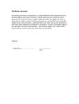
1
EverExceed PowerLead2
RM Series UPS(1-3K)
user manual
www.everexceed.com
Important Safety Instructions
Important Safety Instructions
This manual contains important safety instructions. Read all safety and operating instructions
before operating the uninterruptible power systems (UPS). Adhere to all warnings on the unit
and in this manual. Follow all operating and user instructions. This equipment can be operated
by individuals without previous training.
Maximum load must not exceed that shown on the UPS rating label. The UPS is designed for
data processing equipment. If uncertain, consult your dealer or local representative.
The PL2 RM Series 1-3kVA@200/208/220/230/240VAC is designed for use with a three-wire
input (L,N,G).
WARNING
The battery can present a risk of electrical shock and high
short circuit current. Following precautions should be
observed before replacing the battery.
l
Wear rubber gloves and boots.
l
Remove rings, watches and other metal objects.
l
Use tools with insulated handles.
l
Do not lay tools or other metal objects on the batteries.
l
If the battery is damaged in any way or shows signs of leakage, contact your local
representative immediately.
l
Do not dispose of batteries in a fire. The batteries may explode.
l
Handle, transport and recycle batteries in accordance with local representative.
WARNING
Although the UPS has been designed and manufactured to
ensure personal safety, improper use can result in electrical
shock or fire. To ensure safety, observe the following
precautions:
l
Turn off and unplug the UPS before cleaning it.
l
Clean the UPS with a dry cloth. Do not use liquid or aerosol cleaners.
l
Never block or insert any objects into the ventilation holes or other openings of the UPS.
l
Do not place the UPS power cord where it might be damaged.
PowerLead 2 RM Series 1-3k UPS User Manual
I
Contents
CONTENTS
Important Safety Instructions ....................................................................................................I
1.Electromagnetic Compatibility...............................................................................................1
2. Introduction .........................................................................................................................2
3.1 Transient Voltage Surge Suppression (TVSS) and EMI/FRI Filters ............................... 5
3.2 Rectifier/Power Factor Correction (PFC) Circuit ........................................................... 5
3.3 Inverter......................................................................................................................... 5
3.4 Battery Charger............................................................................................................ 5
3.5 DC-to-DC Converter..................................................................................................... 6
3.6 Battery ......................................................................................................................... 6
3.7 Dynamic Bypass .......................................................................................................... 6
4. Product Specification and performance ...............................................................................7
4.1 Model Description ........................................................................................................ 7
4.2 Product Specification and Performance........................................................................ 7
5. Installation ...........................................................................................................................9
5.1 Unpacking and Inspection ............................................................................................ 9
5.2 Mechanical Installation ................................................................................................. 9
5.2.1 Notes for installation.............................................................................................9
5.2.2 Tower Installation .................................................................................................9
5.2.3 Rack Installation................................................................................................. 12
5.3 Operating procedure for connecting the long backup time model UPS with the external
battery.............................................................................................................................. 13
6. Controls and Indicators...................................................................................................... 15
6.1 Operation and Display Panel...................................................................................... 15
6.2 Audible Alarm ............................................................................................................. 18
7. Operation .......................................................................................................................... 19
7.1 Operation Mode ......................................................................................................... 19
II
PowerLead 2 RM Series 1-3k UPS User Manual
Contents
8. Battery Maintenance.......................................................................................................... 20
8.1 Battery maintenance .................................................................................................. 20
8.2 Replacing Internal Battery Pack ................................................................................. 20
9. Notes for battery disposal and replacement procedures .................................................... 24
9.1 Battery Disposal ......................................................................................................... 24
9.2 Battery Replacement Procedures............................................................................... 24
10. Trouble shooting .............................................................................................................. 25
10.1 Checking UPS status................................................................................................ 25
10.2 Adjust the factors caused the problem ...................................................................... 25
Annex A. Intelligent Slot......................................................................................................... 29
Annex B. EPO ....................................................................................................................... 30
Annex C. Rated Parameters Setting ...................................................................................... 31
Annex D. Battery Kit Assembly (option) ................................................................................. 33
PowerLead 2 RM Series 1-3k UPS User Manual
III
Electromagnetic Compatibility
1.Electromagnetic Compatibility
* Safety
IEC/EN 62040-1-1
* EMI
Conducted Emission.........IEC/EN 62040-2
Class A
Radiated Emission............IEC/EN 62040-2
Class A
*EMS
ESD..................................IEC/EN 61000-4-2
Level 4
RS....................................IEC/EN 61000-4-3
Level 3
EFT..................................IEC/EN 61000-4-4
Level 4
SURGE............................IEC/EN 61000-4-5
Level 4
Low Frequency Signals..............:IEC/EN 61000-2-2
Warning: This is a product for commercial and industrial application in the second
environment-installation restrictions or additional measures may be needed to
prevent disturbances.
NOTICE:
This is a product for restricted sales distribution to informed partners. Installation restrictions or
additional measures may be needed to prevent radio interference.
Operated the UPS in an indoor enviroment only in an ambient temperature range of
0-40°C(32-104°F). Install it in a clean environment, free from moisture, flammable liquids,
gases and corrosive substance.
This UPS contains no user-serviceable parts except the internal battery pack. The UPS on/off
push buttons do not electrically isolate internal parts. Under no circumstance attempt to gain
access internally, due to the risk of electric shock or burn.
Do not continue to use the UPS if the panel indications are not in accordance with these
operating instructions or the UPS performance alters in use. Refer all fault to your dealer.
Servicing of batteries should be performed or supervised by personnel knowledgeable of
batteries and the precautions. Keep unauthorized personnel away from the batteries. Proper
disposal of batteries is required. Refer to your local laws and regulations for disposal
requirement.
DO NOT CONNECT equipment that could overload the UPS or demand DC current from the
UPS, for example: electric drills, vacuum cleaners, laser printers, hair dryer or any appliance
using half-wave rectification.
Storing magnetic media on top of the UPS may result in data loss or corruption.
Turn off and isolate the UPS before cleaning it. Use only a soft cloth, never liquid or aerosol
cleaners.
PowerLead 2 RM Series 1-3k UPS User Manual
1
System Description
2. Introduction
Congratulations on your choice of the PowerLead 2(PL2) RM Series UPS, the UPS comes in
nominal power ratings of 1000VA,2000VA and 3000VA. It is designed to provide conditioned
power to microcomputers and other sensitive electronic equipment.
When it is generated, alternating current is clean and stable. However, during transmission and
distribution it may be subject to voltage sags, spikes and complete power failure that may
interrupt computer operations, cause data loss and even damage equipment. The UPS
protects equipment from these disturbances.
The UPS is a compact, on-line UPS. An on-line UPS continuously conditions and regulates its
output voltage, whether utility power is present or not. It supplies connected equipment with
clean sinewave power. Sensitive electronic equipment operates best from sinewave power.
For ease of use, the UPS features a LCD display to indicate all information for UPS, and
provide kinds of function buttons.
Fig.1 Front View
2
PowerLead 2 RM Series 1-3k UPS User Manual
System Description
Fig.2 Rear View
PowerLead 2 RM Series 1-3k UPS User Manual
3
System Description
RS-232 communication port. DB9 type.
EPO. Short to activate.
Intelligent slot
USB port. B type.
Input surge protection slot.
Input socket. 1KVA: IEC C14, 2K/3K: IEC C20
Network surge protection.
Output Socket IEC C13
External battery port. Optional for standard model.
Battery ground
Output Socket IEC C19
In addition, in view of the long backup time requirements, Specially designed the battery pack,
the diagram below:
Fig.3-1Front View of Battery pack
Fig.3-2 Rear View of Battery pack
4
PowerLead 2 RM Series 1-3k UPS User Manual
System Description
3. System Description
3.1 Transient Voltage Surge Suppression (TVSS) and EMI/FRI Filters
These UPS components provide surge protection and filter both electromagnetic interference
(EMI) and radio frequency interference (RFI). They minimize any surge or interference present
in the utility line and keep the sensitive equipment protected.
3.2 Rectifier/Power Factor Correction (PFC) Circuit
In normal operation, the rectifier/power factor correction (PFC) circuit converts utility AC power
to regulated DC power for use by the inverter while ensuring that the waveform of the input
current used by the UPS is near ideal. Extracting this sinewave input current achieves two
objects:
l
The utility power is used as efficiency as possible by the UPS.
l
The amount of distortion reflected on the utility is reduced.
This results in cleaner power being available to other devices in the building not being
protected by the UPS.
3.3 Inverter
In normal operation, the inverter utilize the DC output of the power factor correction circuit and
inverters it into precise, regulated sinewave AC power. Upon a utility power failure, the inverter
receives its required energy from the battery through the DC-to-DC converter. In both modes of
operation, the UPS inverter is on-line and continuously generating clean, precise, regulated AC
output power.
3.4 Battery Charger
The battery charger utilizes energy from the utility power and precisely regulates it to
continuously float charge the batteries. The batteries are being charged whenever the UPS is
connected to utility power.
PowerLead 2 RM Series 1-3k UPS User Manual
5
System Description
3.5 DC-to-DC Converter
The DC-to-DC converter utilizes energy from the battery system and raises the DC voltage to
the optimum operating voltage for the inverter. The converter includes boost circuit which is
also used as PFC.
3.6 Battery
The standard model include value-regulated, non-spillable, lead acid batteries inside. To
maintain battery design life, operate the UPS in an ambient temperature of 14-25°C.
3.7 Dynamic Bypass
The UPS provides an alternate path for utility power to the connected load in the unlikely event
of a UPS malfunction. Should the UPS have an overload, over temperature or any other failure
condition, the UPS automatically transfers the connected load to bypass. Bypass operation is
indicated by an audible alarm and illuminated amber Bypass LED.
NOTICE:The bypass power path does NOT protect the connected equipment from
disturbances in the utility supply.
6
PowerLead 2 RM Series 1-3k UPS User Manual
Production Specification and Performance
4. Product Specification and performance
4.1 Model Description
This manual is applicable to the following models:
Model No.
Type
PL2 RM1K/2K/3K
Standard model
PL2 RM1KL/2KL/3KL
Long backup model
“L” Model: Long backup time.
4.2 Product Specification and Performance
1. General Specification
Model
PL2
PL2
PL2
PL2
PL2
PL2
RM1KL
RM1K
RM2KL
RM2K
RM3KL
RM3K
Power Rating
1KVA/0.9KW
2KVA/1.8KW
3KVA/2.7KW
Frequency (Hz)
50/60
50/60
50/60
Input
Battery
Voltage
110Vac~288Vac
Current
5.5A max.
11A max
16A max
Voltage
36VDC
72VDC
96VDC
Current
35A max
35A max
37A max
Voltage
Output
Current
200V/208V/220V/230V/240V
5/4.8/4.5/4.3/4.2A
Dimension
(WxDxH) mm
Weight (kg)
10/9.6/9/8.6/8.4A
6A
438*477* 438*477* 438*477* 438*477*
438*426*86
8
15/14.4/13.5/12.9/12.
13.5
86
173
86
173
9.5
28
10.5
33
2. Electrical Performance
Input
Model
Voltage
Frequency
Power Factor
1-3KVA
Single-phase
40-70Hz
>0.98(Full load)
PowerLead 2 RM Series 1-3k UPS User Manual
7
Product Specification and performance
Output
Voltage
Power Frequency
Regulation Factor
Distortion
tolerance.
Overload capacity
THD<1%@Fu
±1%
0.9 lag
±0.5% of
normal
ll Linear Load
THD<6%@Fu
ll nonlinear
load
Crest ratio
130% load: transfers to
Bypass mode after 1
3:1
minutes
150% load: transfers to
maximum
Bypass mode after 0.5
minute
3. Operating Environment
Temperature
Humidity
Altitude
Storage temperature
0°C-40°C
<95%
<1000m
-20°C-70°C
NOTICE:If the UPS is installed or used in a place where the altitude is above than 1000m,
the output power must be derated in use, please refer to the following:
Altitude (M)
8
1000
1500
2000
2500
3000
3500
4000
4500
5000
Derating Power 100%
95%
91%
86%
82%
78%
74%
70%
67%
PowerLead 2 RM Series 1-3k UPS User Manual
Installation
5. Installation
NOTICE:UPS operation in sustained temperature outside the range of 14-25°C (59°-77°F)
reduces battery life.
5.1 Unpacking and Inspection
1) Unpack the packaging and check the package contents. The shipping package contains:
● 1 UPS
● 1 user manual
● 1 Input Cable
● 1 RS232 Cable
● 2 Bracket Ear
● 1 Battery Cable (For Long backup model only)
2) Inspect the appearance of the UPS to see if there is any damage during transportation.
Do not turn on the unit and notify the carrier and dealer immediately if there is any
damage or lacking of some parts.
5.2 Mechanical Installation
Two installation modes are available: tower installation and rack installation, depending
on available space and use considerations. You can select an appropriate installation
mode according to the actual conditions.
5.2.1 Notes for installation
1)
The UPS must be installed in a location with good ventilation, far away from water,
inflammable gas and corrosive agents.
2)
Ensure the air vents on the front and rear of the UPS are not blocked so as to
ensure good ventilation.
3)
Condensation to water drops may occur if the UPS is unpacked in a very low
temperature environment. In this case it is necessary to wait until the UPS is fully
dried inside out before proceeding installation and use. Otherwise there are hazards
of electric shock.
5.2.2 Tower Installation
Various installation configurations are available: single UPS, single UPS with single or
multiple battery cabinets. Their installation methods are all the same.
PowerLead 2 RM Series 1-3k UPS User Manual
9
Installation
The installation procedures are as follows:
Step 1: Take out the support bases from the accessories. Their appearances are shown in
Fig.4-1.
Fig.4-1 Support bases
Step 2: If optional external battery cabinets are connected to the UPS to provide
additional battery run time, assemble the spacers and the support bases, as shown in
Fig.4-2.
Fig.4-2 Installing support bases with spacers
Step 3: Adjust the direction of UPS operation and display panel and LOGO.
1. Remove the front plastic bezel cover gently, as shown in Fig.4-3.
Fig.4-3 Removing the front plastic bezel cover
10
PowerLead 2 RM Series 1-3k UPS User Manual
Installation
2. Pull the operation and display panel gently, rotate it 90 degrees clockwise and snap it
back into position, as shown in Fig.4-4
Fig.4-4 Rotating the operation and display panel
3. Pull the LOGO on the front plastic bezel cover gently, rotate it 90 degrees clockwise
and snap it back into position. After rotation, the front plastic bezel cover is shown in
Fig.4-5.
Fig.4-5 Rotate it 90 degrees clockwise and snap it back into position
4. Restore the front plastic bezel cover to the UPS. At this point, the UPS operation and
display panel and LOGO have been rotated 90 degrees clockwise, which provides
upright viewing for users.
PowerLead 2 RM Series 1-3k UPS User Manual
11
Installation
Step 4: Place the UPS (and battery cabinet) on the support bases. Each UPS needs two
pairs of support bases to install, as shown in Fig.4-6.
Fig.4-6 Tower installation
5.2.3 Rack Installation
1.
Various installation configurations are available: single UPS, single UPS with single
or multiple-battery. Their installation methods are all the same.
2.
Because battery cabinets are too heavy, they must be installed first, and two or more
installation personnel are required to install them at the same time. Please install them
from bottom to top.
Rack installation: fix the UPS and battery cabinet onto the rack through brackets.
Installation method:
1.
Take out two brackets and six M4 × 10 screws from the accessories, and fix the
brackets onto the UPS using the screws through installation hole, as shown in Fig.4-7.
12
PowerLead 2 RM Series 1-3k UPS User Manual
Installation
Fig.4-7 Installing brackets
2.
Place the UPS onto the guide rail in the rack, and push it completely into the rack
along the guide rail (it is prohibited to move the UPS through the brackets). And fix
the UPSt onto the rack using the screws through installation hole on the bracket, as
shown in Fig.4-8.
Fig.4-8 Installing UPS
5.3 Operating procedure for connecting the long backup time model UPS with the
external battery
Notice: Please connect the external battery at least 40AH while the charge current is 8A,
at least 20AH for 4A.otherwise may cause damage to the battery.
PowerLead 2 RM Series 1-3k UPS User Manual
13
Installation
1.
The nominal DC voltage of external battery pack is 36VDC/1kVA, 72VDC/2kVA,
96VDC/3kVA. Connect in series the batteries of the pack to ensure proper battery
voltage. To achieve longer backup time, it is possible to connect multi-battery packs,
but the principle of “same voltage, same type” should be strictly followed.
Fig.4-9 Battery terminal connection
2.
Take out battery cable delivered with the UPS. One end of battery cable is a plug and
the other end has 2 open wires.
3.
Connect the RED wire to the “+” terminal of the battery. Connect the BLACK wire to
the “-“ terminal of the battery.
Notice: DO NOT connect the battery plug to the battery socket of UPS first, otherwise, it
may cause electric shock.
4.
14
Connect the external battery plug to the battery socket on the rear panel.
PowerLead 2 RM Series 1-3k UPS User Manual
Controls and Indicators
6. Controls and Indicators
6.1 Operation and Display Panel
Fig.5 Display Panel
Description of Panel
Controls
Description
1.Press ON/OFF to start UPS when utility is normal
NOTE
It only bases on default setting(manual start)
2.Press ON/OFF to start from battery directly when there is no
main input, press again to start UPS upon buzzer alarms
ON/OFF
3.Press ON/OFF to shutdown inverter when UPS is in normal
mode.
4.Press ON/OFF to shutdown UPS completely when UPS is in
battery mode
5.Press ON/OFF to ensure the rated parameter setting
1.Press FUNC button to transfer in different menus
2.Press FUNC button for 2.5 seconds to mute off
FUNC
3.Press FUNC and ON/OFF together for 2.5 seconds to set rated
parameters when only power supply is on
Indicators
Description
PowerLead 2 RM Series 1-3k UPS User Manual
15
Controls and Indicators
Rectifier indicator:
green--rectifier is normal,
REC
green flicker--rectifier is starting,
dark—rectifier is not working
Inv indicator:
green--inverter is normal
Inv
green flicker--inverter is starting or tracking with bypass(ECO)
dark—inverter is not working
Bypass indicator:
yellow—bypass is normal
BYP
yellow flicker—yellow flicker—The utility power input is ok, But not
start the ups.
dark—bypass is not working
Battery indicator:
yellow—battery discharge or charged
BAT
yellow flicker—battery is not connected, battery is low or charger is
failure
dark—battery is connected
Fig 6. LCD Main Menu
16
PowerLead 2 RM Series 1-3k UPS User Manual
Controls and Indicators
Description of Main Menu
Display
Function
Input information
Submenu
Input voltage(VAC),
Input frequency(Hz),
Input current(A)
Fault code(FAULT),
Warn code(WARN),
working mode(First number: n-normal mode,
E-ECO mode. Second number: rated voltage and
frequency
Warn information
0-200V/50Hz,
1-200V/60Hz,
2-208V/50Hz,
3-208V/60Hz,
4-220V/50Hz,
4-220V/60Hz,
6-230V/50Hz,
7-230V/60Hz,
8-240V/50Hz, 9-240V/60Hz) mute on(
off(
Battery information
), mute
)
Battery voltage(VDC), Capacity(%) if needed,
Firmware version,
Battery low warn(LOW)
Load information
Load percent(%)
Active load(kW)
Apparent load(kVA)
Protocol code in setting mode
Output information
Output voltage(VAC)
Output frequency(Hz)
Output current(A)
Note: Press “FUNC” button to see different information.
PowerLead 2 RM Series 1-3k UPS User Manual
17
Controls and Indicators
6.2 Audible Alarm
Condition
No.
Alarm
1
Battery discharge
Sounding every 2 minutes
2
Low battery
Sounding every 6 seconds
3
Overload
Continuous beeping
4
Input voltage abnormal
Sounding every 2 minutes
18
PowerLead 2 RM Series 1-3k UPS User Manual
Operation
7. Operation
7.1 Operation Mode
1. Turn on the UPS in normal mode
1) After you make sure that the power supply connection is correct, and then close the
battery breaker (this step only for long backup time model), after that turn on the
utility power. At this time the fans rotate, and LCD is on
2) Press ON/OFF for about 1 second, REC led will green flicker. Inverter will start and
the INV green led flickers when REC led is green
NOTE
In some application, UPS is set to start automatically, there will be something
different.
3)
About several seconds, the UPS turn into normal Line mode. If the utility power is
abnormal, the UPS will operate in Battery mode without output interruption of the
UPS.
2. Turn on the UPS from battery without utility power
1) After you make sure that the breaker of the battery pack is in the “ON” position (this
step only for long backup time model), press the ON/OFF button once to power on
the LCD, then press ON/OFF button again for 1 second when the buzzer alarms
2) A few seconds later, the UPS turns into Battery mode, and inverter feed the load.
3. Turn off the UPS in normal mode
1) Press ON/OFF button in condition of normal mode
2) Turn off utility power
3) If it’s a long backup model, open the battery breaker to turn off UPS completely. If it’s
an internal battery model, the UPS will shutdown completely after several seconds.
4. Turn off the UPS in battery mode
1) To power off the UPS by pressing the ON/OFF button continuously for more than 1
second
2) When being powered off, the UPS will turn into No Output mode. Finally not any
display is shown on the display panel and no voltage is available from the UPS
output.
NOTICE:Please turn off the connected loads before turning on the UPS and turn on the loads
one by one after the UPS is working in INV mode. Turn off all of the connected loads before
turning off the UPS.
PowerLead 2 RM Series 1-3k UPS User Manual
19
Battery Maintenance
8. Battery Maintenance
8.1 Battery maintenance
1-3KVA UPS only requires minimal maintenance. The batteries used for standard models are
value regulated, sealed lead-acid, maintenance free battery. When being connected to the
utility power, whether the UPS is turned on or not, the UPS keeps charging the batteries and
also offers the protective function of overcharging and over-discharging.
lThe UPS should be charged once every 4 to 6 months if it has not been used for a long
time.
lIn the regions of hot climates, the battery should be charged and discharged every 2
months. The standard charging time should be at least 12 hours.
lUnder normal conditions, the battery life lasts 3 to 5 years. In case if the battery is found
in bad condition, earlier replacement should be made.
lBattery replacement should be performed by qualified personnel.
lReplace batteries with the same number and same type of batteries.
lDo not replace the battery individually. All the batteries should be replaced at the same
time following the instructions of the battery supplier.
8.2 Replacing Internal Battery Pack
Battery replacement procedures
Step 1: Gently remove the front plastic bezel cover from the UPS.
Step 2: Loosen and remove the screws on the battery door, as shown in Fig.7-1. Lay
the battery door aside for reassembly.
20
PowerLead 2 RM Series 1-3k UPS User Manual
Battery Maintenance
Fig.7-1 Removing the front plastic bezel cover and battery door
PowerLead 2 RM Series 1-3k UPS User Manual
21
Battery Maintenance
Step 3: Gently pull the battery wire out and disconnect battery wires, as shown in
Fig.7-2.
Fig.8-2 Disconnect battery wires
Step 4: Grasp the battery handle, and pull the internal battery pack out of the UPS, as
shown in Fig.7-3.
22
PowerLead 2 RM Series 1-3k UPS User Manual
Battery Maintenance
Fig.7-3 Pulling out the internal battery pack
Step 5: Unpack the new internal battery pack. Take care not to destroy the packing.
Compare the new and old internal battery pack to make sure they are the same. If so,
proceed with Step 6; otherwise stop operation and contact your local dealer.
Step 6: Line up and slide in the new internal battery pack.
Step 7: Reconnect the battery plug and battery receptacle, and gently push the
battery wire and internal battery pack back into the UPS.
Step 8: Reattach the front battery door with the three screws.
Step 9: Reattach the front plastic bezel cover to the UPS.
(For battery kit assembly, refer to Annex D)
NOTICE:Do not replace the internal battery pack while the UPS is operating in Battery Mode.
This will result in a loss of output power and will drop the connected load. Moreover, it will
jeopardize personnel safety!
PowerLead 2 RM Series 1-3k UPS User Manual
23
Notes for battery disposal and replacement procedures
9. Notes for battery disposal and replacement procedures
9.1 Battery Disposal
1)
Before disposing of batteries, remove jewelry, watches and other metal objects.
2)
Use rubber gloves and boots, use tools with insulated handles.
3)
If it is necessary to replace any connection cables, please purchase the original
materials from the authorized distributors or service centers, so as to avoid overheat
or spark resulting in fire due to insufficient capacity.
4)
Do not dispose of batteries or battery packs in a fire. The batteries may explode.
5)
Do not open or mutilate batteries, released electrolyte is highly poisonous and
harmful to the skin and eyes.
6)
Do not short the positive and negative of the battery electrode, otherwise, it may
result in electric shock or fire.
7)
Make sure that there is no voltage before touching the batteries. The battery circuit is
not isolated from the input potential circuit. There may be hazardous voltage
between the battery terminals and the ground.
8)
Even though the input breaker is disconnected, the components inside the UPS are
still connected with the batteries, and there are potential hazardous voltages.
Therefore, before any maintenance and repairs work is carried out, switch off the
breaker of the battery pack or disconnect the jumper wire of connecting between the
batteries.
9)
Batteries contain hazardous voltage and current. Battery maintenance such as the
battery replacement must be carried out by qualified personnel who are
knowledgeable about batteries. No other persons should handle the batteries
9.2 Battery Replacement Procedures
1)
Turn off UPS completely.
2)
Remove covers from the UPS.
3)
Disconnect the battery wires one by one.
4)
Remove metal bars which are used to fasten batteries.
5)
Replace batteries one by one.
6)
Screw metal bars back to UPS.
7)
Connect the battery wires one by one. Take care of electrical shock while
connecting the last wire.
24
PowerLead 2 RM Series 1-3k UPS User Manual
Trouble Shooting
10. Trouble shooting
This section describes checking the UPS’ status. This section also indicates various UPS
symptoms a user may encounter and provides a troubleshooting guide in the event the UPS
develops a problem. Use the following information to determine whether external factors
caused the problem and how to remedy the situation.
10.1 Checking UPS status
It recommended that checking the UPS operation status every six months.
l
Check whether the UPS is faulty: Is the Fault Indicator on? Is the UPS sounding an
alarm?
l
Check whether the UPS is operating in Bypass mode. Normally, the UPS operates
in Normal Mode. If it is operating in Bypass Mode, stop and contact your local
representative, or Channel Support.
l
Check whether the battery is discharging. When the utility input is normal, the
battery should not discharge. If the UPS is operating in Battery Mode, stop and
contact your local representative, or Channel Support.
10.2 Adjust the factors caused the problem
When the fault indicator is on, press FUNC button to see the fault code and warn code. Fault
and warn codes are listed as following:
Code
Event
Possible cause
Solution
7
Warn: Battery not
Battery not connected
Check if battery switch is off or
connected
10
battery cables are disconnected
Warn: EPO
Emergency power off
Short the EPO terminal 1&2 to
activate EPO
12
Warn:
Inverter
capacity
/
/
Utility is failure
/
not
enough
16
Warn:
Input
voltage abnormal
18
Input surge protector
If utility is normal but rectifier is not
opens
working, reset input surge protector
Warn: Line neutral
Input Line and neutral
Check the polarity of line wire and
wires reversed/PE
is reversed
neutral wire
not grounded
PE
not
Check if PE on input plug is shorted
connected correctly in
wire
is
with UPS rear panel. If not ,contact
UPS
with distributer or service center. If
PowerLead 2 RM Series 1-3k UPS User Manual
25
Trouble Shooting
yes, please check PE wire in input
power socket
20
Warn:
Bypass
voltage abnormal
Bypass voltage is out
Check if utility power is indeed out of
of bypass range or is
range.
off
24
Warn: Bypass over
Load is on bypass and
Remove some loads to ensure that
load
is overload
total loads is less than 95% of rated
capacity
26
Warn:
Bypass
overload timeout
Load is on bypass and
Remove some loads and restart
overload.
UPS again. When UPS is working
Overload
time is longer than the
normally, turn on loads one by one.
overload capacity of
bypass.
UPS
will
shutdown output and
loads will loss power.
28
Warn:
Bypass
Bypass frequency is
frequency is out of
out
synchronous
range.
of
/
synchronous
range
30
32
Warn:
Transfer
times
Check if output is overload or some
times over limit in
between inverter and
loads are shorted. Remove the
1 hour
bypass is over 5 in
failure loads and restart the UPS or
recent 1 hour. UPS
wait
works in bypass mode.
automatically.
Something shorted
Please remove all loads from UPS
Warn:
output
Transfer
shorted
for
starting
inverter
output. Check if UPS output is
shorted. If not, please check all
loads.
34
Warn:
End
of
discharge
UPS works in battery
Please save your data when UPS
mode for long time
alarm “utility fail”
after utility failure. UPS
output will be off until
utility power is on.
47
Fault:
fault
26
Rectifier
Bus over voltage, bus
Please contact with distributer or
unbalance,
service center.
rectifier
PowerLead 2 RM Series 1-3k UPS User Manual
Trouble Shooting
starting
failure,
bus
under voltage, input
fuse is off
49
51
Fault: Inverter fault
Inverter over voltage,
Please contact with distributer or
inverter under voltage,
service center.
Warn: UPS over
Environment
Please ensure that nothing blocks
temperature
temperature is higher
ventilation and environmental temp
than permitted point,
must be 0~40°C
ventilation is blocked
53
Fault: Fan failure
One or more fans are
Please contact with distributer or
failure, fan wires are
service center
loosen
55
Warn:
Inverter
overload
57
Warn:
Inverter
overload timeout
Loads are on inverter
Remove some loads to ensure that
and over the capacity
total loads is under the capacity of
of the UPS
the UPS
Load
is
over
the
Remove some loads to under 95%,
capacity of the UPS
UPS
and timeout, UPS will
automatically
transfer
mode
to
if
will
transfer
to
inverter
bypass
bypass
is
available
65
Warn: Battery low
UPS works in battery
Recover input power or save data
and battery voltage is
upon “battery low”
low
71
72
74
Fault:
There is no charger
Please contact with distributer or
fault
Charger
output.
service center
Warn: input over
Abnormal large current
Please contact with distributer or
current
enter in rectifier.
service center
UPS
/
Warn:
Manual
shutdown
will
shutdown
output or transfer to
bypass mode
/
Battery discharge
The battery has not
Charge the battery for more than 10
time diminishes
been fully charged
hours
UPS is overload
Check the loads and remove some
devices
PowerLead 2 RM Series 1-3k UPS User Manual
27
Trouble Shooting
Battery aged
Replace
the
batteries.
Please
contact with distributer or service
center
to
obtain
replacement
components for batteries.
NOTICE
Please provide the following information when reporting fault UPS:
1)
The UPS model and serial NO.
2)
The warn and fault code happened
3)
Detail of fault, include LED indicates, buzzer beeps, power condition, load capacity
and configuration of battery(long backup time model)
28
PowerLead 2 RM Series 1-3k UPS User Manual
EPO
Annex A. Intelligent Slot
There are two types of intelligent slot for option: DB9, phoenix terminator.
Max output current for intelligent slot is 1A.
The functions of intelligent slot are listed as fig.8-1 and fig.8-2:
Fig.8-1 DB9 type
Fig.8-2 phoenix terminator type
Description of intelligent slot:
Function
Description
UPS fail
Low voltage if something is failure in UPS. If not, high voltage
General alarm
Low voltage if something is abnormal. If not, high voltage
GND
Common connection
This is the only input signal, use it you can remote turn on or turn off the UPS.
When the UPS working in LINE-Mode, The signal change from high level to low
level, UPS will shutdown rectifier and inverter. The signal change from low level
to high level, UPS will turn on rectifier and inverter one by one.
When the UPS working in BAT-Mode, The signal change from high level to low
level, UPS will shutdown inverter and output .
Close switch mean high level.
Remote
shutdown
Power supply
12VDC~24VDC, external power supply
Bypass mode
High voltage if UPS works in bypass mode. If not, low voltage
Battery low
Low voltage if battery voltage is low. If not, high voltage
Normal mode
High voltage if UPS works in normal mode. If not, low voltage
Utility fail
Low voltage if utility is failure. If not, high voltage.
PowerLead 2 RM Series 1-3k UPS User Manual
29
EPO
Annex B. EPO
EPO(Emergency Power Off) is optional function to shutdown UPS completely at emergency
condition. This function can be activated through a remote contact or a similar switch provided
by the user. Normal, EPO terminals without short, When emergencies happen to short the EPO
terminals, EPO effect function, UPS close the rectifier ,inverter output immediately,
schematic diagram is as follows:
Fig.9 EPO effect function
30
PowerLead 2 RM Series 1-3k UPS User Manual
Rated Parameters Setting
Annex C. Rated Parameters Setting
Rated parameters of 1-3K UPS can be set from panel. Please set rated parameters in
according to the following procedures:
1)
Start UPS power supply and ensure that rectifier, inverter, bypass and discharge are not
working.
2)
Press ON/OFF and FUNC together for 2.5 seconds to enter in setting mode, all LEDs
flicker.
3)
Voltage setting: press FUNC to change rated voltage. Shown as following:
Current Rated
Voltage
VAC
INPUT
BYPASS
CONVERTER
VAC
OUTPUT
LOAD
4)
Frequency setting: Press ON/OFF to choose voltage and enter in frequency setting. Press
FUNC to change rated frequency. Shown as following:
5)
Mode setting: press ON/OFF to choose frequency and enter in mode setting, press FUNC
to change mode. First code: n-normal mode, E-ECO mode. Second code indicated
current voltage/frequency are listed in description of main menu in section 6.
PowerLead 2 RM Series 1-3k UPS User Manual
31
Rated Parameters Setting
6)
Protocol setting: press ON/OFF to choose mode and enter in protocol setting. Codes are
shown in LOAD, press FUNC to change protocol. First code: 0-Modbus, 1-SNT,
“CC”-current protocol.
7)
Press ON/OFF to choose protocol and display current setting.
Current voltage
VAC
INPUT
Current frequency
BYPASS
Hz
CONVERTER
MODE
Current mode
8)
OUTPUT
LOAD
Current protocol
Press ON/OFF to save current setting and exit. If want to change, press FUNC and repeat
the procedures above.
9)
If you want to exit from setting mode and give up saving, press ON/OFF and FUNC
together for 2.5 seconds when in setting mode.
10)
32
Restart and check if the setting is right.
PowerLead 2 RM Series 1-3k UPS User Manual
Battery Kit Assembly (option)
Annex D. Battery Kit Assembly (option)
1k battery kit
PowerLead 2 RM Series 1-3k UPS User Manual
33
Battery Kit Assembly (option)
2k battery kit
34
PowerLead 2 RM Series 1-3k UPS User Manual
Battery Kit Assembly (option)
3k battery kit
PowerLead 2 RM Series 1-3k UPS User Manual
35
66001- 00298
V1.0版