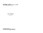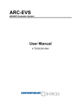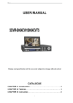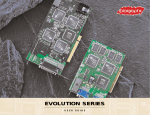
1
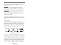
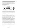
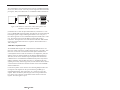
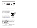
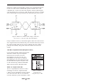
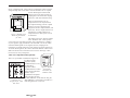
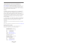
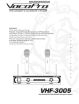
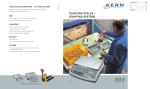
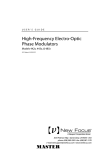
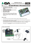
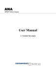
PCM20H
ARCNET® Network Interface Modules for PC Card Computers
INSTALLATION GUIDE
INTRODUCTION
The PCM20H series of ARCNET network interface modules (NIMs) links
PC Card compatible computers with the ARCNET local area network
thereby providing ARCNET connectivity to laptop and notebook style
computers.
The PCM20H conforms to release 2.1 of the PC Card standard Type II (5.0
mm thick) cards. The ARCNET transceiver circuitry is located in a
detachable MAU (medium access unit) which plugs into the PCM20H
adapter. MAUs exist for various cabling media such as coaxial cable and
twisted-pair cable and are all interchangeable with one another. A 15-pin
connector with a short cable attaches the MAU to the adapter.
The PCM20H incorporates the COM20022 ARCNET controller with
enhanced features over earlier generation ARCNET chips. New features
include command chaining, sequential access to internal RAM, duplicate
node ID detection and variable data rates. Data rates from 156 kbps to
10 Mbps are possible.
There are several versions of the PCM20H, each of which is designated by a
particular transceiver. The PCM20H-CXB can support either coaxial star or
bus networks. The PCM20H-TB5 and PCM20H-TPB support twisted-pair
bus with either RJ-45 or RJ-11 connectors. The PCM20H-485D supports
non-backplane mode DC EIA-485. The PCM20H-485X supports nonbackplane mode AC EIA-485. The PCM20H-485 supports backplane mode
DC EIA-485 while the PCM20H-485T supports backplane mode AC
EIA-485.
The PCM20H is shipped with a 3.5" (9cm) disk containing our DOS,
Windows 3.x, and Windows 95, 98 enabler software. Once loaded,
programs written for the PCX20 will transparently operate with the
PCM20H.
The PCM20H is primarily intended for industrial applications. Although
functionally equivalent to its predecessors the PCM20 and PCM20E, the
PCM20H has improved EMC performance, ruggedized MAU case and
locking MAU connector. The PCM20, PCM20E and PCM20H are all
software compatible.
SPECIFICATIONS
Environmental
Operating temperature:
Storage temperature:
Data Rates
PCM20H*
*
0°C to +55°C
-20°C to +65°C
10 Mbps, 5 Mbps, 2.5 Mbps, 1.25 Mbps, 625 kbps,
312.5 kbps, 156.25 kbps
The -CXB, -TB5, and TPB models can only operate at 2.5 Mbps.
The -485X and -485T models can only operate at 1.25, 2.5, 5.0
or 10 Mbps.
Dimensions
Type II adapter:
MAU:
3.370"L x 2.126"W x 0.196"T
(85mm x 54mm x 5mm)
3.175"L x 1.835"W x 1.005"T
(81mm x 46mm x 26mm)
Cable
11.125" (28.3cm) Approx. MAU base to adpater base
Shipping Weight
1 lb. (.45kg)
I/O Mapping
Supports I/O mapping on any 16-byte boundary
Interrupt Lines
Supports IRQ2 through 15
Compatibility
PCM20H series NIMs are compliant with ANSI/ATA 878.1 and PC Card
Standard Feb. 1995.
Power Requirements
Model
PCM20H-CXB
PCM20H-TB5
PCM20H-TPB
PCM20H-485
PCM20H-485D
PCM20H-485X
PCM20H-485T
+5V
120mA
120mA
120mA
100mA
100mA
100mA
100mA
TD877123-0IA
2
INSTALLATION
The PCM20H conforms to release 2.1 of the PC Card standard Type II
(5.0 mm thick) cards. Consult your laptop or notebook user manual for
instructions on how to install the adapter card. Attached via a 15-conductor
cable to the adapter card is a medium access unit. Field connections are
made to the medium access unit.
DOS and Windows 3.1X Instructions
One of the design goals for the PCM20H PC Card ARCNET Adapter was to
use existing drivers without requiring software modifications to those
drivers. PCM20.EXE is a terminate-and-stay-resident (TSR) software utility
that configures the PC Card socket to match the requirements of the driver
software. PCM20.EXE must be executed before the driver attempts to
access the PCM20H PC Card ARCNET Adapter.
The command line for the PCM20.EXE utility is as follows:
pcm20 -p<port adr> -i<enable> -1<interrupt level> -n<node id> -e -h
where
-p<port address>
-i<enable>
sets the base address of the adapter
16 sequential addresses are used
enables the interrupt if <enable> is ‘1’
disables the interrupt if <enable> is ‘0’
-l<interrupt level> sets the IRQ number for the interrupts
-n<node id>
sets the node address in hexadecimal that is
stored on the PCM20H PC Card ARCNET
Adapter to simulate the DIP switch setting
-e
enables extended error reporting. This will cause the Card
Services vendor and version to be displayed. Additional
information about certain errors will also be displayed.
-h
displays the syntax of the PCM20.EXE command line
There are defaults built into the PCM20.EXE software. These defaults are
as follows:
port address:
interrupts:
IRQ level:
Node ID:
300h
disabled
IRQ5
0FFh
The Card Services software, which manages the PC Card
socket, will check the resources installed in your computer and will
complain if you attempt to request a resource that is already in use. For
example, if you have COM4 in your computer, the default base address is
TD877123-0IA
3
2E8h. If you request a base address of 2E0h for the PCM20H PC Card
ARCNET Adapter, Card Services will reject your request because of the
overlap occurring between 2E8h to 2EFh. If this occurs, you will either have
to select a different address for the PCM20H PC Card ARCNET Adapter, or
remove the COM4 hardware from your computer. Similar conflicts could
also occur with the requested interrupt levels.
If a conflict does occur, PCM20.EXE reports the problem and then exits
without remaining resident. If PCM20.EXE successfully configures the PC
Card socket, then it will remain resident. Once it is resident, executing it
again will report that it is already resident and will exit leaving the resident
version still in memory. The only way to remove the resident version is to
reboot the computer.
PCM20.EXE is intended for use with MS-DOS version 5.0 and above.
When resident, PCM20.EXE uses about 18K bytes of RAM in the lower
address space.
Base Port Address
When setting the port address, PCM20.EXE assumes that the right most
nibble of the base port address is 0. Therefore, use base addresses such as
300h, 310h and so on.
Node ID Switch Emulation
If the node ID switch logic is supported by the application software, enter
the desired node ID (non-zero value) in the command line. A zero will
prevent the adapter from joining the network. Remember that the node ID
switch is simply a register that may or may not be read by the application
software. It does not directly set the adapter node ID address. The
application software must do that.
Instructions for Windows 95/98/ME
Upon plugging the PCM20H into the PC Card slot you will be prompted for
a disk from the manufacturer. Use the provided disk and once installed your
PCM20H will appear to the system as a standard ISA COM20020
based ARCNET card. If you want to use this card for Windows NDIS based
networking, do NOT load this disk. Go to our web site at
http://www.ccontrols.com and retrieve the appropriate PCM20 NDIS driver.
Then create a new disk using the files from our site and provide this to
Windows when prompted for a “disk from the manufacturer.”
Under Windows 95, after you load the PCM20 enabler, you will be able to
adjust your PCM20H’s I/O base address. Under Windows 98, however, the
assigned I/O base address is not adjustable. If your driver or application
needs to have the PCM20H in the lower portion of I/O space (100-3FF), a
special Windows 98 enabler is available from our web site which will place
the PCM20H between 240 and 3F0 (hex).
TD877123-0IA
4
PCM20H Enabler for Windows 95/98/ME—Loading Instructions:
1.
Plug in your PCM20H PC Card.
2.
If the “New Hardware Found” dialog is shown, select the “Driver from
a disk provided by hardware manufacturer” option, insert this disk and
press “OK.” If the “Update Device Driver Wizard” dialog is shown,
then insert this disk and follow the instructions provided by Windows.
3.
Provide the system with the location of this floppy drive when
prompted (e.g. “a:\”). Some versions of Windows 95/ 98/ME may
report that the file pcm20.vxd cannot be found. If this occurs, enter the
location of this floppy disk in the box provided (e.g. “a:\”).
4.
The driver should now be loaded. Reboot the machine if requested by
Windows.
5.
Now proceed to the Windows Control Panel. Double click the System
icon. Choose the Device Manager tab. Select the “View devices by
type” option.
6.
The PCM20 should be listed as a generic category symbolized by a
gray diamond. It will not be listed under the network adapters
category. Double click this category and you should see a PCM20
device listed. Double click this device.
7.
Now choose the resources tab. Deselect the “Use automatic
settings” box. You can now modify your PCM20H’s resource settings
(I/O range and Interrupt Request). After modifying these parameters
press “OK.” You may then be prompted with a warning, press “Yes” to
continue.
8.
Your PCM20H should now be accessible at the I/O and Interrupt
settings you selected in step 7.
9.
You may also need to run the Setnode.exe program (located on this
disk) to set your node ID (see readme.txt). Some application programs
require the node ID to be set before they can operate correctly.
Software Utilities
The disk shipped with the PCM20H contains the files to enable the
PCM20H under DOS, Windows 3.x and Windows 95/98/ME. If you are
running DOS or Windows 3.x, please read the readme.dos file. If you are
running Windows 95/98/ME, please read the readme95.wri file.
This disk also contains several DOS utilities which can be used after your
PCM20H has been properly enabled.
IRQTEST.EXE:
This program will allow you to test your I/O and
interrupt settings. This program requires two parameters. The first
TD877123-0IA
5
parameter is the base I/O address of the PCM20H (in hex). The second
parameter is the interrupt setting used by the PCM20H (in decimal). For
example: irqtest 2E0 5.
NETMAP.EXE:
This program, which provides a list of the nodes
currently on your network, requires just the base I/O address of the
PCM20H (in hex). For example: netmap 2E0. This is an off-line utility
requiring at least two active nodes on the network in order to work.
SETNODE.EXE: This program provides the ability to set the node ID on
your PCM20H card. This program requires two parameters. The first
parameter is the base I/O address of the PCM20H (in hex). The second
parameter is the desired node ID (in hex). For example: setnode 2E0 1f.
FIELD CONNECTIONS
The PCM20H is available in several transceiver options. Each transceiver,
which is matched to a particular cable type, is identified by a three-digit
suffix appended to the model numbers. The capabilities of each transceiver
differs.
-CXB Coaxial Bus
For hubless systems, the -CXB transceiver can be used. NIMs are
interconnected with RG-62/u cables and BNC Tee connectors. Each -CXB
NIM represents a high impedance connection in both the powered and
unpowered states. Therefore, passive termination must be applied to both
ends of a bus segment. Use BNC style 93 (nominal) ohm resistors at each
end. The maximum segment length is 1000 feet and the maximum number
of NIMs that can be connected to a segment is eight.
Figure 1–Use BNC Tee connectors to
interconnect -CXB NIMs
To extend a bus segment beyond 1000 feet, an active hub is required. If the
hub port is of the -CXS type, connection can be made if a few simple rules
are followed. Only connect this type of hub port at the end of a bus segment.
Do not connect the hub to the middle of a segment since the hub port is not
of the high impedance type. Do not terminate the cable end which attaches
to the hub port since a -CXS port effectively terminates the end of a bus
segment. Simply remove the BNC Tee connector and terminator from the
segment end and attach the cable directly to the hub port. The opposite
segment end still requires termination if no hub connection is being made.
TD877123-0IA
6
Passive hubs should not be used with -CXB NIMs and only the use of
RG-62/u coaxial cable is recommended for segments. Contemporary
Controls (CC) also supplies BNC terminators and Tee connectors. Ask for
BNC-TER and BNC-T respectively. One note of caution, there is a
minimum cable length between nodes
(6 feet /2 meters). Do not violate this specification since unreliable
operation may result.
Figure 2–Bus segments can be extended through active hubs.
If star operation is required of the PCM20H instead of bus, simply connect a
BNC-TER and BNC-T to the end of the coaxial cable and then attach the
combination to the MAU. These accessories are included with the product.
This arrangement effectively converts the -CXB transceiver into a
-CXS compatible node.
-TB5, -TPB Twisted-Pair Bus
The -CXB transceiver can be modified to drive a balanced cable system
with the addition of some components. This configuration is called -TB5
and it supports shielded or unshielded twisted-pair cable such as IBM
type 3. Dual RJ-45 connectors replace the single BNC connector in order to
support the popular modular plug connectors. Included with the product is a
TB5-TER which is a 100 ohm, RJ-45 style terminator. The -TPB
configuration is identical to the -TB5 except that dual RJ-11 connectors are
used and a TPB-TER is supplied for termination. Wiring between NIMs is
accomplished in a daisy-chain fashion with point-to-point cables connecting
the various NIMs to create a bus segment. The end NIMs will have one
vacant RJ-45 socket which is to hold the RJ-45 style 100 ohm terminator
required to terminate the end points of the bus segment. Use twisted-pair
cable and observe polarity. Modular plugs must be installed on this cable
such that they do not invert the signals. Most satin cable does not twist the
pairs nor maintain signal polarity. Do not use this cable. To test for the
proper cable connections, hold both ends of the cable side by side with the
retaining clips facing the same direction. The color of the wire in the rightmost position of each plug must be the same if there is no inversion of the
cable. If this is not the case, the cable is inverted. Up to eight -TB5 or -TPB
NIMs can be connected to one segment which cannot exceed 400 feet in
length.
TD877123-0IA
7
The overall distance of a twisted-pair network can be expanded beyond 400
feet if active hubs are used. Use a hub port that supports a balanced twistedpair signal (-TPS) or use a BALUN. CC recommends a Mux Labs BALUN
Figure 3–TB5 NIMs are connected in a daisy-chain fashion with
terminators inserted at both end NIMs.
(available from CC under the part number BALUN) connected to a -CXS
port on a MOD HUB expansion module. The BALUN converts the balanced
twisted-pair signals to single-ended signals suitable to the -CXS port. A
more direct approach is to use a MOD HUB expansion module with a -TPS
port. The -TPS port has an internal BALUN and provides an RJ-11
connection. The signal sense is inverted from the -TB5 and -TPB modules
so that an inverted cable connection is required to either the BALUN or TB5 (-TPB) port.
-485D DC Coupled EIA-485
The PCM20H-485D supports DC coupled EIA-485 communication via a
transceiver which replaces the coaxial hybrid transceiver in the MAU. This
transceiver receives the conventional P1 and P2 pulses intended for the
coaxial hybrid transceiver and converts them to an elongated P1 pulse (the
width is equal to P1 and P2) suitable for the EIA-485 differential driver.
Therefore, do not set the controller chip to backplane mode for EIA-485
communication as recommended in Standard Microsystems Corporation’s
(SMSC) application note and data sheet since CC implements the same
signaling via circuitry. With our approach, the same software driver used for
coaxial networks will function with this EIA-485 version of the PCM20H
without modification.
Use the three position screw connector for connecting multiple nodes onto
one segment. This segment can be up to 900 feet long of IBM type 3
unshielded twisted-pair cable and as many as 17 nodes can occupy the
segment. Make sure that the phase integrity of the wiring remains intact.
Pin 1 of the screw connector on each NIM or MAU must be connected
together. The same applies to pin 2.
TD877123-0IA
8
Figure 4–TB5 bus segments can be extended through active hubs.
Termination
Each end of the segment must be terminated in the characteristic impedance
of the cable. If it is desired to apply termination, connect a 100 ohm ¼ watt
resistor across pins 1 and 2.
Bias
In addition to the termination, it is also necessary to apply bias to the
twisted-pair network so that when the line is
floated differential receivers will not assume an
invalid logic state. Bias is not provided by the
MAU. It is assumed that sufficient bias is
provided by the existing EIA-485 NIMs. Refer
to the appropriate NIM user manual for a more
in depth discussion on bias requirements.
For EIA-485 DC operation, it is very important
1 2 3
that all devices on the wiring segment be
referenced to the same ground potential in order
Figure 5–Screw
that the common mode voltage requirement
Terminal Connector
(+/–7 Vdc) of the EIA-485 specification is
Numbering
achieved. This can be accomplished by running
Orientation
a separate ground wire between all computers
or by relying upon the third wire ground of the
power connector assuming that the DC power
return is connected to chassis ground on the computer. Another approach
would be to connect the DC
common of each computer to a cold
water pipe. Connected systems,
each with different elevated
grounds, can cause unreliable
communications or damage to the
Table 1–Screw Terminal Connector Pin EIA-485 differential drivers.
Therefore, it is important that an
Assignments for -485, -485D
adequate grounding method be
and -485X
implemented. Pin 3 on the screw
connector can be used for the common ground connection.
TD877123-0IA
9
Segments of -485D connected NIMs or MAUs can be extended through the
use of active hubs. Select a MOD HUB expansion module with a -485
compatible port. Connect one end of the segment to this port following the
same termination rules as used for a NIM. This hub port counts as one NIM
when cable loading is being calculated. The NIM electrically closest to the
Figure 6–Make sure common mode voltage (Vcm) does
not exceed +/–7 Vdc for -485 and -485D MAUs.
hub port should not have any termination applied. Follow the same rules for
other segments attached to different hub ports. Each hub effectively extends
the segment another 900 feet (275 meters). Maintain the same cabling
polarity as the NIMs by using cable connections that do not invert the
signals.
-485 DC Coupled EIA-485 (Backplane Mode)
If it is desired to utilize software that puts the
ARCNET controller chip into backplane
mode, then it is necessary to use the
MAU20H-485. The rules for using the
MAU20H-485 are the same for using the
MAU20H-485D. The only difference is that
the MAU20H-485 requires backplane mode
on the controller chip, while the MAU20H485D cannot be used in backplane mode.
485X AC Coupled EIA-485
The AC coupled EIA-485 transceiver offers
advantages over the DC coupled EIA-485
(-485D). No bias adjustments need to be made
since each transceiver has its own fixed bias
network isolated by a pulse transformer. Unlike
TD877123-0IA
10
Table 2–Modular
Connector Pin
Assignments for -TB5
the DC coupled EIA-485, wiring polarity is unimportant. Either inverted or
straight through cable can be used or even mixed within one AC coupled
network. Much higher common mode
voltage levels can be achieved with AC
coupling due to the transformer coupling
which has a 1000 Vdc breakdown rating.
Figure 7−Modular Jack
Numbering Orientation
for -TB5
There are disadvantages to the AC
coupled transceiver as compared to the
DC coupled technology. The DC coupled
distances are longer (900 feet/275m)
compared to the AC coupled distance (700
feet/213m). The AC coupled transceiver is
optimized for 2.5 Mbps while the DC
coupled transceiver will operate over all
six baud rates.
The cabling rules of the -485X are similar
to the -485D and -485. A three position
screw connector is used with each MAU. Wire a maximum of 13 NIMs to
any one segment. Apply termination to the end NIMs. Do not mix -485D
and -485X NIMs together on one segment; however, bridging of the
technologies is possible using active hubs with the appropriate transceivers.
To extend -485X segments, use a hub as discussed under the -485D section.
Make sure that the active hub transceivers are of the -485X type. Cable
inversion is not of any consequence.
-485T AC Coupled EIA-485 (Optional)
There is a special MAU available that supports the
Toyo Microsystems
Corporation (TMC)
HYC4000 transceiver. The
MAU20H-485T
Figure–8 Modular
incorporates TMC’s
Jack Number
HYC4000 transceiver which
Orientation
for
requires that the ARCNET
-TPB and -485T
controller chip be
programmed for backplane
mode. The rules for using
Table 3–Modular
the MAU20H-485T are the same for using the
Connector Pin
MAU20H-485X. Connections to this MAU are
Assignments for -TPB
made using dual RJ-11 connectors.
and -485T
TD877123-0IA
11
NEED MORE HELP INSTALLING THIS PRODUCT?
More comprehensive information can be found on our web site at
www.ccontrols.com. Browse the Technical Support section of our site for a
look at our interactive on-line technical manuals, downloadable software
drivers and utility programs that can test the product. When contacting one
of our offices, just ask for Technical Support.
Warranty
Contemporary Controls (CC) warrants its product to the original purchaser
for one year from the product’s shipping date. If a CC product fails to
operate in compliance with its specification during this period, CC will, at
its option, repair or replace the product at no charge. The customer is,
however, responsible for shipping the product; CC assumes no responsibility
for the product until it is received. This warranty does not cover repair of
products that have been damaged by abuse, accident, disaster, misuse or
incorrect installation.
CC’s limited warranty covers products only as delivered. User modification
may void the warranty if the product is damaged during installation of the
modifications, in which case this warranty does not cover repair or
replacement.
This warranty in no way warrants suitability of the product for any specific
application.
More warranty information can be found on our web site www.ccontrols.com.
Returning Products for Repair
Before returning a product for repair, contact Customer Service. A
representative will instruct you on our returns procedure.
Contemporary Control Systems, Inc.
2431 Curtiss Street
Downers Grove, Illinois 60515 USA
Tel:
+1-630-963-7070
Fax:
+1-630-963-0109
E-mail: [email protected]
WWW: http://www.ccontrols.com
Contemporary Controls Ltd
Sovereign Court Two
University of Warwick Science Park
Sir William Lyons Road
Coventry CV4 7EZ UK
Tel:
+44 (0)24 7641 3786
Fax:
+44 (0)24 7641 3923
E-mail: [email protected]
TD877123-0IA
12