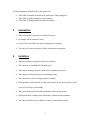
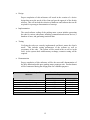
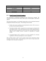
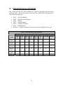
1
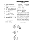
Prototype Parking Metering System—Phase 2
Project Plan
Team Code
:
DEC 04-02
Client
:
Doug Houghton
Captain
Department of Public Safety
Iowa State University
Advisors
:
Prof. John Lamont, EE/CprE
Prof. Ralph Patterson III, EE/CprE
Team Members
:
Joe Reinsma
John Goldbach
Andrew Ross
Mikel Bezdek
Irsan Halim
Date of Submission
:
30 March 2004
Table of Contents
List of Figures
List of Tables
List of Symbols and Definitions
Abstract
Acknowledgement
ii
iii
iv
vii
viii
1.
2.
3.
4.
5.
6.
7.
8.
Problem Statement
Operating Environment
Intended Users
Intended Users
Assumptions
Limitations
Expected End Product and Other Deliverables
Proposed Approach
8.1 Functional Requirements
8.2 Constraints Considerations
8.3 Technology Considerations
8.4 Technical Approach Considerations
8.5 Testing Requirements Considerations
8.6 Security Considerations
8.7 Safety Considerations
8.8 Intellectual Property Considerations
8.9 Commercialization Considerations
8.10 Possible Risk and Risk Management
8.11 Proposed Milestones and Evaluation Criteria
8.12 Project Tracking Procedures
9. Statement of Work
9.1 Task 1 – Problem definition
9.2 Task 2 – Research and technology
9.3 Task 3 – Design
9.4 Task 4 – Implementation
9.5 Task 5 – Testing
9.6 Task 6 – Demonstration
10. Estimated Resource Requirements
11. Schedules
12. Project Team Information
13. Closing Summary
14. References
i
1
2
2
2
3
3
5
6
6
6
8
9
9
10
10
10
10
10
11
13
14
14
14
14
15
15
15
16
19
21
22
22
List of Figures
Figure 1 : Gantt Chart – Project tasks and subtasks
19
Figure 2 : Gantt Chart – Project deliverables
19
ii
List of Tables
Table 1 : Project milestones and importance
11
Table 2 : Milestone evaluation
11
Table 3 : Personnel effort requirements
15
Table 4 : Other resource requirements
16
Table 5 : Financial requirements
17
iii
List of Symbols and Definitions
A
Assembly language
A low-level computer language that consists of mnemonic codes and symbolic
addresses corresponding to machine-language instructions
B
C
C
A high-level object-oriented programming language
C#
An object-oriented programming language based on the design principles of Java
D
E
F
G
H
J
Java
A high-level object-oriented programming language that allows small application
programs to be downloaded from a server to a client along with the data that each
program processes (developed by Sun Microsystems)
K
L
LCD
Liquid crystal display, a low-power digital display that uses liquid crystal cells
that change reflectivity in an applied electronic field
iv
M
Motherboard
For this project, it is a main circuit board of the embedded computer through
which all signals are directed.
MySQL
MySQL is a fast-relational database manager. A database manager enables
adding, retrieving, and processing information stored in a database. The relational
aspect of MySQL means that data is stored in separate tables rather than one large
table. Relations between each table can be established and information can be
retrieved using structured query language (SQL).
N
O
P
Q
R
RAM
Random-Access Memory, the primary working memory in a computer used for
the temporary storage of programs and data and in which the data can be accessed
directly and modified
S
SQL
A standardized language that approximates the structure of natural English for
obtaining information from databases
T
U
USB
Universal Serial Bus, a plug-and-play interface between a computer and
peripheral devices, such as printers, modems, and keyboards
v
V
Visual Basic
A programming language and environment developed by Microsoft based on the
BASIC language using graphical programming environment and a paint metaphor
for developing user interfaces.
W
Wired Ethernet
A trademark for a system for exchanging messages between computers on a local
area network using wired coaxial, fiber optic, or twisted-pair cables
X
Y
Z
vi
Abstract
There are several pay-for-parking lots on the Iowa State campus managed by the
Department of Public Safety (DPS). Currently, two of these lots are controlled by multispace parking meter systems located near the lots. Several undesirable aspects of these
units have left DPS searching for a better solution. This project will provide a solution
by developing a multi-space meter system that provides the same functionalities as the
current units, as well as adding new functions. The developed system will be more costeffective, will be easier to use for people parking in the lots, and will make management
of the lots more straightforward and more effective for DPS. This will make for a better
experience for those using the system and will allow DPS to focus resources on other
more pressing issues.
vii
Acknowledgement
The team would like to acknowledge the following people for their contributions, both
financially and intellectually, to the project: Doug Houghton, Captain, Department of
Public Safety, Iowa State University. We would also like to thank the course instructor
and project advisors, Dr. John W. Lamont and Professor Ralph Patterson III, for their
guidance and advice regarding the project.
viii
1.
Problem Statement
The following sections will provide a general overview of the problem that this project
seeks to address, as well as the proposed method of solving it.
1.1
General Problem Statement
At Iowa State University, as at other colleges around the United States, many issues arise
concerning the availability of parking on or near campus. This has led to the
development of several pay-for-parking lots on the Iowa State campus. Currently, use of
these lots is controlled through centralized units that are able to monitor multiple spaces
at once. This provides some advantages over traditional parking meters from an
administrative standpoint, e.g. money can be collected at once from a central location.
However, while the current system currently has some benefits, there is still much left to
be desired. The fact that the units cannot communicate with one another means that if a
space is paid for on one machine, time can only be added later to that same exact
machine. Also, when the lot is checked for offenders, each machine must be queried
individually, which increases the time to check the lot. Lastly, this has implications for
robustness. If one unit is disabled, all the data stored there is lost.
Another undesirable aspect of the current system is that the units are very hard to
program. DPS would like to be able to set the hourly rates of the lots, as well as program
in university holidays. In the current system, doing so requires a specialist. This process
is both expensive and time consuming.
The project will be achieved by utilizing the efforts of two teams, May 04-02 and Dec
04-02. May 04-02 will be responsible for the slave units, while Dec 04-02 will be
responsible for the master unit.
1.2
General Solution Approach
The solution proposed by this project is to provide a system to monitor the pay-forparking lots that will have all the benefits of the current system as well as to improve on
its negative aspects. The system will be more user-friendly, more cost-effective, more
durable, and easier to maintain. In this solution, control of the parking lots will be
implemented with several, multi-space, communicating units.
Because the units will be able to communicate, users of the lot may add time via any
machine. Also, DPS will only have to query one machine to receive a complete list of lot
activity. Lastly, this feature, combined with a redundant central processor and memory,
will greatly increase the robustness of the system.
1
The new units will also have easier to use interfaces. This will allow DPS the ability to
easily program in rate changes and holidays. This will also make it easier for people
parking in the lots to utilize the system.
Lastly, the unit will be implemented with standard off the shelf computer hardware. This
will decrease the cost to the University, both in initial cost and in maintenance cost.
2.
Operating Environment
The designed units will be located outdoors, and thus must operate in a large range of
temperatures as well as withstand the rain, snow, and other weather conditions present in
Ames, Iowa. The system will be used on a regular basis, and thus must be designed to
withstand extended use. Lastly, the units will be located on a college campus, and thus
must be resistant to attempts at vandalism.
3.
Intended Users
The users of this system fall into two main groups, users of the lots, and administrators of
the lots.
The first group is made up of the people that park in the lots. This group includes (but is
not limited to):
•
•
•
College students at Iowa State University
Faculty and staff of Iowa State University
Visitors to the Iowa State campus
The second group is made up of those that monitor the parking lots, i.e. the Iowa State
University Department of Public Safety employees.
4.
Intended Uses
The system will have two main categories of uses, separated by the two groups of users
(see above).
For the people who park in the lots, the system will:
•
•
•
Allow parking spaces to be paid for, either by first selecting an amount of time, or
by simply putting money in.
Allow time to be added to any parking space from any unit in that lot.
Provide a hard-copy receipt to the user if desired.
2
For the Department of Public Safety, the system will:
•
•
•
Allow DPS to monitor and enforce the paid usage of the parking lots.
Allow DPS to gather parking lot usage statistics.
Allow DPS to change hourly rates and set holidays.
Assumptions
5.
•
The lot size will be equal to or less than 1000 spaces.
•
No change will be returned to users.
•
Power will be provided to the units, excepting power outages.
•
The units will accept only dimes, nickels, and quarters as payment.
6.
Limitations
•
The time available to complete the project is limited.
•
The unit must be weatherproof and theft-proof.
•
The main processing unit must consist of two redundant processors.
•
The main processing unit must have redundant storage.
•
The user interface will be compact and user-friendly.
•
Backup batteries must be able to allow the machine to run for four hours in the
event AC electricity is unavailable.
•
The system must provide all of the capabilities of the current system.
•
DPS must be able to change rates and holidays without outside assistance.
•
The units must allow users to add time to their current amount of time.
3
•
The system must provide information on current stall payment status (paid or
unpaid) for DPS enforcement.
•
The system must accommodate time of day and holiday rates.
•
The unit must have a receipt printer which will print receipts upon request.
4
7.
Expected End Product and Other Deliverables
The end products of this project will be a prototype multi-space parking meter system, a
user manual, and a technical specification. These deliverables are described below:
•
Multi-space parking meter system
The system will consist of a set of units configured to communicate with each
other and able accommodate a lot size of up to 1000 parking spaces. The
master unit will store all of the lot information, and the slave unit(s) will offer
the same user interface but will use data from the master unit. The system
will allow patrons of the lot to pay for parking, and allow DPS to monitor the
usage and enforcement of the lot.
•
User Manual
The user manual will be a document describing the operation of the machines,
in a non-technical manner that can be understood by any user of the system.
These operations described in the manual include monitoring occupancy,
making rate changes, and enforcement functions. A preliminary manual will
be delivered when the system becomes ready for testing, and a final draft will
be delivered in December of 2004.
•
Technical Specification
The technical specification document will be a document describing the
technical specifications of both the hardware and software running on the
master and slave units. This document not designed for common users, but
instead as a resource for future designers of this system. The technical
specification of the system will be delivered in December of 2004.
5
8.
Proposed Approach
This section shall explain the planned method of completing the project.
8.1
Functional Requirements
The following functions shall be required to successfully complete the project.
•
Accepts client input/output
The system will connect to a remote computer using a USB connection.
The system will allow DPS to change hourly rates, time of day rates,
holiday rates, or modify any code that is installed on the master unit.
•
Manages parking space availability
The system will keep track of which parking spaces are currently paid for
and ending time.
•
Communication functionality
The system will allow for communication between interfaces using
Ethernet connection.
8.2
Constraints Considerations
The project shall run with in the following constraints.
•
Weather resistance
The system must be able to withstand all weather conditions an outdoor
system may experience on the Iowa State University campus. These
include extremes of temperature and precipitation as well as severe winds
and associated debris.
•
Durability
The system must be durable, long lasting, and secure. If the unit is built
above ground, it must be able to withstand theft, vandalism, corrosion, and
minor collisions with vehicles. If buried, it must be able to withstand
theft, vandalism, and ground moisture.
6
•
Power requirements
The master/slave system must be run off standard 110 AC power as well
as a battery backup.
•
Hardware requirements
The master system must use a board with redundant processing and
storing capabilities to decrease chances of failure.
•
Connectivity requirements
The master/slave system must be able to complete all necessary
communications over a standardized Ethernet interface.
•
Machine size requirements
The control hardware will be placed inside one of the slave units, so it
must be of a size that facilitates installation, maintenance, and use. The
size of the machine must also be sufficiently large so as to allow for the
inclusion of all necessary internal components.
7
8.3
Technology Considerations
The following technologies shall be considered in the implementation of the end-product.
•
Master system hardware using dual processor-based system
A system of this type utilizing two separate processors would allow for
backing up a processor if one were to fail. It has redundant capability to
store data to two sets of memory. If one processor were to fail, the second
processor would takeover automatically where the other quit. This helps
alleviate downtime so the master control unit can process parking
locations and continue to accept money.
•
Programming language
O
Assembly
The use of assembly would allow for precise control over memory usage
and data handling. It would make for an arduous development process,
however.
O
MySQL
The use of MySQL would allow for easy creation of the central database
and integration with Windows XP operating system.
O C/C#
The use of C/C# would allow for the creation of a modular, robust, and
easily modifiable software product.
O
Visual Basic.Net
The use of Visual Basic.Net would allow for easy graphical user interface.
•
Communications hardware using wired Ethernet
A system of this type would allow for a more reliable communication
medium and much faster than many other available technologies.
8
8.4
Technical Approach Considerations
To successfully create a multiple space parking meter system, two main components will
need to be implemented: the master unit’s hardware and the master unit’s software. The
hardware for the unit must meet the needs of the client. As such, the approach under
consideration involves the use of off the shelf x86 dual processor-based hardware. This
system would use redundant processing and storing technology, designed for the desktop
and server market. A system of this type would allow for increased modularity and
reliability, easier software design and implementation, components of a more
standardized nature, easier maintenance and better expandability.
The unit requires a robust and feature-filled software package. To meet this need, a
technical approach involves the use of C/C# for the creation of software and using
Windows XP as an operating system. This approach would make for a modular, robust,
and easily modified software product. The project team has extensive experience with
this language, so there would be a rapid development process. MySQL is being
considered as a language to create the database and should work well with the Windows
XP operating system.
8.5
Testing Requirements Considerations
The following is a definition of the methodologies and acceptance criteria to be used in
the testing of the intermediate and end-products resulting from this project.
•
Testing of hardware
O The communications hardware needs to be able to operate properly in the
wide range of temperatures and other environmental variables discussed
above, communicating without error and with sufficient speed for the
application.
O The hardware as a whole will be deemed acceptable if it all operates properly
under the aforementioned conditions. If any one type of hardware fails the
tests, alternative hardware must be selected to replace this undesirable
hardware.
•
Testing of software
O The software needs to be tested to ensure that it functions as desired and is
sufficiently robust to withstand daily use.
O The software will be deemed acceptable if it performs all of the desired
functions without error and an uptime of seven days is observed.
9
8.6
Security Considerations
Security is always a concern when dealing with a system involving monetary
transactions. As data will be transmitted across an Ethernet link, an encryption protocol
may be needed. Ethernet was selected over wireless for numerous reasons, one of them
being data security. The end-product must also be physically secure. Physical security
will be in the form of a secure enclosure designed to withstand vandalism, theft, and
collision with a motor vehicle. This enclosure will have locking panels which give access
to the electronic hardware as well as the coin box. To make changes to the rate database
one must have a key for the physical lock and the computer password.
8.7
Safety Considerations
This device poses few safety risks. However, the device does contain electrical
components, so electrical safety must be addressed throughout the design, construction,
and use of the product.
8.8
Intellectual Property Considerations
This project introduces significant differences in design and construction when compared
to similar systems on the market. This should eliminate any trademark infringement
issues. Previous related works that are consulted in the course of this project will be duly
acknowledged. Any intellectual property that results from this project will be the
property of the team members and the Iowa State University Department of Public
Safety.
8.9
Commercialization Considerations
When compared to popular models currently on the market, the system in development
adds features and functionality while drastically decreasing cost. As a result, the
probability of successfully marketing a product based upon the system currently in
development is high.
8.10 Possible Risks and Risk Management
A number of potential risks have been identified:
•
Loss of a team member
In the event a team member is lost, the work assigned to that member will be
redistributed. This risk will be mitigated by implementing a “buddy system”
where at least two members of the group undertake an assigned task.
10
•
Lack of technical expertise
A large loss of productivity may be incurred when team members spend time
gaining familiarity with a new technical aspect. This particular risk is preanticipated and its effects are mitigated by appropriately allocating time.
•
Equipment damage
Unintended damage to project hardware components will take a toll in both
time and replacements costs. This risk will be mitigated by properly handling
and storing all equipment.
•
Inadequate budget
If the amount of funding for the designed project can not be attained, the
original plan will be revised. Solutions could include looking for donations,
removing features, or accepting hardware of lower quality.
•
Equipment availability
Essential hardware may not be available for some unforeseen reason. Many
of the items used are produced in low volume and are not always readily
available. This risk will be mitigated by thoroughly researching hardware
selections. The hardware will be selected as modular as possible, so no one
specific component is irreplaceable.
8.11 Project Proposed Milestones and Evaluation Criteria
•
Project definition
Proper completion of this milestone will be the definition of a problem area,
intended uses and users, design assumptions, limitations and approaches,
project resource requirements, tracking and monitoring procedures, and
evaluation criteria.
•
Research and technology
The information gained by research into the advantages and disadvantages of
hardware and software selections will be used to select a suitable selection of
hardware and software elements to construct the parking meter system.
11
•
Design
Proper completion of this milestone will result in the creation of a device
design that meets the needs of the client and gets the approval of the faculty
advisors. This will include the selection of hardware and software that can be
acquired for a prototype demonstration of concept.
•
Implementation
The actual software coding of the parking meter system includes generating
the code for various subsystems, including communication between devices, a
database of rates, and generating statistical data.
•
Testing
Verifying the code was correctly implemented, and that it meets the client’s
needs. This includes testing performance of the software as well as
correctness of the code. The system will be tested in lab as well as in the
field. As the system deals with monetary exchange, extensive testing will be
required.
•
Demonstration
Proper completion of this milestone will be the successful demonstration of
the fully-functional multi-space parking meter prototype unit. Product demos
will be constructed during the design phase for validation purposes.
Table 1: Project Milestones and Overall Importance
Milestone
Importance
Relative
High
High
Medium
High
Medium
Low
Problem Definition
Research and technology
Design
Implementation
Testing
Demonstration
TOTAL
12
Percentage
21.43
21.43
14.29
21.43
14.29
7.14
100%
Table 2: Milestone Evaluation
Evaluation Result
Numerical Score
Exceeded/Met
100%
Partially met
75%
Did not meet
50%
Did not attempt
0%
8.12 Project Proposed Tracking Procedures
The consistent flow of information regarding the status of the project is essential. The
information will be provided in the form of status reports, schedule updates, and financial
analysis.
The project plan contains a set of planned elements that are to be tracked and monitored
throughout the duration of the project. The tracking activities include:
•
Weekly status reports regarding current and planned activities will be sent out to
the client, advisors and team members.
•
The planned schedule will be compared to the actual progress to determine the
current project status. If the actual progress has not met the planned progress,
steps will be taken to determine the cause of the delay, the impact on the overall
schedule, and to identify corrective measures to compensate for schedule
variance.
•
The planned budget will be compared to the actual expenditure by analyzing
expenditures to date and estimating cost to and at completion.
These tracking measures will be used to provide critical project information without
becoming an excessive burden. Microsoft Project will be used to help automate the
tracking procedures and project management.
13
9.
Statement of Work
The following is a formal statement of work containing a hieratical list of major tasks and
subtasks containing their objectives, approaches, and results.
Task 1 – Problem definition
•
•
•
Objective
Define the problem thoroughly, taking into consideration all possible users, uses,
technological approaches, and design approaches to reduce cost and time.
Approach
Gather complete information about the problem from the client, faculty advisors,
and potential users of the system.
Result
Complete problem definition containing uses, users, assumptions, limitations,
functional requirements, management procedures, and success evaluation criteria.
Task 2 – Research and Technology
•
•
•
Objective
Research, select, and obtain the hardware and software that will best produce
completion of the project.
Approach
Consult sources and professionals to find appropriate hardware and software that
meets functional requirements, cost, robustness, and availability.
Result
Hardware and software will be selected and obtained that meets the project
functional requirements, robustness, has current availability, and is within budget.
Task 3 – Design
•
•
•
Objective
Define and describe the design that will produce the successful end product within
budget and on time.
Approach
Use sound design principles to create a complete and functional design.
Result
A project design that is complete and well defined so that there is no design issues
during its implementation.
14
Task 4 – Implementation
•
•
•
Objective
Implement the project that is described by the design requirements.
Approach
Develop, test, and install software on the assembled hardware given by the design
requirements.
Result
A functioning product that meets the design requirements, specifications and the
clients needs.
Task 5 – Testing
•
•
•
Objective
Verify that the software and hardware works correctly as described by the design
requirements.
Approach
Test all functionality of the software and hardware to make sure there is no failure
that would cause the system to become not functional or in an undefined state.
Result
The system is verified to meet the design requirements.
Task 6 – Demonstration
•
•
•
Objective
Create and perform a demonstration that shows the successful implementation of
the project.
Approach
Examine the needs of the demonstration and plan the demonstration to meet those
needs.
Result
The demonstration will show successful implementation of the project by
showing its functionality and robustness. The demonstration will verify that the
project met all of its requirements.
15
10.
Estimated Resources and Schedule
This section describes the current estimates of resource requirements and the project
schedules. Table 3 shows the projected personnel effort of individual team members for
each of the following tasks:
•
•
•
•
•
•
•
Task 1 — Project definition
Task 2 — Research and technology
Task 3 — Design
Task 4 — Implementation
Task 5 — Testing/verification
Task 6 — Demonstration
Overhead — Weekly meetings, discussions, travel time, and other misc. items
Table 3: Personnel Effort Requirements
Personnel
Name
Joe
Reinsma
Mikel
Bezdek
John
Goldbach
Andrew
Ross
Irsan
Halim
TOTAL
Hours
Task
5
16
Task
1
11
Task
2
12
Task
3
36
Task
4
76
10
10
31
76
17
12
10
34
78
12
10
30
10
10
55
52
Task
6
13
Overhead TOTAL
45
209
12
44
205
16
12
44
206
74
16
12
40
199
29
77
15
12
45
201
160
387
82
61
223
1020
16
Table 4 and Table 5 summarize the estimated financial cost of equipments and other
resource requirements to design a working prototype.
Table 4 : Other Resource Requirements
Item
Motherboard/Processor1
RAM1
Storage1
Motherboard/Processor2
RAM2
Storage2
LCD
Keypad
Misc. Buttons
Printer Controller
Ethernet Switch
UPS Battery Backup Unit
Housing
Project Poster
TOTAL
Team Hours
0
0
0
0
0
0
0
0
0
0
0
0
0
10
10
17
Cost
$150
$50
$200
$150
$50
$200
$75
$100
$50
$120
$57
$100
$100
$50
$1452
Table 5 : Financial Requirements
Item
Cost
Parts and materials
Motherboard/Processor1
RAM1
Storage1
Motherboard/Processor2
RAM2
Storage2
LCD
Keypad
Misc. Buttons
Printer Interface
Ethernet Switch
UPS Battery Backup Unit
Housing
Project Poster
Services
Shipping and handling
Binding
TOTAL (w/o Labor)
$50
$30
$1532
Labor ($10.50 / hour)
Joe Reinsma
Mike Bezdek
John Goldbach
Andrew Ross
Irsan Halim
TOTAL (w/ Labor)
$2331
$2100
$2163
$2037
$2079
$12062
$150
$50
$200
$150
$50
$200
$75
$100
$50
$120
$57
$100
$100
$50
18
11.
Schedule
The following section includes a Gantt chart detailing the projected schedule of tasks.
The illustrated calendar will span the full length of the project, which is two semester
long. The timelines for the various tasks are based on the team’s best estimates of time
requirements, as well as the Senior Design class and deliverable schedules. The team will
adhere to the schedule to the best of its ability in order to keep the project on task.
19
Project Schedule
20
12.
Project Team Information
The following individuals are those directly involved in the definition, development, and
implementation of this project.
Client:
Doug Houghton
Captain
Department of Public Safety
31 Armory Building
Ames, IA 50011
Vox: 515-294-1987
Fax: 515-294-0383
[email protected]
Faculty Advisors:
Professor Ralph Patterson III
326 Town Engineering
Iowa State University
Ames, IA 50010
Vox: 515-294-2428
Fax: 515-294-6790
[email protected]
Dr. John Lamont
324 Town Engineering
Iowa State University
Ames, IA 50010
Vox: 515-294-3600
Fax: 515-294-6760
[email protected]
Team Members:
Joe Reinsma – CprE
530 Welch Ave #10
Ames, IA 500104
952-239-2449
[email protected]
John Goldbach - CprE
225 N. Hyland
Ames, IA 50014
952-237-8565
[email protected]
Andrew Ross – EE
124 N. Franklin
Ames, IA 50014
319-350-9496
[email protected]
Irsan Halim – CprE
632 Squaw Creek #3
Ames, IA 50010
515-441-0389
[email protected]
21
Mikel Bezdek - CprE
1331 Frederickson Court
Ames, IA 50010
515-572-7640
[email protected]
13.
Closing Summary
The need for a powerful and easy to use, yet cost effective solution for managing vehicle
parking on the campus of Iowa State University has never been greater. Solutions
currently available are not feature rich enough, too difficult for easy use, or are too
expensive. It is for these reasons that the University is commissioning the creation of the
multiple space parking meter system described in this document. The system resulting
from the work of this project team will exceed the University’s current needs and will
allow for easy modification in order that it may continue to meet the University’s needs
for years to come. This will result in increased revenues for the University, and will allow
those managing parking to focus on other duties.
14.
References
Prototype Parking Metering System May 04-02
10 February 2004
from http://sd.theotron5000.com/files/designdocument.pdf
22