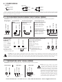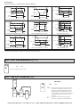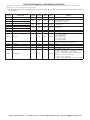
1
LP0890 User Manual PAX2C – 1/8 DIN Temperature/ Process PID Controller With FlexBus™ Phone: 800.894.0412 - Fax: 888.723.4773 - Web: www.the-red-lion.net - Email: [email protected] SAFETY SUMMARY All safety related regulations, local codes and instructions that appear in this literature or on equipment must be observed to ensure personal safety and to prevent damage to either the instrument or equipment connected to it. If equipment is used in a manner not specified by the manufacturer, the protection provided by the equipment may be impaired. Do not use this controller to directly command motors, valves, or other actuators not equipped with safeguards. To do so can be potentially harmful to persons or equipment in the event of a fault to the controller. C UL R CAUTION: Risk of Danger. Read complete instructions prior to installation and operation of the unit. CAUTION: Risk of electric shock. US LISTED 3RSD PROCESS CONTROL EQUIPMENT Warning: Exposed line voltage exists on the circuit boards. Remove all power to the controller and load circuits before accessing inside of the controller. Phone: 800.894.0412 - Fax: 888.723.4773 - Web: www.the-red-lion.net - Email: [email protected] Table Of COnTenTs Ordering Information . . . . . . . . . . . . . . . . . . . . . . . . . . . . . . . . . . . . . . . . . . . . . . . . . . . . . . . .4 Using This Manual . . . . . . . . . . . . . . . . . . . . . . . . . . . . . . . . . . . . . . . . . . . . . . . . . . . . . . . . . .5 Crimson Programming Software . . . . . . . . . . . . . . . . . . . . . . . . . . . . . . . . . . . . . . . . . . . . . . .5 General Controller Specifications. . . . . . . . . . . . . . . . . . . . . . . . . . . . . . . . . . . . . . . . . . . . . . .6 Option Cards . . . . . . . . . . . . . . . . . . . . . . . . . . . . . . . . . . . . . . . . . . . . . . . . . . . . . . . . . . . . . .8 1.0 Installing the Controller . . . . . . . . . . . . . . . . . . . . . . . . . . . . . . . . . . . . . . . . . . . . . . . . . .10 2.0 Setting the Jumpers . . . . . . . . . . . . . . . . . . . . . . . . . . . . . . . . . . . . . . . . . . . . . . . . . . . .10 3.0 Installing Option Cards . . . . . . . . . . . . . . . . . . . . . . . . . . . . . . . . . . . . . . . . . . . . . . . . . . 11 4.0 Wiring the Controller . . . . . . . . . . . . . . . . . . . . . . . . . . . . . . . . . . . . . . . . . . . . . . . . . . . . 11 5.0 Reviewing the Front Buttons and Display. . . . . . . . . . . . . . . . . . . . . . . . . . . . . . . . . . . .13 6.0 Programming The PAX2C. . . . . . . . . . . . . . . . . . . . . . . . . . . . . . . . . . . . . . . . . . . . . . . .14 6.1 Input Programming (INPt) . . . . . . . . . . . . . . . . . . . . . . . . . . . . . . . . . . . . . . . . . . . . . . . .16 6.2 Output Programming (Out) . . . . . . . . . . . . . . . . . . . . . . . . . . . . . . . . . . . . . . . . . . . . . . . .20 6.3 Display Programming (dISP) . . . . . . . . . . . . . . . . . . . . . . . . . . . . . . . . . . . . . . . . . . . . . .23 6.4 PID Programming (Pid) . . . . . . . . . . . . . . . . . . . . . . . . . . . . . . . . . . . . . . . . . . . . . . . . . .31 Operation Overview . . . . . . . . . . . . . . . . . . . . . . . . . . . . . . . . . . . . . . . . . . . . . . . . . . . . . . . .36 Control Mode Explanations . . . . . . . . . . . . . . . . . . . . . . . . . . . . . . . . . . . . . . . . . . . . . . . . . .36 Pid Control Overview . . . . . . . . . . . . . . . . . . . . . . . . . . . . . . . . . . . . . . . . . . . . . . . . . . . . . . .37 Remote Setpoint Control Overview . . . . . . . . . . . . . . . . . . . . . . . . . . . . . . . . . . . . . . . . . . . .38 Auto-Tune Explanations . . . . . . . . . . . . . . . . . . . . . . . . . . . . . . . . . . . . . . . . . . . . . . . . . . . . .40 6.5 Alarm Programming (ALr) . . . . . . . . . . . . . . . . . . . . . . . . . . . . . . . . . . . . . . . . . . . . . . . .42 6.6 Port Programming (Port) . . . . . . . . . . . . . . . . . . . . . . . . . . . . . . . . . . . . . . . . . . . . . . . . .44 Serial Communications Overview . . . . . . . . . . . . . . . . . . . . . . . . . . . . . . . . . . . . . . . . . . . . .46 PAX2C Frequently Used Modbus Registers . . . . . . . . . . . . . . . . . . . . . . . . . . . . . . . . . . . . .47 6.7 Factory Service Operations (FACt) . . . . . . . . . . . . . . . . . . . . . . . . . . . . . . . . . . . . . . . . . .51 7.0 Programming The FlexCard . . . . . . . . . . . . . . . . . . . . . . . . . . . . . . . . . . . . . . . . . . . . . .53 7.1 PX2FCA0 - Process Input FlexCard . . . . . . . . . . . . . . . . . . . . . . . . . . . . . . . . . . . . . . . .53 7.2 PX2FCA1 - Heater Current Input FlexCard . . . . . . . . . . . . . . . . . . . . . . . . . . . . . . . . . .57 Troubleshooting Guide . . . . . . . . . . . . . . . . . . . . . . . . . . . . . . . . . . . . . . . . . . . . . . . . . . . . . .61 Phone: 800.894.0412 - Fax: 888.723.4773 - Web: www.the-red-lion.net - Email: [email protected] Ordering infOrmaTiOn Controller Part Numbers MODEL NO. PAX2C DESCRIPTION PART NUMBER Universal Input Temperature/Process Controller, with FlexBus™, Horizontal PX2C8H00 Universal Input Temperature/Process Controller, with FlexBus™, Vertical PX2C8V00 Option Card and Accessories Part Numbers TYPE MODEL NO. PAXCDS Standard Option Cards PAXCDC PAXCDL FlexBus™ Option Cards PX2FCA Accessory CBLUSB DESCRIPTION PART NUMBER Dual Relay Digital Output Card PAXCDS10 Quad Relay Digital Output Card PAXCDS20 Quad Sinking Open Collector Digital Output Card PAXCDS30 Quad Sourcing Open Collector Digital Output Card PAXCDS40 Dual Triac/Dual SSR Drive Digital Output Card PAXCDS50 Quad Form C Relay Digital Output Card PAXCDS60 * RS485 Serial Communications Card with Terminal Block PAXCDC10 Extended RS485 Serial Communications Card with Dual RJ11 Connector PAXCDC1C RS232 Serial Communications Card with Terminal Block PAXCDC20 Extended RS232 Serial Communications Card with 9 Pin D Connector PAXCDC2C DeviceNet Communications Card PAXCDC30 Profibus-DP Communications Card PAXCDC50 Analog Output Card PAXCDL10 Process Input/Remote Setpoint Input Card, With Digital Outputs PX2FCA00 * Heater Current Monitor Input Card, With Digital Outputs PX2FCA10 * USB Programming Cable Type A-Mini B CBLUSB01 Note: For Modbus communications use an RS485 Communications Output Card and configure communication (tYPE) parameter for Modbus. * This card is not suitable for use in older PAX2C models. For proper installation, 3 case knock-out features must be present on the top case surface (horizontal controller) or right case surface (vertical controller). To update a case to include these knock-outs, a replacement case is available. RCPX2H00 = Horizontal replacement case, RCPX2V00 = Vertical replacement case. Phone: 800.894.0412 - Fax: 888.723.4773 - Web: www.the-red-lion.net - Email: [email protected] Using This manUal This manual contains installation and programming instructions for the PAX2C and all applicable option cards. For ease of installation it is recommended that the Installation Guide received with the controller be used for the installation process. Only the portions of this manual that apply to the application need to be read. Minimally, we recommend that General Controller Specifications, Reviewing the Front Buttons and Display, and Crimson® Programming Software portions of this manual be read in their entirety. We highly recommend that controller programming be performed using Crimson programming software. When using Crimson, the programming portion of this manual serves as an overview of the programming options that are available through Crimson. The programming section of the manual will serve to provide expanded explanations of some of the PAX2C programming features found in Crimson. For users who do not intend to use Crimson to program their controller, this manual includes information to provide for a user to program one, or all, of the programming parameters using the controller’s keypad. Note that due to the extensive programming features of the PAX2C, complete programming of the controller using the controller’s keypad is not recommended. When a FlexCard™ is installed, additional parameters may be available. Unique FlexCard parameters are defined in 7.0 Programming the FlexCard. Parameters identified as FCx that are not defined in the FlexCard programming portion of the manual function as defined in 6.0 Programming the PAX2C. To find information regarding a specific topic or mnemonic, it is recommended that the manual be viewed on a computer and the “find” function be used. The alternate method of finding information is to identify the programming parameter involved (Input, Output, Display, PID, Alarm, or Communication) and review the information contained in the section of the manual that pertains to that parameter. CrimsOn PrOgramming sOfTware Crimson® software is a Windows® based program that allows configuration of the PAX® controller from a PC. Crimson offers standard drop-down menu commands, that make it easy to program the controller. The controller’s program can then be saved in a PC file for future use. PrOgramming Using CrimsOn: Crimson is included on the Flash Drive that is shipped with the PAX2C. Check for updates to Crimson at Red Lion website - Install Crimson. Follow the installation instructions provided by the source from which Crimson is being downloaded or installed. - Using a USB Type A-Mini B cable, plug the Mini B end of the cable into the PAX2C USB Programming Port. - Plug the other end of the USB cable into an available USB port on the PC. - Apply power to the PAX2C. If a FlexCard has been removed, or has had the address changed, error message(s) will need to be resolved before continuing. See Troubleshooting, on page 61, for error message resolution. - Start Crimson. - Click the Crimson “Link” tab. - Click “Extract…” o Crimson will extract the current program settings from the PAX2C. o If the controller has not been programmed, the extracted file will contain factory settings. Note that the PAX2C factory settings vary based on the option cards installed. o Crimson will display a PAX2C with various areas described by the programming parameters that pertain to the area. - Double click on the “Analog/User Inputs/F Keys/PID” area. - Make configuration selections. For information regarding a configuration selection, hover the curser over the selection area. - Make configuration selections for each tab that appears across the top. When completed click “Close”. - Repeat the configuration selection process for the Display/Alarm Parameters area, followed by applicable option card programming areas. - When all programming selections have been made, save the configuration file. - Download the configuration file to the PAX2C by clicking the “Link” tab and selecting “Update”. USB Programming Port Phone: 800.894.0412 - Fax: 888.723.4773 - Web: www.the-red-lion.net - Email: [email protected] general COnTrOller sPeCifiCaTiOns 1. DISPLAY: Negative image LCD with tri-color backlight. The display is divided into seven independently programmable color zones: Line 1, Line 2, Universal Annunciators (1-4) & Status Mnemonics Line 1 and 2: 4 digits each line Display Range: -1999 to 9999 Units - Programmable 3 digit units annunciator Bar Graph - Programmable 8 segment bar graph Universal Annunciator 1 thru 4: Programmable 2 digit annunciator Status Mnemonics: MAN - Controller is in Manual Control Mode REM – Controller is in Remote Setpoint Mode Vertical Model Digit Size: Line 1 - 0.51" (13 mm), Line 2 - 0.44" (11.2 mm) Horizontal Model Digit Size: Line 1 - 0.62" (15.7 mm), Line 2 - 0.47" (12.0 mm) 2. POWER: AC Power: 40 to 250 VAC, 50/60 Hz, 20 VA DC Power: 21.6 to 250 VDC, 8 W Isolation: 2300 Vrms for 1 min. to all inputs and outputs. 3. KEYPAD: 2 programmable function keys, 4 keys total 4. A/D CONVERTER: 24 bit resolution 5. DISPLAY MESSAGES: “OLOL” - Appears when measurement exceeds + signal range. “ULUL” - Appears when measurement exceeds - signal range “Shrt” - Appears when shorted sensor is detected. (RTD range only) “OPEN” - Appears when open sensor is detected. (TC/RTD range only) “. . . . ” - Appears when display values exceed + display range. “- . . . ” - Appears when display values exceed - display range. 6. INPUT CAPABILITIES: Current Input: Temperature Inputs: Scale: °F or °C Offset Range: -1999 to 9999 display units. Thermocouple Inputs: Input Impedance: 20MW Lead Resisitance Effect: 0.03 µV/W Max Continuous Overvoltage: 30 VDC INPUT TYPE WIRE COLOR ACCURACY* ACCURACY* STANDARD (18 to 28 °C) (0 to 50 °C) RANGE ANSI BS 1843 T -200 to 400°C 1.2°C 2.1°C ITS-90 (+) blue (-) red (+) white (-) blue E -200 to 750°C 1.0°C 2.4°C ITS-90 (+) purple (+) brown (-) red (-) blue J -200 to 760°C 1.1°C 2.3°C ITS-90 (+) white (-) red K -200 to 1250°C 1.3°C 3.4°C ITS-90 (+) yellow (+) brown (-) red (-) blue R 0 to 1768°C 1.9°C 4.0°C ITS-90 no standard (+) white (-) blue S 0 to 1768°C 1.9°C 4.0°C ITS-90 no standard (+) white (-) blue B 150 to 300°C 300 to 1820°C 3.9°C 2.8°C 5.7°C 4.4°C ITS-90 no standard no standard N -200 to 1300°C 1.3°C 3.1°C ITS-90 (+) orange (+) orange (-) red (-) blue C (W5/W26) 0 to 2315°C 1.9°C 6.1°C ASTM no E988-90** standard (+) yellow (-) blue no standard INPUT RANGE ACCURACY * (18 to 28°C) ACCURACY * (0 to 50°C) IMPEDANCE ‡ RESOLUTION ± 250 µADC 0.03% of rdg + 0.03µA 0.12% of rdg + 0.04µA 1.11 KW 0.1µA ± 2.5 mADC 0.03% of rdg + 0.3µA 0.12% of rdg + 0.4µA 111 W 1µA ± 25 mADC 0.03% of rdg + 3µA 0.12% of rdg + 4µA 11.1 W 10µA ± 250 mADC 0.05% of rdg + 30µA 0.12% of rdg + 40µA 1.1 W 0.1mA INPUT TYPE RANGE ACCURACY* (18 to 28 °C) ACCURACY* (0 to 50 °C) STANDARD ** ± 2 ADC 0.5% of rdg + 0.3mA 0.7% of rdg + 0.4mA 0.1 W 1mA 100 ohm Pt alpha = .00385 -200 to 850°C 0.4°C 1.6°C IEC 751 100 ohm Pt alpha = .00392 -200 to 850°C 0.4°C 1.6°C no official standard 120 ohm Nickel alpha = .00672 -80 to 259°C 0.2°C 0.5°C no official standard 10 ohm Copper alpha = .00427 -110 to 260°C 0.4°C 0.9°C no official standard RTD Inputs: Type: 3 or 4 wire, 2 wire can be compensated for lead wire resistance Excitation current: 100 ohm range: 136.5 µA ±10% 10 ohm range: 2.05 mA ±10% Lead resistance: 100 ohm range: 10 ohm/lead max. 10 ohm range: 3 ohms/lead max. Max. continuous overload: 30 VDC Voltage Input: INPUT RANGE ACCURACY * (18 to 28°C) ACCURACY * (0 to 50°C) IMPEDANCE ‡ RESOLUTION ± 250 mVDC 0.03% of rdg + 30µV 0.12% of rdg + 40µV 451 KW 0.1mV ± 2.0 VDC 0.03% of rdg + 0.3mV 0.12% of rdg + 0.4mV 451 KW 1mV ± 10 VDC 0.03% of rdg + 3mV 0.12% of rdg + 4mV 451 KW 1mV ± 25 VDC 0.03% of rdg + 3mV 0.12% of rdg + 4mV 451 KW 10mV ± 100 VDC 0.3% of rdg + 30mV 0.12% of rdg + 40mV 451 KW 0.1V ± 200 VDC 0.3% of rdg + 30mV 0.12% of rdg + 40mV 451 KW 0.1V Resistance Inputs: INPUT RANGE 0.05% of rdg 0.2% of rdg +0.03 ohm +0.04 ohm 0.175 V 30 V 0.1 ohm 0.05% of rdg 0.2% of rdg 999 ohm +0.3 ohm +0.4 ohm 1.75 V 30 V 1 ohm 0.05% of rdg 0.2% of rdg +1 ohm +1.5 ohm 17.5 V 30 V 1 ohm 100 ohm 9999 ohm ‡ MAX CONT. ‡ ACCURACY * ACCURACY * COMPLIANCE OVERLOAD RESOLUTION (18 to 28°C) (0 to 50°C) Higher resolution can be achieved via input scaling. * After 20 min. warm-up, @ 5 samples per second input update rate. Accuracy is specified in two ways: Accuracy over an 18 to 28ºC and 15 to 75% RH environment; and Accuracy over a 0 to 50ºC and 0 to 85% RH (non condensing) environment. The specification includes the A/D conversion errors, linearization conformity, and thermocouple ice point compensation. Total system accuracy is the sum of controller and probe errors. Accuracy may be improved by field calibrating the controller readout at the temperature of interest. ** These curves have been corrected to ITS-90. Phone: 800.894.0412 - Fax: 888.723.4773 - Web: www.the-red-lion.net - Email: [email protected] 7. EXCITATION POWER: Jumper selectable Transmitter Power: +18 VDC, ± 5% @ 50 mA max. Reference Voltage: + 2 VDC, ± 2% Compliance: 1KW load min (2 mA max) Temperature Coefficient: 40 ppm/ºC max. Reference Current: 1.05 mADC, ± 2% Compliance: 10 KW load max. Temperature Coefficient: 40 ppm/ºC max. 8. USER INPUTS: Two programmable user inputs Max. Continuous Input: 30 VDC Isolation To Sensor Input Common: Not isolated. Logic State: User programmable (UACt) for sink/source (Lo/Hi) INPUT STATE (USrACt) SINK (Lo ) SOURCE (Hi ) 20KW pull-up to +3.3V 20KW pull-down Active VIN < 1.1 VDC VIN > 2.2 VDC Inactive VIN > 2.2 VDC VIN < 1.1 VDC 9. CUSTOM LINEARIZATION: Data Point Pairs: Selectable from 2 to 16 Display Range: -1999 to 9999 Decimal Point: 0 to 0.000 10. MEMORY: Nonvolatile FRAM memory retains all programmable parameters and display values. 11. ENVIRONMENTAL CONDITIONS: Operating Temperature Range: 0 to 50 °C Storage Temperature Range: -40 to 60 °C Vibration to IEC 68-2-6: Operational 5-150 Hz, 2 g Shock to IEC 68-2-27: Operational 25 g (10 g relay) Operating and Storage Humidity: 0 to 85% max. RH non-condensing Altitude: Up to 2000 meters 12. CERTIFICATIONS AND COMPLIANCES: CE Approved EN 61326-1 Immunity to Industrial Locations Emission CISPR 11 Class A IEC/EN 61010-1 RoHS Compliant UL Listed: File #E179259 Type 4X Indoor Enclosure rating (Face only) IP65 Enclosure rating (Face only) IP20 Enclosure rating (Rear of unit) Refer to EMC Installation Guidelines section of the bulletin for additional information. 13. CONNECTIONS: High compression cage-clamp terminal block Wire Strip Length: 0.3" (7.5 mm) Wire Gauge Capacity: 26 to 16 AWG (0.14 to 1.5 mm2) Torque: 4.4-5.3 inch-lbs (0.5-0.6 N-m) 14. CONSTRUCTION: This controller is rated NEMA 4X/IP65 for indoor use only. IP20 Touch safe. Installation Category II, Pollution Degree 2. One piece bezel/case. Flame resistant. Synthetic rubber keypad. Panel gasket and mounting clip included. 15. WEIGHT: 8 oz. (226.8 g) DIMENSIONS In inches (mm) 3.80 (96.52) 1.95 (49.53) 0.10 (2.54) 4.14 (105.16) 3.60 (91.44) Note: To determine dimensions for horizontal controllers, swap height and width. Recommended minimum clearance (behind the panel) for mounting clip installation is: 2.1" (53.4) W x 5.5" (140) H. 1.75 (44.45) Phone: 800.894.0412 - Fax: 888.723.4773 - Web: www.the-red-lion.net - Email: [email protected] OPTiOn Cards WARNING: Disconnect all power to the controller before installing option cards. Adding Option Cards The PAX2C controller can be fitted with up to three option cards. FlexCard™ option cards can be placed in any of the three available PAX2C option card slots and allows for multiple, and duplicate (2 max) FlexCards to be used in a single controller. Standard option cards require that the option card be placed in a specific PAX2C option card slot. Standard option card use is also limited to only one option card for each function type. The function types include Setpoint/ Control (PAXCDS), Communications (PAXCDC), and Analog Output (PAXCDL). Option cards can be installed initially or at a later date. ANALOG INPUT FLEXCARDS (PX2FCA) Analog Input FlexCard option cards can be placed in any of the three available PAX2C option card slots and allow for multiple, and duplicate (2 max) FlexCards to be used in a single controller. BOTH ANALOG INPUT FLEXCARDS Output Specifications: Four Solid-State NFET outputs Type: Switched DC, N Channel open drain MOSFET Current Rating: 1 A DC max VDS ON: < 0.2 V @ 1 A VDS Max: 30 VDC Offstate Leakage Current: 0.5 µA max. Output Power Supply (+Vout): 18 to 25 VDC @ 40 mA maximum. Connections: High compression cage-clamp terminal block (rear terminal block) Wire Strip Length: 0.3" (7.5 mm) Wire Gauge Capacity: 26 to 16 AWG (0.14 to 1.5 mm2) Torque: 4.4-5.3 inch-lbs (0.5-0.6 N-m) Spring-cage-clamp terminal block (top terminal block) Wire Strip Length: 0.28" (7 mm) Wire Gauge Capacity: 24-16 AWG (0.2-1.5 mm2) PROCESS INPUT/REMOTE SETPOINT CARD: PX2FCA00 Note: A maximum of two Process Input/Remote Setpoint cards can be installed in a PAX2C. Input Ranges: 0 to 10 VDC, 0 to 20 mA DC A/D Conversion: 16 bit, 6.8 samples/second Input Specifications: INPUT RANGE 10 V 20 mA ACCURACY @ 0-50°C 0.1% of span 0.1% of span INPUT IMPEDANCE 538 KΩ 10 Ω MAX INPUT SIGNAL 30 V 150 mA HEATER CURRENT MONITOR CARD: PX2FCA10 A/D Conversion: 16 bit, 6.8 samples/second Input Specifications: Type: Single phase, full wave monitoring of load currents Input: 100 mA AC output from current transformer (RLC p/n CT005001 or equiv.) Input Resistance: 5 Ω Accuracy: ±1.0% full scale, 5 to 100% of range Frequency: 50 to 400 Hz Overload: 200 mA (continuous) Output on time delay for break alarm: 1 second COMMUNICATION CARDS (PAXCDC) A variety of communication protocols are available for the PAX2C controller. Only one PAXCDC card can be installed at a time. Note: For Modbus communications use RS485 Communications Output Card and configure communication (tYPE) parameter for Modbus. SERIAL COMMUNICATIONS CARD: PAXCDC1_ and PAXCDC2_ Type: RS485 or RS232 Communication Type: Modbus ASCII, RLC Protocol (ASCII), and Modbus RTU Isolation To Sensor & User Input Commons: 500 Vrms for 1 min. Not Isolated from all other commons. Data: 7/8 bits Baud: 1200 to 38,400 Parity: no, odd or even Bus Address: Selectable 0 to 99 (RLC Protocol), or 1 to 247 (Modbus Protocol), Max. 32 controllers per line (RS485) Transmit Delay: Selectable for 0 to 0.250 sec (+2 msec min) DEVICENET™ CARD: PAXCDC30 Compatibility: Group 2 Server Only, not UCMM capable Baud Rates: 125 Kbaud, 250 Kbaud, and 500 Kbaud Bus Interface: Phillips 82C250 or equivalent with MIS wiring protection per DeviceNet™ Volume I Section 10.2.2. Node Isolation: Bus powered, isolated node Host Isolation: 500 Vrms for 1 minute between DeviceNet™ and controller input common. PROFIBUS-DP CARD: PAXCDC50 Fieldbus Type: Profibus-DP as per EN 50170, implemented with Siemens SPC3 ASIC Conformance: PNO Certified Profibus-DP Slave Device Baud Rates: Automatic baud rate detection in the range 9.6 Kbaud to 12 Mbaud Station Address: 0 to 125, set by rotary switches. Connection: 9-pin Female D-Sub connector Network Isolation: 500 Vrms for 1 minute between Profibus network and sensor and user input commons. Not isolated from all other commons. DIGITAL OUTPUT CARDS (PAXCDS) The PAX2C controller has 6 available digital output option cards. Only one PAXCDS card can be installed at a time. (Logic state of the outputs can be reversed in the programming.) These option cards include: DUAL RELAY CARD: PAXCDS10 Type: Two FORM-C relays Isolation To Sensor & User Input Commons: 2000 Vrms for 1 min. Contact Rating: One Relay Energized: 5 amps @ 120/240 VAC or 28 VDC (resistive load). Total current with both relays energized not to exceed 5 amps Life Expectancy: 100 K cycles min. at full load rating. External RC snubber extends relay life for operation with inductive loads QUAD RELAY CARD: PAXCDS20 Type: Four FORM-A relays Isolation To Sensor & User Input Commons: 2300 Vrms for 1 min. Contact Rating: One Relay Energized: 3 amps @ 240 VAC or 30 VDC (resistive load). Total current with all four relays energized not to exceed 4 amps Life Expectancy: 100K cycles min. at full load rating. External RC snubber extends relay life for operation with inductive loads QUAD SINKING OPEN COLLECTOR CARD: PAXCDS30 Type: Four isolated sinking NPN transistors. Isolation To Sensor & User Input Commons: 500 Vrms for 1 min. Not Isolated from all other commons. Rating: 100 mA max @ VSAT = 0.7 V max. VMAX = 30 V QUAD SOURCING OPEN COLLECTOR CARD: PAXCDS40 Type: Four isolated sourcing PNP transistors. Isolation To Sensor & User Input Commons: 500 Vrms for 1 min. Not Isolated from all other commons. Rating: Internal supply: 18 VDC unregulated, 30 mA max. total External supply: 30 VDC max., 100 mA max. each output Phone: 800.894.0412 - Fax: 888.723.4773 - Web: www.the-red-lion.net - Email: [email protected] DUAL TRIAC/DUAL SSR DRIVE CARD: PAXCDS50 Triac: Type: Isolated, zero crossing detection Voltage: 260 VAC max., 20 VAC min. Max Load Current: 1 Amp @ 25°C 0.75 Amp @ 50°C Total load current with both triacs ON not to exceed 1.5 Amps Min Load Current: 5 mA Off State Leakage Current: 1 mA max @ 60 Hz Operating Frequency: 20-400 Hz SSR Drive: Type: Two isolated sourcing PNP Transistors. Isolation To Sensor & User Input Commons: 500 Vrms for 1 min. Not Isolated from all other commons. Rating: Output Voltage: 18/24 VDC (unit dependent) ± 10%, 30 mA max. total both outputs LINEAR DC OUTPUT CARD (PAXCDL) Either a 0/4-20 mA or 0-10 V linear DC output is available from the analog output option card. The programmable output low and high scaling can be based on various display values. Reverse slope output is possible by reversing the scaling point positions. ANALOG OUTPUT CARD: PAXCDL10 Types: 0 to 20 mA, 4 to 20 mA or 0 to 10 VDC Isolation To Sensor & User Input Commons: 500 Vrms for 1 min. Not Isolated from all other commons. Accuracy: 0.17% of FS (18 to 28 °C); 0.4% of FS (0 to 50 °C) Resolution: 1/3500 Compliance: 10 VDC: 10 KW load min., 20 mA: 500 W load max. Powered: Self-powered QUAD FORM C RELAY CARD: PAXCDS60 Type: Four FORM-C relays Isolation To Sensor & User Input Commons: 500 Vrms for 1 min. Contact Rating: Rated Load: 3 Amp @ 30 VDC/125 VAC Total Current With All Four Relays Energized not to exceed 4 amps Life Expectancy: 100 K cycles min. at full load rating. External RC snubber extends relay life for operation with inductive loads Phone: 800.894.0412 - Fax: 888.723.4773 - Web: www.the-red-lion.net - Email: [email protected] 1.0 insTalling The COnTrOller INSTALLATION The PAX2C meets NEMA 4X/IP65 requirements when properly installed. The controller is intended to be mounted into an enclosed panel. Prepare the panel cutout to the dimensions shown. Remove the panel latch from the controller. Slide the panel gasket over the rear of the controller to the back of the bezel. The controller should be installed fully assembled. Insert the controller into the panel cutout. While holding the controller in place, push the panel latch over the rear of the controller so that the tabs of the panel latch engage in the slots on the case. The panel latch should be engaged in the farthest forward slot possible. To achieve a proper seal, tighten the latch screws evenly until PANEL the controller is snug in the panel (Torque to approximately 7 in-lbs [79NBEZEL cm]). Do not over-tighten the screws. LATCHING SLOTS INSTALLATION ENVIRONMENT The controller should be installed in a location that does not exceed the operating temperature and provides good air circulation. Placing the controller near devices that generate excessive heat should be avoided. The bezel should only be cleaned with a soft cloth and neutral soap product. Do NOT use solvents. Continuous exposure to direct sunlight may accelerate the aging process of the bezel. Do not use tools of any kind (screwdrivers, pens, pencils, etc.) to operate the keypad of the controller. 1.77+.02 -.00 (45 +.5 -.0 ) 3.62 +.03 -.00 (92 +.8 -.0 ) 1.77+.02 -.00 (45 +.5 -.0 ) PANEL LATCH 3.62 +.03 -.00 (92 +.8 -.0 ) LATCHING TABS HORIZONTAL PANEL CUT-OUT PANEL GASKET PANEL MOUNTING SCREWS 2.0 seTTing The VERTICAL PANEL CUT-OUT JUmPers The PAX2C controller has four jumpers that must be checked and/or changed prior to applying power. The following Jumper Selection Figures show an enlargement of the jumper area. To access the jumpers, remove the controller base from the case by firmly squeezing and pulling back on the side rear finger tabs. This should lower the latch below the case slot (which is located just in front of the finger tabs). It is recommended to release the latch on one side, then start the other side latch. Warning: Exposed line voltage exists on the circuit boards. Remove all power to the controller and load circuits before accessing inside of the controller. Current Input For current input, only one jumper must be configured to select the current range. This jumper is shared with the voltage input range. To avoid overloads, select the jumper position that is high enough to accommodate the maximum signal input level to be applied. Note: The position of the T/V jumper does not matter when the controller is in the current input mode. Temperature Input For temperature measurement the T/V jumper must be in the T (temperature) position. For RTD sensors the RTD jumper must also be set. Resistance Input FRONT DISPLAY Three jumpers are used to configure the resistance input. The T/V jumper must be in the V (voltage) position, and the excitation jumper must be in the 1.05 mA REF position. The voltage/resistance jumper position is determined by the input range. Main Circuit Board Excitation Output Jumper This jumper is used to select the excitation range for the application. If excitation is not being used, it is not necessary to check or move this jumper. EXCITATION OUTPUT JUMPER VEXC Finger Tab RTD 18V @ 50mA 2V REF. 1.05 mA REF. 100 JUMPER LOCATIONS T I V Finger Tab 10 ohm RTD 100 ohm RTD V RTD INPUTS INPUT RANGE JUMPERS REAR TERMINALS INPUT RANGE JUMPERS Voltage Input Two jumpers are used in configuring the controller for voltage/resistance. The first jumper, T/V, must be in the V (voltage) position. The second jumper is used to select the proper voltage input range. (This jumper is also used to select the current input range.) Select a range that is high enough to accommodate the maximum signal input to avoid overloads. For proper operation, the input range selected in programming must match the jumper setting. 2A 250 mA 25 mA 2.5 mA 250 µA THERMOCOUPLE/ VOLTAGE SELECTION TEMPERATURE VOLTAGE CURRENT INPUTS LV - 250mV/2V/100Ω/1KΩ M - 10V/100V HV - 25V/200V/10KΩ VOLTAGE/RESISTANCE INPUTS REAR TERMINALS Phone: 800.894.0412 - Fax: 888.723.4773 - Web: www.the-red-lion.net - Email: [email protected] 3.0 insTalling OPTiOn Cards The option cards are separately purchased optional cards that perform specific functions. These cards plug into the main circuit board of the controller. The option cards have many unique functions when used with the PAX2C. CAUTION: The option and main circuit boards contain static sensitive components. Before handling the cards, discharge static charges from your body by touching a grounded bare metal object. Ideally, handle the circuit boards at a static controlled clean workstation. Dirt, oil or other contaminants that may contact the circuit boards can adversely affect circuit operation. Alignment Slots TOP VIEW FlexCard Connectors Main Circuit Board Analog Output Card Standard Card Connectors Setpoint Output Card Serial Communications Card Finger Tab Slot # 1 2 4.0 wiring 3 The Finger Tab To Install: 1. For option card specific installation instructions, see the installation instructions provided with the option card being installed. 2. When handling the main circuit board, hold it by the rear cover. When handling the option card, hold it by the terminal block. 3. Remove the main assembly from the rear of the case by squeezing both finger holds on the rear cover and pulling the assembly out of the case. Or use a small screwdriver to depress the side latches and pull the main assembly out of the case. Do not remove the rear cover from the main circuit board. 4. Locate the appropriate option card slot location on the main circuit board. Align the option card terminal block with the slot terminal block position on the rear cover. Align the option card connector with the main circuit board option card connector and then press to fully engage the connector. Verify the tab on the option card rests in the alignment slot on the display board. 5. If installing an option card that includes a terminal block on the top of the option card, a knock-out on the top of the PAX case will need to be removed to allow the top terminal block to be inserted later. Locate the shaped knock-out that aligns with the option slot for which the option card is being installed. Carefully remove the knock-out, being careful not to remove additional knock-outs. Trim knock-out tabs (gates) that remain on the case. The top terminal block on the option card will need to be removed before completing step 6. 6. Slide the assembly back into the case. Be sure the rear cover latches engage in the case. If option card includes a top terminal block, install top terminal block at this time. COnTrOller WIRING OVERVIEW Electrical connections are made via terminals located on the back or top of the controller. All conductors should conform to the controller’s voltage and current ratings. All cabling should conform to appropriate standards of good installation, local codes and regulations. It is recommended that the power supplied to the controller (DC or AC) be protected by a fuse or circuit breaker. When wiring the controller, compare the numbers embossed on the back of the controller case to those shown in wiring drawings for proper wire position. Strip the wire, according to the terminal block specifications (stranded wires should be tinned with solder). Insert the lead into the correct terminal and then tighten the terminal until the wire is secure (Pull wire to verify tightness). EMC INSTALLATION GUIDELINES WARNING: Exposed line voltage will be present on the circuit boards when power is applied. Remove all power to the controller AND load circuits before accessing the controller. Although Red Lion Controls Products are designed with a high degree of immunity to Electromagnetic Interference (EMI), proper installation and wiring methods must be followed to ensure compatibility in each application. The type of the electrical noise, source or coupling method into a unit may be different for various installations. Cable length, routing, and shield termination are very important and can mean the difference between a successful or troublesome installation. Listed are some EMI guidelines for a successful installation in an industrial environment. 1. A unit should be mounted in a metal enclosure, which is properly connected to protective earth. 2. Use shielded cables for all Signal and Control inputs. The shield connection should be made as short as possible. The connection point for the shield depends somewhat upon the application. Listed below are the recommended methods of connecting the shield, in order of their effectiveness. a. Connect the shield to earth ground (protective earth) at one end where the unit is mounted. b. Connect the shield to earth ground at both ends of the cable, usually when the noise source frequency is over 1 MHz. 3. Never run Signal or Control cables in the same conduit or raceway with AC power lines, conductors, feeding motors, solenoids, SCR controls, and heaters, etc. The cables should be run through metal conduit that is properly grounded. This is especially useful in applications where cable runs are long and portable two-way radios are used in close proximity or if the installation is near a commercial radio transmitter. Also, Signal or Control cables within an enclosure should be routed as far away as possible from contactors, control relays, transformers, and other noisy components. 4. Long cable runs are more susceptible to EMI pickup than short cable runs. 5. In extremely high EMI environments, the use of external EMI suppression devices such as Ferrite Suppression Cores for signal and control cables is effective. The following EMI suppression devices (or equivalent) are recommended: Fair-Rite part number 0443167251 (RLC part number FCOR0000) Line Filters for input power cables: Schaffner # FN2010-1/07 (Red Lion Controls # LFIL0000) 6. To protect relay contacts that control inductive loads and to minimize radiated and conducted noise (EMI), some type of contact protection network is normally installed across the load, the contacts or both. The most effective location is across the load. a. Using a snubber, which is a resistor-capacitor (RC) network or metal oxide varistor (MOV) across an AC inductive load is very effective at reducing EMI and increasing relay contact life. b. If a DC inductive load (such as a DC relay coil) is controlled by a transistor switch, care must be taken not to exceed the breakdown voltage of the transistor when the load is switched. One of the most effective ways is to place a diode across the inductive load. Most RLC products with solid state outputs have internal zener diode protection. However external diode protection at the load is always a good design practice to limit EMI. Although the use of a snubber or varistor could be used. RLC part numbers: Snubber: SNUB0000 Varistor: ILS11500 or ILS23000 7. Care should be taken when connecting input and output devices to the instrument. When a separate input and output common is provided, they should not be mixed. Therefore a sensor common should NOT be connected to an output common. This would cause EMI on the sensitive input common, which could affect the instrument’s operation. Visit RLC’s web site for more information on EMI guidelines, Safety and CE issues as they relate to Red Lion Controls products. Phone: 800.894.0412 - Fax: 888.723.4773 - Web: www.the-red-lion.net - Email: [email protected] 4.1 POWER WIRING AC Power DC Power 1 AC/DC 2 AC/DC + 1 AC/DC - 2 AC/DC OR - 1 AC/DC + 2 AC/DC The power supplied to the controller shall employ a 15 Amp UL approved circuit breaker for AC input and a 1 Amp, 250 V UL approved fuse for DC input. It shall be easily accessible and marked as a disconnecting device to the installed controller. This device is not directly intended for connection to the mains without a reliable means to reduce transient over-voltages to 1500 V. 4.2 VOLTAGE/RESISTANCE/CURRENT INPUT SIGNAL WIRING IMPORTANT: Before connecting signal wires, the Input Range Jumpers and Excitation Jumper should be verified for proper position. - 2A DC MAX. 7 8 INP COMM 7 8 Iout 3 WIRE TRANSMITTER + Potentiometer Signal as Voltage Input (3 wire requiring excitation) 1.05 mA REF. 10K MAX Terminal 3: High end of pot. Terminal 7: Wiper Terminal 8: Low end of pot. Excitation Jumper: 2 V REF. T/V Jumper: V Voltage/Resistance Input Jumper: 2 Volt Module 1 Input Range: 2 Volt Note: The Apply signal scaling style should be used because the signal will be in volts. _ Vout V-TC-RTD-IN V EXC Terminal 3: Jumper to terminal 7 Terminal 7: Resistance Terminal 8: Resistance 3 Excitation Jumper: 1.05 mA REF. T/V Jumper: V position Voltage/Resistance Input Jumper: Set per input signal 6 V EXC Resistance Signal (2 wire requiring excitation) 3 3 7 2V REF. INP COMM + 2 WIRE TRANSMITTER Terminal 3: +Volt supply Terminal 7: +VDC (signal) Terminal 8: -VDC (common) Excitation Jumper: 18 V V-TC-RTD-IN 6 Voltage Signal (3 wire requiring 18 V excitation) I INPUT Terminal 3: +Volt supply Terminal 6: +ADC (signal) Terminal 8: -ADC (common) Excitation Jumper: 18 V V EXC 3 Load + 200VDC MAX. I INPUT - V EXEC + - • 8 Current Signal (3 wire requiring 18 V excitation) Excitation Jumper: 18 V INP COMM + INP COMM 8 6 Process/Current Signal (2 wire requiring 18V excitation) V-TC-RTD-IN INP COMM 7 Process/Current Signal (external powered) I INPUT V-TC-RTD IN Voltage Signal 8 2V INPUT Rmin=1KΩ CAUTION: Sensor input common is NOT isolated from user input common. In order to maintain safe operation of the controller, the sensor input common must be suitably isolated from hazardous live earth referenced voltages; or input common must be at protective earth ground potential. If not, hazardous live voltage may be present at the User Inputs and User Input Common terminals. Appropriate considerations must then be given to the potential of the user input common with respect to earth common; and the common of the isolated option cards with respect to input common. 4.3 TEMPERATURE INPUT SIGNAL WIRING IMPORTANT: Before connecting signal wires, verify the T/V Jumper is in the T position. 3-Wire RTD INP COMM RTD EXC V-TC-RTD-IN INP COMM RTD EXC V-TC-RTD-IN INP COMM 2-Wire RTD V-TC-RTD-IN Thermocouple 7 8 5 7 8 5 7 8 + • Sense Lead Sense Lead RTD (Excitation) Jumper CAUTION: Sensor input common is NOT isolated from user input common. In order to maintain safe operation of the controller, the sensor input common must be suitably isolated from hazardous live earth referenced voltages; or input common must be at protective earth ground potential. If not, hazardous live voltage may be present at the User Inputs and User Input Common terminals. Appropriate considerations must then be given to the potential of the user input common with respect to earth common; and the common of the isolated option cards with respect to input common. Phone: 800.894.0412 - Fax: 888.723.4773 - Web: www.the-red-lion.net - Email: [email protected] 4.4 USER INPUT WIRING If not using User Inputs, then skip this section. User Input terminals do not need to be wired in order to remain in the inactive state. Sinking Logic (UACt Lo) Sourcing Logic (UACt Hi) When the UACt parameter is programmed to Hi, the user inputs of the controller are internally pulled down to 0 V with 20 KW resistance. The input is active when a voltage greater than 2.2 VDC is applied. USER 2 10 11 USER 2 USER 1 9 USER INPUTS USER 1 USER COMM USER INPUTS USER COMM When the UACt parameter is programmed to Lo, the user inputs of the controller are internally pulled up to +3.3 V with 20 KW resistance. The input is active when it is pulled low (<1.1 V). 9 10 11 OR OR V frOnT bUTTOns - SUPPLY + (30V max.) 4.5 DIGITAL OUTPUT (SETPOINT) WIRING 4.6 SERIAL COMMUNICATION WIRING See appropriate option card bulletin for wiring details. 4.7 ANALOG OUTPUT WIRING 4.8 FLEXCARD INPUT/OUTPUT WIRING 5.0 reviewing The KEY Line 1: Display, Bar Graph and Units (Color Zone 1) disPlay DISPLAY MODE OPERATION D Index Line 2 through enabled Line 2 display values Bar Graph P Enter full programming mode or access the parameter and hidden display loops; Press and hold to skip parameters and go directly to Code or Programming Menu Units ! User programmable Function key 1; hold for 3 seconds for user programmable second function 1* @ User programmable Function key 2; hold for 3 seconds for user programmable second function 2* Display Line 2: Display, Bar Graph and Units (Color Zone 2) Universal Annunciators 1-4 (Color Zones 3 - 6) and *Factory setting for F1/F2 and second function F1/F2 is no mode KEY MAN Manual and Remote Mode Mnemonics (Color Zone 7) DISPLAY LINE 1 (Color Zone 1) REM F1 D Return to the previous menu level (momentary press) Quick exit to Display Mode (press and hold) P Access the programming parameter menu, store selected parameter and index to next parameter ! Increment selected parameter value; Hold ! and momentarily press @ key to increment next decade or D key to increment by 1000’s @ Decrement selected parameter value; Hold @ and momentarily press ! key to decrement next decade or D key to decrement by 1000’s F2 Line 1 consists of a large 4-digit top line display, eight segment bar graph and a three digit units mnemonic: Values such as Input, Max(HI) & Min (LO) may be shown on Line 1. The eight segment bar graph may be mapped to values such as Output Power, Deviation or Setpoints. The three digit units mnemonic characters can be used to indicate engineering units for the Line 1 display value. Line 1 is a tri-colored display and may be configured to change color based on specified alarm/logic configurations. PROGRAMMING MODE OPERATION DISPLAY LINE 2 (Color Zone 2) Line 2 consists of a 4-digit bottom line display, eight segment bar graph and a three digit units mnemonic. Values such as Setpoints, Output Power, Deviation, PID Parameters/Tuning Status, List A/B Status, and Alarm Values may be shown on the Line 2 display. The eight segment bar graph may be mapped to values such as Output Power, Deviation or Setpoints. The three digit units mnemonic characters can be used to indicate engineering units for the Line 2 display value. Line 2 is a tri-colored display and may be configured to change color based on specified alarm/logic configurations. Line 2 is also used to view the display loops described in the next section. See Line 2 parameters in the Display Parameters programming section for configuration details. Phone: 800.894.0412 - Fax: 888.723.4773 - Web: www.the-red-lion.net - Email: [email protected] UNIVERSAL ANNUNCIATOR ZONES (Color Zone 3-6) The PAX2C has four programmable universal annunciator zones (UAn1-UAn4). Each zone has a user-defined two digit annunciator mnemonic to suit a variety of applications. Universal annunciator zones are tri-colored and may be configured to change color based on specified alarm/logic conditions. MANUAL/REMOTE MNEMONIC (Color Zone 7) ‘MAN’ - Flashes when the controller or a FlexCard is operating in manual PID Control mode ‘REM’ - Flashes when the controller or a FlexCard is operating in Remote Setpoint mode. The Mnemonic zone is tri-colored and may be configured to change color based on specified alarm/logic conditions. line 2 disPlay lOOPs The PAX2C offers three display loops to allow users quick access to needed information. Display loops provide quick access to selected parameters that can be viewed and modified on Line 2 without having to enter Full Programming mode. These values may include: input, max/min, List A/B selection, output power, PID parameters/control, alarm parameters, setpoint values/selection, and display intensity and contrast settings. MAIN DISPLAY LOOP Code 0 PLOC Disabled P P Held Held P PARAMETER DISPLAY LOOP P PARAMETER DISPLAY LOOP P P DISPLAY LOOP VALUE CHANGE dEnt DISPLAY LOOP VALUE CHANGE dEnt P P P Held P PARAMETER DISPLAY LOOP COdE1-250 Code 0 PLOC Enabled P DISPLAY LOOP VALUE CHANGE dEnt In the Main display loop, the D key is pressed to advance through the selected Line 2 values. The Line 2 units mnemonics are used to indicate which Line 2 value is currently shown. When in the Main display loop, the Function keys perform the user function as programmed in the User Input parameter section. Parameter and Hidden Parameter Display Loops D Code 1-250 PLOC N/A Main Display Loop P P Wrong code entered To utilize the Hidden Parameter display loop, a security code (1-250) must be programmed. (See Programming Security Code in the Display Parameters programming section for details.) The Parameter display loop is accessed by pressing the P key (key must be pressed twice if displaying a dEnt value). The selected Parameter display loop values can be viewed and/or changed per the Line 2 Value Access setting programmed for each available value. The Hidden Parameter display loop follows the Parameter display loop, and can only be accessed when the correct security code is entered at the Code prompt. Combining the two parameter loops provides an area for parameters that require general access and/or protected or secure access depending on the application needs. While in the Parameter and Hidden Parameter loops, pressing the D key will return the controller to the Main display loop. To directly access the Code prompt, press and hold the P key. This can be done from the Main display loop or at any point during the Parameter display loop. Also, to directly access Full Programming mode while in the Hidden Parameter loop, press and hold the P key to bypass any remaining Hidden Parameter loop values. HIDDEN PARAMETER DISPLAY LOOP P P ProNO Pro End Full Programming 6.0 PrOgramming The PaX2C It is highly recommended that controller programming be performed using Crimson programming software. Program settings should be saved or recorded as programming is performed. MAIN PROGRAMMING LOOP BASIC/ADVANCED CONFIGURATION MODE The Main Programming Loop provides access to seven main programming modules. These modules group together functionally related parameters. The ! and @ keys are used to select the desired programming module. The displayed module is entered by pressing the P key. Basic Configuration Mode (bSIC) PARAMETER PROGRAMMING SELECTION LOOP The PAX2C provides two different user selectable configuration modes: Basic is the default mode. When the PAX2C is configured in this mode, a maximum of four alarms are supported and no mapped backlight color changes are available. Default backlight colors are user selectable. Advanced Configuration Mode (AdUC) In the Advanced mode, a maximum of sixteen alarms are supported and all backlight color configuration menu parameters are enabled. Select this mode when you require more than four alarms or where process dependent display color changes are desired. FULL PROGRAMMING ENTRY Full Programming is entered by pressing and holding the P key. Full Programming will be accessible unless the controller is programmed to use the Hidden Parameter loop or PLOC is active with CodE = 0. In this case, programming access will be limited by a security code and/or a hardware program lock. (Refer to the previous section for details on Line 2 display loops and limited programming access.) Full Programming permits all parameters to be viewed and modified. In this mode, the front panel keys change to Programming Mode Operations and certain user input functions are disabled. After entering (P key) a main programming module selection, the user gains access to the programming selection loop. This loop breaks down the specific module into more specific and detailed parameter groups. For example, the Input Parameter module provides for selection of Analog and User input parameters. The ! and @ keys are used to select the desired parameter programming selection. The parameter programming selection is entered by pressing the P key. PARAMETER PROGRAMMING LOOP After entering (P key) a parameter in the parameter programming selection loop, the Parameter Programming Loop is entered. This loop is a sequence of parameters that can be changed/programmed. The P key is pressed to enter the program selection and advance to the next parameter. After advancing through all the parameters in the Parameter Programming Loop, the display returns to the Parameter Programming Selection Loop. If a parameter selection has been changed, the P key must be pressed in order to save the change. Pressing the D key before pressing the P key will cause the unit to abort a selected change. Phone: 800.894.0412 - Fax: 888.723.4773 - Web: www.the-red-lion.net - Email: [email protected] SELECTION/VALUE ENTRY For each parameter, the top line display shows the parameter while the bottom line shows the selections/value for that parameter. The ! and @ keys are used to move through the selections/values for the parameter. Pressing the P key, stores and activates the displayed selection/value. This also advances the controller to the next parameter. Numerical Value Entry The ! and @ keys will increment or decrement the parameter value. When the ! or @ key is pressed and held, the value automatically scrolls. The longer the key is held the faster the value scrolls. For large value changes, press and hold the ! or @ key. While holding that key, momentarily press the opposite arrow key ( @ or !) to shift decades (10’s 100’s, etc), or momentarily press the D key and the value scrolls by 1000’s as the arrow key is held. Releasing the arrow key removes the decade or 1000’s scroll feature. The arrow keys can then be used to make small value changes as described above. MAIN PROGRAMMING LOOP P Pro NO F1 Section F2 INPt D ANLG P Pro F1 INPt F1 F2 D USEr Out P CdL Pro F1 F2 D 6.2 Out CdS dISP CNFG F1 ZONE P F1 Pro dISP F1 F2 6.3 LOCS F1 HILO 6.2.1 Digital Output Setup Parameters 6.2.2 Display - General Configuration Parameters 6.3.1 Display - Zone Configuration Parameters 6.3.2 Display - Line 2 Parameter Value Access 6.3.3 Display - Min/Max Configuration Parameters 6.3.4 Display - Security Code Configuration Parameters 6.3.5 PID Control Parameters 6.4.1 PID Setpoint Parameters 6.4.2 PID Parameters 6.4.3 Output Power Parameters 6.4.4 On/Off Parameters 6.4.5 PID Tuning Parameters 6.4.6 Alarm Parameters 6.5.1 USB Configuration Parameters 6.6.1 Serial Communications Parameters 6.6.2 F2 dISP COdE In Programming Menu: Top line is green to indicate main programming loop. Top line is orange to indicate parameter programming selection is available. Top line is red to indicate a changeable parameter is being viewed. Analog Output Setup Parameters F2 dISP F1 6.1.2 F2 dISP D User Input/Function Key Parameters F2 dISP D 6.1.1 F2 Out F1 Analog Input Setup Parameters F2 INPt D 6.1 PROGRAMMING TIPS It is highly recommended that controller programming be performed using Crimson programming software. If lost or confused while programming using the keypad method, press and hold the D key to exit programming mode and start over. Program settings should be saved or recorded as programming is performed. When programming is downloaded or completed, lock out programming with a user input or lock-out code. Factory Settings may be completely restored in the Factory Service Operations module. This is useful when encountering programming problems. PARAMETER PROGRAMMING LOOP D PROGRAMMING MODE EXIT To exit the Programming Mode, press and hold the D key (from anywhere in the Programming Mode) or press the P key with Pro NO displayed. This will commit stored parameter changes to memory and return the controller to the Display Mode. If a parameter was just changed, the P key must be pressed to store the change before pressing the D key. (If power loss occurs before returning to the Display Mode, verify recent parameter changes.) PARAMETER PROGRAMMING SELECTION LOOP Pid CtrL F1 F2 Pid SP F1 D F2 Pid Pid P Pro F1 F2 Pid F1 F2 6.4 Pid D PWr F1 F2 Pid ONOF F1 F2 Pid tunE D F1 P Pro SLCt ALr AL-x F2 D 6.5 Port D P USb Pro F1 Port F1 F2 D 6.6 D Port SErL P Factory Service Operations Pro ª If a FlexCard option card is installed, a hardware selection programming loop will appear between the Main Programming Loop and the Parameter Programming Selection Loop. See Section 7.0, Programming the FlexCard, for more details. FACt 6.7 Pro End F2 2 seconds Display Loop Phone: 800.894.0412 - Fax: 888.723.4773 - Web: www.the-red-lion.net - Email: [email protected] 6.1 inPUT PrOgramming (INPt) INPUT SELECT Pro ANLG NO USEr Select the Input to be programmed. F1 F2 INPt Pro P P2C ª If a FlexCard option card is installed, a hardware selection programming loop will appear between the Main Programming Loop and the Parameter Programming Selection Loop. See Section 7.0, Programming the FlexCard, for more details. ANLG INPt D 6.1.1 analOg inPUT ParameTers (ANLG) This section details the programming for the analog input. INPt P2C ANLG tYPE SCAL ICE Root RAtE dCPt Rnd OFSt FLtr PNtS StYL INPt dISP SLSt INP INP INP INP INP INP INP INP INP INP tc-J °F ON NO 20 0. O 0. 1 0. 0 1. O 2 SPS Input Type Temperature Ice Point Scale Compensation Enable Square Root Input Update Rate INP KEY INP INP INP 0. 0 0. O NO 1 1 SEC Decimal Resolution Rounding Increment Offset Value Digital Filter Scaling Points Scaling Style Input n Value Display n Value Enable Scale List Temperature Type Only Process Type Only INPUT TYPE tYPE INP tc-J 250 uA 2.5 mA 25 mA 250 mA 2A 250 mU 2U 10 U 25 U 100 U 200 U 100 RESs 1k RES 10k RES tc-t tc-E tc-J tc-k SQUARE ROOT tc-r tc-S tc-b tc-n tc-C r385 r392 r672 r427 Select the desired input type. Shaded selections indicate temperature input types. TEMPERATURE SCALE SCAL INP °F °F °C Select the temperature scale. If changed, those parameters that relate to the temperature scale should be checked. ICE POINT COMPENSATION For TC Input Range Selection only. ICE INP ON ON OFF This parameter turns the internal ice point compensation on or off. Normally, the ice point compensation is on. If using external compensation, set this parameter to off. In this case, use copper leads from the external compensation point to the controller. Temperature type only Process type only Root YES NO INP NO This parameter allows the controller to be used in applications in which the measured signal is the square of the process value (PU). This is useful in applications such as the measurement of flow with a differential pressure transducer. Example: It is necessary to square root linearize the output of a differential pressure transmitter to indicate and control flow. The defining equation is F = 278 ÖΔP , where ΔP = 0 - 500 PSI, transmitted linearly by a 4 - 20 mA transducer. At full flow rate ( ΔP = 500 PSI), the flow is 6216 ft3/h. The following scaling information is used with the controller: dCPt = 0 INPt1 = 4.00 mA Root = YES dISP2 = 6216 ft3/hr dISP1 = 0 ft3/hr INPt2 = 20.00 mA As a result of the scaling and square root linearization, the following represents the readings at various inputs: Delta P (PSI) Transmitter (mA) Flow (ft3 /hr) 0.00 15.63 31.25 62.50 125.00 187.50 250.00 312.50 375.00 437.50 500.00 4.00 4.50 5.00 6.00 8.00 10.00 12.00 14.00 16.00 18.00 20.00 0 1099 1554 2198 3108 3807 4396 4914 5383 5815 6216 Phone: 800.894.0412 - Fax: 888.723.4773 - Web: www.the-red-lion.net - Email: [email protected] INPUT UPDATE RATE (/SEC) RAtE INP 20 5 10 20 40 SCALING STYLE StYL INP Select the input update rate (conversions per second). The SPS selection does not affect the display update rate, however it does KEY DECIMAL RESOLUTION (Display Units) INP 0. 0 0 to 0.0 0 to 0.000 (temperature) (process) Select desired display resolution. The available selections are dependent on the Input Type selected (tYPE). ROUNDING INCREMENT Rnd INP 0. 1 1 20 2 50 5 10 100 Rounding selections other than one, cause the Input Display to ‘round’ to the nearest rounding increment selected (ie. rounding of ‘5’ causes 122 to round to 120 and 123 to round to 125). Rounding starts at the least significant digit of the Input Display. Remaining parameter entries (scaling point values, setpoint values, etc.) are not automatically adjusted to this display rounding selection. INPUT VALUE FOR SCALING POINT 1 INPt For Key-in (KEY), enter the known first Input Value by using the ! or @ arrow keys. (The Input Range selection sets up the decimal location for the Input Value). For Apply (APLY), the existing programmed value will appear. If this is acceptable, press the P key to save and continue to the next parameter. To update/program this value, apply the input signal that corresponds to Scaling Point 1, press @ key and the actual signal value will be displayed. Then press the P key to accept this value and continue to the next parameter. 0. 0 00 1 DISPLAY VALUE FOR SCALING POINT 1 dISP 0. 0 1 -1999 to 9999 The process value can be corrected with an offset value. This can be used to compensate for probe errors, errors due to variances in probe placement or adjusting the readout to a reference thermometer. -1999 to 9999 INP Enter the first coordinating Display Value by using the arrow keys. This is the same for KEY and APLY scaling styles. The decimal point follows the dCPt selection. INPUT VALUE FOR SCALING POINT 2 INP 0. 0 -1999 to 9999 INP OFFSET VALUE OFSt key-in data apply signal If Input Values and corresponding Display Values are known, the Key-in (KEY) scaling style can be used. This allows scaling without the presence of the input signal. If Input Values have to be derived from the actual input signal source or simulator, the Apply (APLY) scaling style must be used. affect alarm and analog output response time. The default factory setting of 20 is recommended for most applications. Selecting a fast update rate may cause the display to appear very unstable. dCPt KEY APLY INPt -1999 to 9999 INP 1. 0 00 For Key-in (KEY), enter the known second Input Value by using the ! or @ arrow keys. For Apply (APLY), the existing programmed value will appear. If this is acceptable, press the P key to save and continue to the next parameter. To update/program this value, apply the input signal that corresponds to Scaling Point 2, press @ key and the actual signal value will be displayed. Then press the P key to accept this value and continue to the next parameter. (Follow the same procedure if using more than 2 scaling points.) 2 DIGITAL FILTER FLtr 0.0 to 25.0 seconds INP The digital filter setting is a time constant expressed in tenths of a second. The filter settles to 99% of the final display value within SEC approximately 3 time constants. This is an Adaptive Digital Filter which is designed to steady the Input Display reading. A value of ‘0’ disables filtering. 1. 0 SCALING POINTS PNtS 2 to 16 DISPLAY VALUE FOR SCALING POINT 2 dISP 100. 0 2 INP Linear - Scaling Points (2) For linear processes, only 2 scaling points are necessary. It is recommended that the 2 scaling points be at opposite ends of the input signal being applied. The points do not have to be the signal limits. Display scaling will be linear between and continue past the entered points up to the limits of the Input Signal Jumper position. Each scaling point has a coordinate-pair consisting of an Input Value (INPt n) and an associated desired Display Value (dISP n). 2 Nonlinear - Scaling Points (Greater than 2) For non-linear processes, up to 16 scaling points may be used to provide a piece-wise linear approximation. (The greater the number of scaling points used, the greater the conformity accuracy.) The Input Display will be linear between scaling points that are sequential in program order. Each scaling point has a coordinate-pair consisting of an Input Value (INPt n) and an associated desired Display Value (dISP n). Data from tables or equations, or empirical data could be used to derive the required number of segments and data values for the coordinate pairs. In the Crimson software, several linearization equations are provided to help calculate scaling points. -1999 to 9999 INP Enter the second coordinating Display Value by using the ! or @ arrow keys. This is the same for KEY and APLY scaling styles. (Follow the same procedure if using more than 2 scaling points.) ENABLE SCALE LIST SLSt NO YES INP NO NO – Scaling points from List A are active without regard to List A/List B selection YES – Enables List B scaling points. When List A is selected, List A scaling points are active. When List B is selected, List B scaling points are active. Temperature type only Process type only Phone: 800.894.0412 - Fax: 888.723.4773 - Web: www.the-red-lion.net - Email: [email protected] 6.1.2 User inPUT/fUnCTiOn Key ParameTers (USEr) USER PROGRAM MENU SELECTION INPt P2C USEr USEr P2C UACt F2 UACt USr1 SCF1 USr2 SCF2 F1 Select the user program menu to be configured. UACt USr1 USr2 F1 F2 SCF1 SCF2 = User Input Active State = User Input 1 = User Input 2 = Function Key 1 = Function Key 2 = Second Function Key 1 = Second Function Key 2 USER INPUT ACTIVE STATE USEr UACt P2C FNC UACt Lo Lo INTEGRAL ACTION LOCK USrx Fx Hi FNC Select the desired active state for the User Inputs. Select Lo for sink input, active low. Select Hi for source input, active high. The active state of the user input must be selected before programming the function of the specific user input. ILOC FNC ILOC P2C P2C AUTO/MANUAL MODE USER INPUT/FUNCTION KEY SELECT * USrx Fx USEr USr1 P2C FNC USr1 NONE NONE SPSL d-HI r-HL LISt PLOC RSPt r-HI r-AL Prnt ILOC PSEL d-Lo dLEU trnF SPrP r-Lo dISP The two user inputs are individually programmable to perform specific control functions. While in the Display Mode or Program Mode, the function is executed the instant the user input transitions to the active state. The front panel function keys, ! and @, are also individually programmable to perform specific control functions. While in the Display Mode, the primary function is executed the instant the key is pressed. Holding the function key for three seconds executes a secondary function. It is possible to program a secondary function without a primary function. In most cases, if more than one user input and/or function key is programmed for the same function, the maintained (level trigger) actions will be performed while at least one of those user inputs or function keys are activated. The momentary (edge trigger) actions will be performed every time any of those user inputs or function keys transition to the active state. Note: In the following explanations, not all selections are available for both user inputs and front panel function keys. Displays are shown with each selection. Those selections showing both displays are available for both. If a display is not shown, it is not available for that selection. USrx will represent both user inputs. Fx will represent both function keys and second function keys. trnF When activated, the controller is placed in manual PID FNC Control mode (USrx = maintained action; Fx = toggle). The FNC FNC NONE FNC NONE No function is performed if activated. This is the factory setting for all user inputs and function keys. output is “bumpless” when transferring to/from either trnF P2C operating mode. P2C SETPOINT SELECTION USrx Fx SPSL When activated, the controller uses Setpoint 2 (SP2) as FNC the active setpoint value (USrx = maintained action; Fx = FNC toggle). SPSL P2C P2C REMOTE SETPOINT TRANSFER USrx Fx RSPt When activated, the controller uses Remote Setpoint FNC (RSP) as the active setpoint value (USrx = maintained FNC action; Fx = toggle). This selection requires proper configuration of Remote Setpoint parameters in the PID P2C SP Parameter Programming Loop. RSPt P2C NO FUNCTION USrx Fx When activated, the Integral Action Lock of the PID computation is disabled (USrx = maintained action; Fx = toggle). PID PARAMETER SELECTION USrx Fx FNC PSEL When activated, the controller uses the Alternate P, I, FNC D, and filter values for control (USrx = maintained action; Fx = toggle). The controller initiates a “bumpless” transfer during each transfer in an effort to minimize any P2C output power fluctuation. PSEL P2C FULL PROGRAMMING LOCK-OUT USrx FNC PLOC When activated, full programming is locked-out (maintained action). A security code can be configured to allow programming access during lock-out. * This parameter selection is affected by FlexCard installation. See Section 7.0, Programming the FlexCard. P2C These selections are only available for user inputs. Phone: 800.894.0412 - Fax: 888.723.4773 - Web: www.the-red-lion.net - Email: [email protected] SETPOINT RAMPING DISABLE USrx Fx FNC SPrP When activated, setpoint ramping is terminated and the FNC controller will control at the target setpoint (USrx = maintained action). When user input is deactivated, setpoint ramping will occur at the next setpoint change. P2C When the Function key is pressed, setpoint ramping is terminated and the controller will control at the target setpoint (Fx = toggle). A second press of the function key enables setpoint ramping to occur at the next setpoint change. SPrP P2C SELECT MAXIMUM VALUE DISPLAY RESET ALARMS USrx Fx FNC r-AL P2C ASEL Un NO FNC r-HI r-HI P2C Basic Mode: 4 Alarms Max Advanced Mode: 16 Alarms Max Selects the alarms that will be reset when the User Input/ Function key is activated. Any alarm configured as “YES” will be reset. Please see the Alarms section of the manual for more information on the alarm reset operation. An d-HI USrx Fx P2C ALARM MASK ASSIGNMENT When activated, the Maximum value appears on Line 2 as long as FNC active (maintained). When the user input is inactive, the previously selected display is returned. The D or P keys override and disable the active user input. The Maximum continues to function independent P2C of the selected display. When activated, rSEt flashes on the display and the FNC Maximum value resets to the present Input value (momentary action). The Maximum function then continues updating from that value. This selection P2C functions independent of the selected display. (momentary action). r-AL USrx RESET MAXIMUM VALUE When activated, the controller will reset active alarms FNC as configured in the Alarm Mask Selection (ASEL) below ADJUST DISPLAY INTENSITY USrx Fx FNC dLEU FNC dLEU P2C When activated, the display intensity changes to the next intensity level (momentary action). P2C DISPLAY SELECT SELECT MINIMUM VALUE DISPLAY When activated, the Minimum value appears on Line 2 as long as FNC active (maintained). When the user input is inactive, the previously selected display is returned. The D or P keys override and disable the active user input. The Minimum continues to function independent of P2C the selected display. USrx USrx Fx FNC dISP FNC dISP P2C P2C When activated, Line 2 advances to the next enabled display (momentary action). Displays are enabled in Display LOCS Parameter Programming Loop. d-Lo SELECT PARAMETER LIST RESET MINIMUM VALUE USrx Fx r-Lo When activated, rSEt flashes on the display and the FNC Minimum value resets to the present Input value FNC (momentary action). The Minimum function then continues updating from that value. This selection P2C functions independent of the selected display. r-Lo P2C RESET MAXIMUM AND MINIMUM VALUE USrx Fx FNC r-HL P2C When activated, rSEt flashes and the Maximum and FNC Minimum readings are set to the present Input value (momentary action). The Maximum and Minimum function then continues updating from that value. This P2C selection functions independent of the selected display. r-HL USrx Fx Two lists of input scaling points and alarm values FNC (including band and deviation) are available. The two lists FNC are named LStA and LStb. If a user input is used to select the list then LStA is selected when the user input is not P2C P2C active and LStb is selected when the user input is active (maintained action). If a front panel key is used to select the list then the list will toggle for each key press (momentary action). The display will indicate which list is active when the list is changed, at power-up, and when entering Parameter or Hidden Loops if they contain alarm values. To program the values for List-A and List-B, first complete the programming of all the parameters. Exit programming and switch to the other list. Re-enter programming and enter the desired values for the input scaling points, alarms, band, and deviation if used. LISt LISt PRINT REQUEST (Communication Type RLC only) USrx Fx FNC Prnt When activated, a print request is performed. The serial FNC type must be set to RLC for the serial port to process the Prnt P2C P2C request. The data transmitted during a print request and the serial type is programmed in Section 6.6.2. If the user input remains active after the transmission is complete (about 100 msec), an additional transmission occurs. As long as the user input is held active, continuous transmissions occur. These selections are only available for user inputs. Phone: 800.894.0412 - Fax: 888.723.4773 - Web: www.the-red-lion.net - Email: [email protected] 6.2 OUTPUT PrOgramming (Out) OUTPUT CARD SELECT * Pro CdL NO F1 Select the output card to be programmed (Ex. CdS = PAXCDS). For a selection to be available, the output option card must be installed. If there are no option cards with output capability installed, “No Card” will be displayed when attempting to enter the Output Parameter Programming Selection Loop. F2 Pro Out P CdS SC2 Out CdL D ANL 6.2.1 analOg OUTPUT ParameTers (CdL) This section is only accessible when an option card with analog output hardware is installed in the PAX2C (see Ordering Information). Out Available when CUSt = YES Available when CUSt = NO SC2 tYPE ASGN CUSt ANLO ANHI PNtS dISP UPdt IFLt CdL ANL ANL ANL ANL ANL ANL ANL ANL ANL ANL 4-20 NONE NO 0. 0 100. O 2 0. 0 0 0. O 0. 0 Lo ANL Out (Temp Only) mA SEC Analog Output Type Analog Output Assignment Analog Output Custom Scaling Analog Low Scale Value Analog High Scale Value ANALOG OUTPUT TYPE tYPE 4-20 0-10 mA CUSt 0-20 Enter the analog output type. Verify that correct output type terminals are wired. Only one range can be used at a time. NONE PU HI LO OP SP dEv ANL NONE Parameter Value for Scaling Point n Analog Update Time Probe Burn-out Action NO YES ANL ANALOG OUTPUT ASSIGNMENT * ASGN Output Value for Scaling Point n ANALOG OUTPUT CUSTOM (Non-Linear) SCALING ANL 4-20 Scaling Points Assign the parameter for the analog output to retransmit. Line 2 mnemonic indicates the source from which the parameter value is derived: PAX2C input (P2C) or FlexCard input (FCx) when installed. (x = FlexCard address) NONE = Output not assigned PU = Process Value HI = Maximum Display Value LO = Minimum Display Value OP = Output Power SP = Active Setpoint Value (Local or Remote) dEv = Deviation from the Setpoint value Select NO to enable two point Linear Analog Output scaling. Typically, the Analog Output signal changes in a Linear fashion with respect to changes in the assigned parameter value. In this case, two Analog Scale parameter values are programmed to correspond to the Low and High limits of the Analog Output signal range. Select YES to enable Non-Linear Analog Output scaling. In this case, separate menus appear to select the number of scaling points and to enter the Output/ Parameter values for each point. When a non-linear Analog Output signal is desired, up to 16 scaling points may be used to provide a piece-wise linear approximation. (The greater the number of scaling points used, the greater the conformity accuracy.) The Analog Output signal will be linear between sequential scaling points. Each scaling point has a coordinate pair consisting of an Output Value (Out n) for an associated Display Value (dISP n). Data from tables or equations, or empirical data could be used to derive the required number of segments and data values for the coordinate pairs. N0 * This parameter selection is affected by FlexCard installation. See Section 7.0, Programming the FlexCard. Phone: 800.894.0412 - Fax: 888.723.4773 - Web: www.the-red-lion.net - Email: [email protected] Linear Analog Output Scaling (CUSt = NO) These programming steps are only available when Analog Output Custom Scaling is set to NO. ANALOG LOW SCALE VALUE ANLO ANL 0. 0 ANL 1000 UPdt 0.0 to 10.0 seconds ANL 0. 0 Enter the analog output update rate in seconds. A value of 0.0 SEC allows the controller to update the analog output at the Input Update Rate. -1999 to 9999 Enter the parameter value that corresponds to 0 mA (0-20 mA), 4 mA (4-20 mA) or 0 VDC (0-10 VDC). ANALOG HIGH SCALE VALUE ANHI ANALOG UPDATE TIME The following programming step is only available when Input Type in the Analog Input Parameter Programming Loop is set for a temperature input (TC/ RTD). -1999 to 9999 Enter the parameter value that corresponds to 20 mA (0-20 mA) , 20 mA (4-20 mA) or 10 VDC (0-10 VDC). PROBE BURN-OUT ACTION IFLt Lo Hi ANL Lo Enter the probe burn-out action. In the event of a temperature probe failure, the analog output can be programmed for low or high scale. Non-Linear Analog Output Scaling (CUSt = YES) These programming steps are only available when Analog Output Custom Scaling is set to YES. SCALING POINTS PNtS ANL 2 2 to 16 Select the number of scaling points to be used to generate the NonLinear Analog Output signal. Each scaling point has a coordinate pair consisting of an Analog Output Value (Out n) for a corresponding parameter value (dISP n). OUTPUT VALUE FOR SCALING POINT 1 Out 0 to 20.00 ANL 0. 0 0 1 Enter the first Analog Output Value by using the ! or @ arrow keys. PARAMETER VALUE FOR SCALING POINT 1 dISP -1999 to 9999 ANL 0. 0 1 Enter the first coordinating parameter value. The decimal point follows the dCPt selection for the Analog Output Assignment value. OUTPUT VALUE FOR SCALING POINT 2 Out 0 to 20.00 ANL 10. 0 0 2 Enter the second Analog Output Value by using the ! or @ arrow keys. Follow the same procedure for each additional scaling point used. PARAMETER VALUE FOR SCALING POINT 2 dISP -1999 to 9999 ANL 100. 0 2 Enter the second coordinating parameter value. Follow the same procedure for each additional scaling point used. End Custom Scaling selections. Phone: 800.894.0412 - Fax: 888.723.4773 - Web: www.the-red-lion.net - Email: [email protected] 6.2.2 digiTal OUTPUT ParameTers (CdS) This section is only accessible when an option card with digital output hardware is installed in the PAX2C (see Ordering Information). x Out SC3 CdS dtL 'LJLWDO2XWSXW1XPEHU Available when ASGN = HEAt or COOL Available when ASGN = ALr SLCt ASGN CYCt LGIC LGIC ASEL SC3 Ox Ox Ox Ox Ox Outx HEAt 2. 0 nor SNGL NO dtL P2C SEC Digital Output Selection Digital Output Assignment Out1 Out2 Out3 A-x Output Cycle Time DIGITAL OUTPUT SELECTION SLCt Available when ASGN • ALr Out4 Output Logic Alarm Logic Assignment Alarm Mask Assignment The following two programming steps become available when the Digital Output Selection is configured as ALr (Alarm). SC3 Outx dtL Selects the digital output to be programmed. In the following parameters, the x in “Outx” reflects the selected output number. After the output is completely programmed, the display returns to the Output Select menu. Repeat steps for each output to be programmed. The number of outputs available is dependent on the specific digital output card installed (PAXCDS). ALARM LOGIC ASSIGNMENT LGIC SNGL Ox HEAt P2C NONE SPrP HEAt RSPt COOL ILOC ALr tunE MAN tndn NONE = Output not assigned HEAt = Heat Output Power COOL = Cool Output Power ALr = Alarm MAN = Manual Control Mode active SPSL = Setpoint 2 select And SPSL tnFL This selection is used to assign the digital output to various internal values or conditions. It is possible to assign the same selection to more than one output. Line 2 mnemonic indicates the source from which the parameter value is derived: PAX2C input (P2C) or FlexCard input (FCx) when installed. (x = FlexCard address) SPrP = Setpoint Ramping in process RSPt = Remote Setpoint active ILOC = Integral Lock enabled tunE = Auto-Tune in process tndn = Auto-Tune done tnFL = Auto-Tune fail And Or The PAX2C supports three different modes when an output is assigned as ALr (Alarm): SNGL DIGITAL OUTPUT ASSIGNMENT * ASGN SNGL 0x Or = Any single alarm. Selecting YES to any selection will change other alarm selections to NO. = Allows multiple alarms to be mapped to an output using AND Boolean logic. For example: If A-1 and A-2 are active, the output will energize. = Allows multiple alarms to be mapped to an output using OR Boolean logic. For example: If A-1 or A-2 are active, the output will energize. ALARM MASK ASSIGNMENT ASEL NO YES 0x Selects the alarms to be logically combined per the Alarm Logic Assignment. Alarms configured as YES will be used in the Boolean A-x logic calculation. If the Alarm Logic is assigned as Single (SNGL), the last alarm selected as YES will be used. Pressing the D key completes the Alarm Mask Assignment and returns to Digital Output Selection. NO OUTPUT CYCLE TIME CYCt 0.0 to 60.0 seconds Ox 2. 0 The Output Cycle Time value is the sum of a time-proportioned SEC output’s on and off cycle. With time proportional outputs, the percentage of output power is converted into output on time of the output cycle time value. For example, if the controller’s algorithm calls for 65% power, and has a cycle time of 10 seconds, the output will be on for 6.5 seconds and off for 3.5 seconds. A cycle time equal to, or less than, one-tenth of the process time constant is recommended. This parameter is only available when the digital output assignment is configured as HEAt or COOL. OUTPUT LOGIC LGIC 0x nor nor rEv Enter the logic of the output. The nor logic selection leaves the output operation as normal (on when active). The rEv logic selection reverses the output logic (off when active). * This parameter selection is affected by FlexCard installation. See Section 7.0, Programming the FlexCard. Phone: 800.894.0412 - Fax: 888.723.4773 - Web: www.the-red-lion.net - Email: [email protected] 6.3 disPlay PrOgramming (dISP) DISPLAY SELECT Pro CNFG NO ZONE LOCSª HILO COdE Select the display parameters to be programmed. F1 F2 Pro dISP P dISP ª If a FlexCard option card is installed, a hardware selection menu will appear when entering the Parameter Programming Loop. See Section 7.0, Programming the FlexCard, for more details. CNFG D 6.3.1 disPlay ParameTers: general COnfigUraTiOn (CNFG) Advanced Mode Only dISP dLEU dCnt dSPt CNFG rSEt dSP dSP dSP dSP dSP 4 7 2 bSIC NO Display Intensity Level Display Contrast Level Display Update Rate CNFG Operating Mode DISPLAY INTENSITY LEVEL dLEU dSP 4 OPERATING MODE CNFG 0 to 4 Enter the desired Display Intensity Level (0-4) by using the arrow keys. The display will dim or brighten as the level selection is changed. This parameter can also be accessed in the Display, Parameter or Hidden Loops when enabled in Display LOCS Parameter Programming Loop. dSP 7 bSIC DISPLAY UPDATE RATE (/SEC) dSPt 1 2 5 10 20 dSP 2 This parameter configures the process value display update rate. It does not affect the response time of the analog input, setpoint output, or analog output option cards. AdUC This parameter configures the controller to operate in Basic or Advanced Mode. Basic mode offers a reduced menu structure geared towards simpler applications that may not require the more advanced features of the PAX2C. Basic Mode (bSIC): Maximum of four alarms Configuration of Display Color Zones is limited to a default color (no dynamic changing of zone colors based on mapped parameters) Advanced Mode(AdUC): Maximum of sixteen alarms Full configuration on all seven Display Color Zones 0 to 15 Enter the desired Display Contrast Level (0-15) by using the arrow keys. The display contrast / viewing angle will adjust up or down as the level selection is changed. This parameter can also be accessed in the Display, Parameter or Hidden Loops when enabled in Display LOCS Parameter Programming Loop. bSIC dSP DISPLAY CONTRAST LEVEL dCnt Basic Mode Reset Warning: When switching operating mode from AdUC to bSIC, any Advanced Operating Mode configuration in the controller that is not supported in Basic Operating Mode will be cleared. The following configuration step appears when switching from Advanced Operating Mode to Basic Operating Mode. BASIC MODE CONFIRMATION rSEt NO YES dSP NO Confirms the Operating Mode selection. NO – Maintains Advanced operating mode. YES – Confirms transfer to basic operating mode. Advanced operating mode parameters are cleared. Phone: 800.894.0412 - Fax: 888.723.4773 - Web: www.the-red-lion.net - Email: [email protected] 6.3.2 disPlay ParameTers: ZOne seleCT (ZONE) ZONE SELECT dISP ZONE P Ln1 UAn3 dSP 2ONE Ln1 Ln2 UAn4 UAn1 Mn UAn2 Select the zone to be programmed. D disPlay ParameTers ZOne menU sTrUCTUre 2ONE x = Line Number (1 or 2) Advanced Operating Mode Only dSP ASGN Colr UNtS UNt1 UNt2 UNt3 ASGN b-Lo GnOr rdOr Lnx Ln1 Lnx °F °F °F °F bGx bGx bGx Lnx Lnx Lnx Lnx Lnx Lnx PV rEd ON OP 0. 0 100. 0 NONE NONE NONE NONE NONE NONE °° F P2C Line 1 Display Assignment 2ONE b-Hi Grn OrNG rEd rdGn P2C Line x Display Color Line x Units Mnemonic Line x Unit 1 Mnemonic Line x Unit 2 Mnemonic Line x Line x Line x Line x Unit 3 Bar Graph Bar Graph Bar Graph Mnemonic Assignment Low Scale High Scale x = Universal Annunciator Number (1 - 4) Line x Line x Line x Line x Line x Line x Green Orange Red Backlight Green-Orange Red-Orange Red-Green Backlight Backlight Assignment Backlight Backlight Backlight Assignment Assignment Assignment Assignment Assignment Advanced Operating Mode Only dSP Colr UAnn UNt1 UNt2 AdSP ASGN GnOr rdOr UAnx UAx UAx UAx UAx UAx UAx UAx UAx UAx UAx UAx UAx Grn ON nor Out1 NONE NONE NONE NONE NONE NONE 0 1 Grn OrNG rEd rdGn P2C Univ Annun x Univ Annun x Univ Annun x Univ Annun x Univ Annun x Univ Annun x Univ Annun x Univ Annun x Univ Annun x Univ Annun x Univ Annun x Univ Annun x Display Color Units Unit 1 Unit 2 Display Mode Assignment Green Orange Red Backlight Green-Orange Red-Orange Red-Green Mnemonic Mnemonic Mnemonic Backlight Backlight Assignment Backlight Backlight Backlight Assignment Assignment Assignment Assignment Assignment 2ONE dSP Mn Advanced Operating Mode Only Colr GnOr rdOr Mn Grn Mn Mn Mn Mn Mn Mn Grn NONE NONE NONE NONE NONE NONE Mnemonics Mnemonics Display Color Green Backlight Assignment OrNG rEd Mnemonics Mnemonics Mnemonics Mnemonics Orange Red Backlight Green-Orange Red-Orange Backlight Assignment Backlight Backlight Assignment Assignment Assignment rdGn Mnemonics Red-Green Backlight Assignment ZOne COnfigUraTiOn - line 1 & line 2 (Ln1 & Ln2) LINE 1 ASSIGNMENT * ASGN Ln1 PU P2C NONE PU LINE x DISPLAY COLOR HI LO Select the value to be assigned to the primary or top line of the controller display. NONE = Line 1 is Disabled PU = Input/Process Value HI = Maximum Display Value LO = Minimum Display Value Colr Grn OrNG rEd Lnx rEd Enter the desired Display Line, Bar Graph, and Programmable Units Display color. Grn = Green OrNG = Orange rEd = Red * This parameter selection is affected by FlexCard installation. See Section 7.0, Programming the FlexCard. Phone: 800.894.0412 - Fax: 888.723.4773 - Web: www.the-red-lion.net - Email: [email protected] LINE x UNITS MNEMONIC UNtS OFF ON °F ON OFF – Disables display mnemonics. The following two programming steps become available when the Backlight Assignment is configured as ALr (Alarm). These steps also follow each of the six different Advanced Operating Mode backlight color assignment parameters when assigned to ALr. ON – Enables display mnemonics. Allows programming of up to three individual characters (UNt1, UNt2, and UNt3) from a preprogrammed list. The characters available for the programmable modes include: A b C d E F G H I J K L M N O P Q R S t U V W Y Z 0 1 2 3 4 5 6 7 8 9 a c e g h i m n o q r u w - = [ ] / ° _ blank ALARM LOGIC ASSIGNMENT LGIC SNGL Two character spaces are required to display this character. NONE OP dEv SP bGx P2C P2C P2C OP dEv SP ANY ANY ANY OP P2C And Or Select the parameter to be assigned to Display Line x bar graph. NONE = Bar Graph is disabled OP = Output Power dEv = Deviation from the Setpoint Value SP = Active Setpoint Controllers without a PID control capable FlexCard installed: There is no functional difference between a P2C parameter selection and an ANY parameter selection. Controllers with a PID control capable FlexCard installed: A parameter selection that is identified as ANY, will allow the Line 2 Bar graph to indicate the level of the selected parameter which corresponds to the source from which Line 2 display is derived. If display line 2 is showing a P2C parameter value, Line 2 bargraph will indicate the level of the P2C assigned parameter. If the line 2 display is changed to show a FC1 parameter, the line 2 bargraph will then indicate the level of the FC1 assigned parameter. b-Lo bG1 0. 0 ASEL NO A-x Grn NONE 0 to 9999 YES Selects the alarms to be logically combined per the Alarm Logic Assignment. Alarms configured as YES will be used in the Boolean logic calculation. If the Alarm Logic is assigned as Single (SNGL), the last alarm selected as YES will be used. Pressing the D key completes the Alarm Mask Assignment and advances to the next Backlight Color Assignment. NONE Out1 Out2 Out3 Out4 ALr MAN SPSL SPrP RSPt ILOC tunE tndn tnFL Assign the parameter to be used to activate the Green Backlight for Line x. Enter the desired Display Line x Bar Graph Low Scaling Point. LINE x ORANGE BACKLIGHT ASSIGNMENT* LINE x BAR GRAPH HIGH SCALING POINT 100. 0 NO LINE x GREEN BACKLIGHT ASSIGNMENT * Lnx bG1 = Any single alarm. Selecting YES to any selection will change other alarm selections to NO. = Allows multiple alarms to be mapped to an output using AND Boolean logic. For example: If A-1 and A-2 are active, the output will energize. = Allows multiple alarms to be mapped to an output using OR Boolean logic. For example: If A-1 or A-2 are active, the output will energize. Lnx OrNG b-Hi Or ALARM MASK ASSIGNMENT Lnx LINE x BAR GRAPH LOW SCALING POINT And The PAX2C supports three different modes when an output is assigned as ALr (Alarm): SNGL LINE x BAR GRAPH ASSIGNMENT * ASGN SNGL Lnx NONE 0 to 9999 NONE Out1 Out2 Out3 Out4 ALr MAN SPSL SPrP RSPt ILOC tunE tndn tnFL Assign the parameter to be used to activate the Orange Backlight for Line x. Enter the desired Display Line x Bar Graph High Scaling Point. LINE x RED BACKLIGHT ASSIGNMENT* rEd Lnx The following programming steps are only available in the Advanced Operating Mode. These parameters allow Line x backlights to change color, or alternate between two colors when the mapped parameter is active. When multiple backlight assignments are programmed for a single zone, the color priority is defined as follows (from Lowest to Highest): Grn, Org, REd, GnOr, RdOr, RdGn BACKLIGHT SELECTION DESCRIPTIONS * NONE = Backlight color change disabled Out1 = Output 1 Out2 = Output 2 Out3 = Output 3 Out4 = Output 4 ALr = Alarm MAN = Manual Control Mode SPSL = Setpoint 2 Select SPrP = Setpoint Ramping in process RSPt = Remote Setpoint Active ILOC = Integral Lock enabled tunE = Auto-Tune in process tndn = Auto-Tune Done tnFL = Auto-Tune Fail NONE NONE Out1 Out2 Out3 Out4 ALr MAN SPSL SPrP RSPt ILOC tunE tndn tnFL Assign the parameter to be used to activate the Red Backlight for Line x. LINE x GREEN-ORANGE BACKLIGHT ASSIGNMENT* GnOr Lnx NONE NONE Out1 Out2 Out3 Out4 ALr MAN SPSL SPrP RSPt ILOC tunE tndn tnFL Assign the parameter to be used to activate the alternating GreenOrange Backlight for Line x. * This parameter selection is affected by FlexCard installation. See Section 7.0, Programming the FlexCard. Phone: 800.894.0412 - Fax: 888.723.4773 - Web: www.the-red-lion.net - Email: [email protected] LINE x RED-ORANGE BACKLIGHT ASSIGNMENT* rdOr Lnx NONE NONE Out1 Out2 Out3 Out4 ALr MAN SPSL SPrP RSPt ILOC tunE tndn tnFL Assign the parameter to be used to activate the alternating RedOrange Backlight for Line x. LINE x RED-GREEN BACKLIGHT ASSIGNMENT* rdGn Lnx NONE NONE Out1 Out2 Out3 Out4 ALr MAN SPSL SPrP RSPt ILOC tunE tndn tnFL Assign the parameter to be used to activate the alternating RedGreen Backlight for Line x. ZOne COnfigUraTiOn - Universal annUnCiaTOrs 1-4 (UAnx) UNIVERSAL ANNUNCIATOR x DISPLAY COLOR Colr Grn OrNG rEd UAx Enter the desired Universal Annunciator Display color. 6rn Grn = Green OrNG = Orange rEd = Red The following two programming steps become available when the Backlight Assignment is configured as ALr (Alarm). These steps also follow each of the six different Advanced Operating Mode backlight color assignment parameters when assigned to ALr. ALARM LOGIC ASSIGNMENT LGIC SNGL And Or UAx UNIVERSAL ANNUNCIATOR x UNITS MNEMONIC UAnn OFF SNGL The PAX2C supports three different modes when an output is assigned as ALr (Alarm): SNGL ON UAx ON And OFF – Disables display mnemonics. ON – Enables display mnemonics. Allows programming of up to two individual characters (UNt1 and UNt2) from a Or preprogrammed list. The characters available for the programmable modes include: A b C d E F G H I J K L M N O P Q R S t U V W Y Z 0 1 2 3 4 5 6 7 8 9 a c e g h i m n o q r u w - = [ ] / ° _ blank Two character spaces are required to display this character. = Any single alarm. Selecting YES to any selection will change other alarm selections to NO. = Allows multiple alarms to be mapped to an output using AND Boolean logic. For example: If A-1 and A-2 are active, the output will energize. = Allows multiple alarms to be mapped to an output using OR Boolean logic. For example: If A-1 or A-2 are active, the output will energize. ALARM MASK ASSIGNMENT ASEL NO YES UAx UNIVERSAL ANNUNCIATOR x DISPLAY MODE AdSP nor rEv FLSh UAx nor Enter the desired Universal Annunciator Display Mode. NO A-x Selects the alarms to be logically combined per the Alarm Logic Assignment. Alarms configured as YES will be used in the Boolean logic calculation. If the Alarm Logic is assigned as Single (SNGL), the last alarm selected as YES will be used. Pressing the D key completes the Alarm Mask Assignment and advances to the next Backlight Color Assignment. nor = Displays the configured universal annunciator when the mapped parameter is activated (on). rEv = Displays the configured universal annunciator FLSh when the mapped parameter is deactivated (off). = Flashes the configured universal annunciator when the mapped parameter is activated (on). UNIVERSAL ANNUNCIATOR x ASSIGNMENT * ASGN UAx NONE NONE Out1 Out2 Out3 Out4 ALr MAN SPSL SPrP RSPt ILOC tunE tndn tnFL Selects the parameter that when active, enables the Universal Annunciator mnemonic to be displayed. If the selected parameter is active, the mnemonic is displayed. If the selected parameter is not active, the mnemonic will be disabled (off). NONE = Backlight color change disabled Out1 = Output 1 Out2 = Output 2 Out3 = Output 3 Out4 = Output 4 ALr = Alarm MAN = Manual Control Mode SPSL = Setpoint 2 Select SPrP = Setpoint Ramping in process RSPt = Remote Setpoint Active ILOC = Integral Lock enabled tunE = Auto-Tune in process tndn = Auto-Tune Done tnFL = Auto-Tune Fail The following programming steps are only available in the Advanced Operating Mode. These parameters allow Universal Annunciator x backlights to change color, or alternate between two colors when the mapped parameter is activated. When multiple backlight assignments are programmed for a particular zone, the color priority is defined as follows (from Lowest to Highest): Grn, OrG, rEd, GnOr, rdOr, rdGn BACKLIGHT ASSIGNMENT DESCRIPTIONS * NONE = Backlight color change disabled Out1 = Output 1 Out2 = Output 2 Out3 = Output 3 Out4 = Output 4 ALr = Alarm MAN = Manual Control Mode SPSL = Setpoint 2 Select SPrP = Setpoint Ramping in process RSPt = Remote Setpoint Active ILOC = Integral Lock enabled tunE = Auto-Tune in process tndn = Auto-Tune Done tnFL = Auto-Tune Fail * This parameter selection is affected by FlexCard installation. See Section 7.0, Programming the FlexCard. Phone: 800.894.0412 - Fax: 888.723.4773 - Web: www.the-red-lion.net - Email: [email protected] Grn UAx NONE UNIVERSAL ANNUNCIATOR x GREEN BACKLIGHT ASSIGNMENT * NONE Out1 Out2 Out3 Out4 ALr MAN SPSL SPrP RSPt ILOC tunE tndn tnFL UNIVERSAL ANNUNCIATOR x GREEN-ORANGE BACKLIGHT ASSIGNMENT * GnOr UAx NONE Assign the parameter to be used to activate the Green backlight on Universal Annunciator n. OrNG UAx NONE UNIVERSAL ANNUNCIATOR x ORANGE BACKLIGHT ASSIGNMENT * NONE Out1 Out2 Out3 Out4 ALr MAN SPSL SPrP RSPt ILOC tunE tndn tnFL Assign the parameter to be used to activate the alternating GreenOrange backlight on Universal Annunciator x. rdOr UAx NONE Assign the parameter to be used to activate the Orange backlight on Universal Annunciator x. rEd UAx NONE UNIVERSAL ANNUNCIATOR x RED BACKLIGHT ASSIGNMENT * NONE Out1 Out2 Out3 Out4 ALr MAN SPSL SPrP RSPt ILOC tunE tndn tnFL NONE Out1 Out2 Out3 Out4 ALr MAN SPSL SPrP RSPt ILOC tunE tndn tnFL UNIVERSAL ANNUNCIATOR x RED-ORANGE BACKLIGHT ASSIGNMENT * NONE Out1 Out2 Out3 Out4 ALr MAN SPSL SPrP RSPt ILOC tunE tndn tnFL Assign the parameter to be used to activate the alternating RedOrange backlight on Universal Annunciator x. rdGn UAx NONE Assign the parameter to be used to activate the Red backlight on Universal Annunciator x. UNIVERSAL ANNUNCIATOR x RED-GREEN BACKLIGHT ASSIGNMENT * NONE Out1 Out2 Out3 Out4 ALr MAN SPSL SPrP RSPt ILOC tunE tndn tnFL Assign the parameter to be used to activate the alternating RedGreen backlight on Universal Annunciator x. ZOne COnfigUraTiOn - mnemOniCs (Mn) MNEMONICS DISPLAY COLOR Colr Grn OrNG rEd Mn rEd Enter the desired Mnemonics Display color. Grn = Green OrNG = Orange rEd = Red The following two programming steps become available when the Backlight Assignment is configured as ALr (Alarm). These steps also follow each of the six different Advanced Operating Mode backlight color assignment parameters when assigned to ALr. ALARM LOGIC ASSIGNMENT LGIC SNGL And Or Mn The following programming steps are only available in the Advanced Operating Mode. SNGL These parameters allow the mnemonic backlight to change color, or alternate between two colors when the selected parameter is activated. When multiple backlight assignments are programmed for a particular zone, the color priority is defined as follows (from Lowest to Highest): Grn, OrG, rEd, GnOr, rdOr, rdGn SNGL And Or BACKLIGHT ASSIGNMENT DESCRIPTIONS * NONE = Backlight color change disabled Out1 = Output 1 Out2 = Output 2 Out3 = Output 3 Out4 = Output 4 ALr = Alarm MAN = Manual Control Mode SPSL = Setpoint 2 Select SPrP = Setpoint Ramping in process RSPt = Remote Setpoint Active ILOC = Integral Lock enabled tunE = Auto-Tune in process tndn = Auto-Tune Done tnFL = Auto-Tune Fail The PAX2C supports three different modes when an output is assigned as ALr (Alarm): = Any single alarm. Selecting YES to any selection will change other alarm selections to NO. = Allows multiple alarms to be mapped to an output using AND Boolean logic. For example: If A-1 and A-2 are active, the output will energize. = Allows multiple alarms to be mapped to an output using OR Boolean logic. For example: If A-1 or A-2 are active, the output will energize. ALARM MASK ASSIGNMENT ASEL NO YES Mn Selects the alarms to be logically combined per the Alarm Logic Assignment. Alarms configured as YES will be used in the Boolean A-x logic calculation. If the Alarm Logic is assigned as Single (SNGL), the last alarm selected as YES will be used. Pressing the D key completes the Alarm Mask Assignment and advances to the next Backlight Color Assignment. NO * This parameter selection is affected by FlexCard installation. See Section 7.0, Programming the FlexCard. Phone: 800.894.0412 - Fax: 888.723.4773 - Web: www.the-red-lion.net - Email: [email protected] MNEMONICS GREEN BACKLIGHT ASSIGNMENT * Grn GnOr NONE Out1 Out2 Out3 Out4 ALr MAN SPSL SPrP RSPt ILOC tunE tndn tnFL Mn NONE MNEMONICS GREEN-ORANGE BACKLIGHT ASSIGNMENT * NONE Assign the parameter to be used to activate the Green backlight for the mnemonics. MNEMONICS ORANGE BACKLIGHT ASSIGNMENT * OrNG NONE rdOr NONE MNEMONICS RED BACKLIGHT ASSIGNMENT * NONE Assign the parameter to be used to activate the alternating RedOrange backlight for the mnemonics. MNEMONICS RED-GREEN BACKLIGHT ASSIGNMENT * rdGn NONE Out1 Out2 Out3 Out4 ALr MAN SPSL SPrP RSPt ILOC tunE tndn tnFL Mn NONE Out1 Out2 Out3 Out4 ALr MAN SPSL SPrP RSPt ILOC tunE tndn tnFL Mn Assign the parameter to be used to activate the Orange backlight for the mnemonics. rEd Assign the parameter to be used to activate the alternating GreenOrange backlight for the mnemonics. MNEMONICS RED-ORANGE BACKLIGHT ASSIGNMENT * NONE Out1 Out2 Out3 Out4 ALr MAN SPSL SPrP RSPt ILOC tunE tndn tnFL Mn NONE Out1 Out2 Out3 Out4 ALr MAN SPSL SPrP RSPt ILOC tunE tndn tnFL Mn NONE Out1 Out2 Out3 Out4 ALr MAN SPSL SPrP RSPt ILOC tunE tndn tnFL UAx NONE Assign the parameter to be used to activate the Red backlight for the mnemonics. Assign the parameter to be used to activate the alternating RedGreen backlight for the mnemonics. * This parameter selection is affected by FlexCard installation. See Section 7.0, Programming the FlexCard. 6.3.3 disPlay ParameTers: line 2 ParameTers (LOCS) LINE 2 VALUE ACCESS PARAMETER SELECTION dISP LOCS P P2C LOCS D INPt dISP Pid ALr FNCt Select the display parameters to be configured. INPt ª If a FlexCard option card is installed, a hardware selection menu will appear when entering the Parameter Programming Loop. See Section 7.0, Programming the FlexCard, for more details. disPlay ParameTers: line 2 ParameTer valUe aCCess This section provides information regarding parameters that can be programmed to display on Line 2 Display (Bottom Line). Various input, display, PID, alarm, and function parameters can be programmed to be viewed in the various Line 2 display loops. Parameter Access Selections Parameters to be viewed/entered on Line 2 are configurable by using the Parameter Access Selection. Line 2 parameter values can be made accessible in the Main (D Key), Parameter (P key), and Hidden (P key following code entry) display loops. Parameter Access Selections indicate the display loop by the first character of the selection. d = Display Loop, P = Parameter Loop, and H = Hidden Loop. The remaining three characters indicate if the selection allows for the parameter to only be viewed (rEd) or if the parameter can be viewed and entered (Ent). An Ent selection for HI or LO parameters allows the parameter to be reset in the corresponding display loop. An Ent selection for any of the FNCt parameters allows the parameter to be changed within the corresponding display loop. For a description of the FNCt parameter function, refer to the corresponding parameter description in the User Input/Function Key Parameters (User) section. The key sequence required to make a change is dependent on the display loop in which the change is being performed. Refer to the Parameter Access descriptions that follow for the specific key sequence required. Pressing the P key takes you into the Parameter Loop and is also used to step through the loop. Parameters may be configured for multiple display loop access selections. Not all settings are available for each parameter. The Parameter Access table indicates which settings are available for each parameter. SELECTION DESCRIPTION drEd View in Main display loop. Cannot change or reset. SELECTION DESCRIPTION dEnt PrEd PEnt HrEd HEnt View and change in Main display loop. View in Parameter display loop. Cannot change or reset. View and change in Parameter display loop. View in Hidden display loop. Cannot change or reset. View and change in Hidden display loop. Display Loop Parameter Access Parameters selected as drEd or dEnt will be consecutively displayed on Line 2 by pressing the D key. While viewing a parameter selected as dEnt, the parameter setting can be changed by pressing the P key, using the ! and @ keys to make a change, and then pressing the P key to make the change active. The Line 2 units mnemonic indicates the parameter currently being displayed on Line 2. While viewing parameters in the Display Loop, which are not presently being changed, pressing a function key will perform the user function as programmed in the User Input program section. Parameter and Hidden Loop Parameter Access Parameters selected as PrEd, PEnt, HrEd, or HEnt will be consecutively displayed on Line 2 when advancing through the Parameter or Hidden display loops. The P key is used to advance through these loops. While viewing a parameter selected as PEnt or HEnt, the parameter setting can be changed by using the ! and @ keys to make a change and then pressing the P key to make the change active and advance to the next available parameter. The Line 2 units mnemonic indicates the parameter currently being displayed on Line 2. Function keys are disabled while in the Parameter and Hidden display loops. Phone: 800.894.0412 - Fax: 888.723.4773 - Web: www.the-red-lion.net - Email: [email protected] LINE 2 PARAMETER VALUE ACCESS PARAMETER ACCESS SELECTIONS PARAMETER SELECTION PARAMETER DESCRIPTION MAIN DISPLAY (D KEY) drEd INPt dISP Pid ALr v FNCt PU HI LO dLEU dCnt SP SP1 SP2 RSP OP dEv SPrP Rtio bIAS * Pid ACt * Pid Pri * Pid ALt AL-x or ALxx bd-x or bdxx SPSL RSPt SPrP ILOC trnF PSEL tunE r-HI r-Lo r-HL r-AL LISt Prnt dEnt PARAMETER DISPLAY (P KEY) pPrEd pPEnt HrEd HEnt Input Process Value x Max Value x x x x x x Min Value x x x x x x Display Intensity Level x HIDDEN DISPLAY (AFTER CODE) x Display Contrast Level x x x x x x Actual Setpoint Value x x x x x x Setpoint 1 Value x x x x x x Setpoint 2 Value x x x x x x Remote Setpoint Value x Output Power (must be in manual mode to edit) x Deviation x Setpoint Ramping x x x x x x Remote Setpoint Ratio Multiplier x x x x x x Remote Setpoint Bias x x x x x x Actual PID Values: OPOF, ProP, Intt, dErt x x x x x x Primary PID Values: OPOF, ProP, Intt, dErt x x x x x x Alternate PID Values: OPOF, ProP, Intt, dErt x x x x x x Alarm Values: Basic Mode (1-4), Advanced Mode (1-16) x x x x x x Band/Deviation x x x x x x Setpoint Selection x x x x x x Remote Setpoint Transfer x x x x x x Setpoint Ramping Disable x x x x x x Integral Action Lock x x x x x x Auto/Manual Control Mode x x x x x x PID Parameter Selection x x x x x x Tuning Enable x x x x x x x x x x x x x x x Reset Maximum Value x x x Reset Minimum Value x x x Reset Maximum and Minimum Values x x x Reset Alarms Select Parameter List Print Request x x x x x x x x x x * Each PID value is individually configurable. v When an Alarm is configured for Hur, the Alarm High Value (H-x) is viewed by enabling AL-x. The Alarm Low Value (L-x) is viewed by enabling bd-x. Phone: 800.894.0412 - Fax: 888.723.4773 - Web: www.the-red-lion.net - Email: [email protected] x x 6.3.4 disPlay ParameTers: disPlay min/maX COnfigUraTiOn (HILO) dISP HI-t LO-t SCN SCN 1. 0 1. 0 SEC SEC HILO MAX Capture Delay Time MIN Capture Delay Time MAX CAPTURE DELAY TIME HI-t SCN 0.0 to 25.0 seconds When the PAX2C process value is above the present MAX value for the entered delay time, the controller will capture that process SEC value as the new MAX reading. A delay time helps to avoid false captures of sudden short spikes. 1. 0 MIN CAPTURE DELAY TIME LO-t 0.0 to 25.0 SCN seconds When the PAX2C process value is below the present MIN value for the entered delay time, the controller will capture that process SEC value as the new MIN reading. A delay time helps to avoid false captures of sudden short spikes. 1. 0 6.3.5 disPlay ParameTers: seCUriTy COde COnfigUraTiOn (COdE) dISP COdE dSP COdE 0 Programming Security Code PROGRAMMING SECURITY CODE COdE dSP 0 to 250 The Security Code determines the accessibility of programming parameters. This code can be used along with the Program Mode Lock-out (PLOC). Refer to the User Input/Function Key Parameters. To access the Hidden Parameter display loop, a security code (1-250) must be entered. If a “0” security code is programmed, Full Programming is available following the Parameter Loop. Pressing the P key takes you into the Parameter Loop, and is used to step through the loop. Full Programming: Parameters can be viewed and modified. Parameter Display Loop Programming: Access to selected parameters that can be viewed and/or modified without entering Full Programming. The following chart indicates the levels of access based on various CodE and User Input PLOC settings. 0 USER INPUT SECURITY CONFIGURED CODE AS PLOC >0 Yes or No USER INPUT STATE Active or Not Active 0 Yes Active 0 Yes or No Not Active HIDDEN AND FULL PROGRAMMING ACCESS After Parameter Display Loop with correct code # at COdE prompt. No Access. Access after Parameter Display Loop. Phone: 800.894.0412 - Fax: 888.723.4773 - Web: www.the-red-lion.net - Email: [email protected] 6.4 Pid PrOgramming (Pid) PID PARAMETER MENU SELECTION Pro NO CtrL SP Pid PWr ONOF tunE Select the PID parameter menu to be programmed. F1 F2 Pro Pid P Pid CtrL ª If a FlexCard option card is installed, a hardware selection programming loop will appear between the Main Programming Loop and the Parameter Programming Selection Loop. See Section 7.0, Programming the FlexCard, for more details. D Pid ParameTers menU sTrUCTUre Pid CtrL AS6N tYPE trnF PU HEAt Auto Control Type Control Mode OP Only available when PID Control Mode = MAN 0. 0 P2C PID Assignment Pid SP Pid Pid Available when RSP • NONE SPSL SP1 PWr SP1 SP2 0. 0 ONOF tunE SPrP SPrr 0. 0 999. 9 OFF 0. 0 RSP Rtio bIAS RSPt NONE 1. 0 00 0. 0 LOC Setpoint 2 Value Setpoint Low Limit Setpoint High Limit Setpoint Ramping Timebase Setpoint Ramp Rate Pid ProP Intt dErt FLtr OPOF ProP Intt dErt FLtr OPOF Pri 70. 0 120 30 1. 0 0. 0 70. 0 120 30 1. 0 0. 0 SEL Pri Pri Pri Pri Pri ALt ALt ALt ALt ALt Primary Primary Proportional Integral Band Value Time Value Primary Derivative Time Value Remote Remote Remote Setpoint Setpoint Setpoint Assignment Ratio Multiplier Bias Primary Primary Alternate Alternate Power Filter Output Offset Proportional Integral Value Value Band Value Time Value FLtP dEAd HtGn HtLo HtHi CLGn CLLo CLHi 50. 0 0. 0 100. 0 0. 0 100. 0 100. 0 0. 0 100. 0 °/o °/o °/o °/o °/o °/o °/o °/o HYSt dEAd 0. 2 0. 0 On/Off Hysteresis Pid SPHI Setpoint 1 Value Fault Condition Output Power Value Deadband Pid 0. 0 SPLO Setpoint Selection PID Parameter Selection Pid Manual Output Power Heat Power Heat Power Low Limit High Limit Output Cool Gain Alternate Alternate Alternate Derivative Power Filter Output Offset Time Value Value Value Cool Power Cool Power Low Limit High Limit On/Off Deadband tCdE tunE 2 N0 PID Tuning Code Output Heat Gain Remote Setpoint Transfer Initiate Tuning Phone: 800.894.0412 - Fax: 888.723.4773 - Web: www.the-red-lion.net - Email: [email protected] 6.4.1 Pid ParameTers: COnTrOl ParameTers (CtrL) PID ASSIGNMENT * AS6N PU P2C NONE trnF pPU Selects the parameter to be used as the PID input process value. NONE = No PID assignment (PID disabled). PU = PID assigned to Process Value. PID CONTROL TYPE tYPE HEAt HEAt COOL PID CONTROL MODE botH Select the type of PID control desired. When programmed for Heating action (reverse), the output power decreases when the Process Value is above the setpoint value. When programmed for Cooling (direct), the output power will increase if the Process value is above the Setpoint Value. Auto MAN Select Automatic or Manual Operation. In Automatic (Auto) mode (closed loop; On/Off, or PID Control), the controller calculates the required output to reach and maintain setpoint, and responds accordingly. In manual mode (MAN), the calculated PID algorithm heat and cool output percentages are not used to control the controller outputs. The controller is instead placed into an open loop mode where the control does not work from a setpoint or process feedback. Auto The following programming step is only available when PID Control Mode is set to Manual Mode (MAN). OUTPUT POWER OP -100.0 to 100.0 % 0. 0 Output Power is the level the Control Output assigned to OP will assume when exiting programming. A positive value represents heat power and a negative value represents cool power. This parameter can also be accessed in the Display, Parameter or Hidden Loops when enabled in Display LOCS Parameter Programming Loop. 6.4.2 Pid ParameTers: seTPOinT ParameTers (SP) SETPOINT SELECTION SPSL SP1 SP1 SP2 Select the desired Setpoint Value (SP1 or SP2) to use as the control point. SETPOINT HIGH LIMIT SPHI 999. 9 SETPOINT 1 VALUE SP1 -1999 to 9999 0. 0 One of the two values that may be selected as the target setpoint of the process. SETPOINT RAMPING TIMEBASE SPrP OFF SETPOINT 2 VALUE SP2 -1999 to 9999 Select the desired Setpoint High Limit value. This value should be selected so that the controller setpoint value cannot be set outside the safe operating range of the process. The Remote Setpoint is also subject to this limit OFF SEC MIN hour Select the desired unit of time for the Setpoint Ramp Rate (SPrr): OFF = Off SEC = Seconds MIN = Minutes hour = Hours -1999 to 9999 0. 0 One of the two values that may be selected as the target setpoint of the process. SETPOINT LOW LIMIT SPLO 0. 0 -1999 to 9999 Select the desired Setpoint Low Limit value. This value should be selected so that the controller setpoint value cannot be set outside the safe operating range of the process. The Remote Setpoint is also subject to this limit * This parameter selection is affected by FlexCard installation. See Section 7.0, Programming the FlexCard. SETPOINT RAMP RATE SPrr 0 to 9999 The Setpoint Ramp Rate is used to reduce sudden shock to a process during setpoint changes and system startup. A setpoint ramp rate is used to move the Target Setpoint at a controlled rate. The value is entered in units/time. A value of 0 disables setpoint ramping. If the Setpoint Ramp Rate is enabled, and the Setpoint value is changed or the controller is powered up, the controller sets the Target Setpoint to the current process measurement, and ramps to setpoint. (In a properly designed and functioning system, the process will have followed the Target Setpoint value to the Setpoint value.) When using a Remote Setpoint, this parameter may be used to establish a maximum rate of change of the Remote Setpoint reading. If the controller or transmitter that supplies the Remote Setpoint reading is changing too rapidly, resulting in control problems, the ramp rate can be used to reduce the rate of change of the Remote Setpoint reading. 0. 0 Phone: 800.894.0412 - Fax: 888.723.4773 - Web: www.the-red-lion.net - Email: [email protected] REMOTE SETPOINT ASSIGNMENT * RSP NONE SP pPU OP Select the value to be used as the Remote Setpoint. The selections, SP (setpoint) and PV (process variable) are typically used for slave P2C ratio control applications, while OP (Output Power) is used in internal cascade control applications. The value selected would typically be associated with different hardware (main input, or FlexCard), than what is being programmed unless running open loop applications. NONE The following programming steps are only available when the Remote Setpoint Assignment (RSP) is assigned (RSP ≠ NONE). REMOTE SETPOINT BIAS bIAS 0. 0 Enter the desired amount of bias (offset) to apply to the assigned remote setpoint value. REMOTE SETPOINT TRANSFER RSPt LOC REMOTE SETPOINT RATIO MULTIPLIER Rtio -1999 to 9999 0.001 to 9.999 LOC RMt Select whether to use the Local Setpoint (LOC) or the Remote Setpoint (RMt) as the control setpoint. This parameter can also be accessed in the Display, Parameter or Hidden Loops when enabled in Display LOCS Parameter Programming Loop. Enter the desired multiplier to be applied to the assigned remote setpoint value. 1. 0 00 6.4.3 Pid ParameTers: Pid ParameTers (Pid) PID PARAMETER SELECTION Pid Pri Pri SEL ALt Select the desired set of PID values (Primary or Alternate) to be used in the PID calculation. PRIMARY/ALTERNATE PROPORTIONAL BAND ProP 0 to 9999 The Proportional Band, entered as process units, is the amount of input change required to vary the output full scale. The Proportional Band is adjustable from 0 to 9999, and should be set to a value that provides the best response to a process disturbance while minimizing overshoot. A Proportional Band of 0 forces the controller into On/Off Control with its characteristic cycling at setpoint. The optimal value may be established by invoking Auto-tune. PRIMARY/ALTERNATE DERIVATIVE TIME dErt The Derivative Time is the seconds per repeat that the controller looks ahead at the ramping error to see what the proportional contribution will be and then matches that value every Derivative Time. As long as the ramping error exists, the derivative contribution is repeated every derivative time. Increasing the value helps to stabilize the response. Too high of a value, coupled with noisy signal processes, may cause the output to fluctuate too greatly, yielding poor control. Setting the time to zero disables derivative action. The optimal Derivative Time may be established by invoking auto-tune. 30 70. 0 PRIMARY/ALTERNATE POWER FILTER FLtr 1. 0 PRIMARY/ALTERNATE INTEGRAL TIME Intt 120 0 to 65000 seconds The Integral Time is the time in seconds that it takes the integral action to equal the proportional action, during a constant process error. As long as the error exists, integral action is repeated each Integral Time. The higher the value, the slower the response. The optimal value may be established by invoking autotune. For integral times greater than 9999, the units annunciator will flash 0 and the value is settable in increments of 10 seconds. 0 to 9999 seconds 0 to 60.0 seconds The Power Filter is a time constant, entered in seconds, that dampens the calculated output power. Increasing the value increases the dampening effect. Generally, a Power Filter in the range of onetwentieth to one-fiftieth of the controller’s integral time (or process time constant) is effective. Values longer than these may cause controller instability due to the added lag effect. The optimal power filter may be established by invoking auto-tune. PRIMARY/ALTERNATE OUTPUT OFFSET OPOF 0. 0 -100.0 to 100.0 This value shifts the zero output point of the controller’s output power calculation. This feature is most commonly used in proportional-only applications to remove steady-state error. * This parameter selection is affected by FlexCard installation. See Section 7.0, Programming the FlexCard. Phone: 800.894.0412 - Fax: 888.723.4773 - Web: www.the-red-lion.net - Email: [email protected] 6.4.4 Pid ParameTers: OUTPUT POwer ParameTers (PWr) FAULT CONDITION POWER VALUE FLtP -199.9 to 200.0 % Enter the desired control output value for the controller to assume in the event that the input sensor fails. You may enter values in excess °/o of 100% and -100% to overcome limitations caused by Power Transfer Values, such as Gains and Offsets, that would otherwise limit the output to less than their maximums. 50. 0 OUTPUT DEADBAND dEAd OUTPUT COOL GAIN CLGN 100. 0 -100.0 to 100.0 % The Output Deadband defines the area in which both the heating and cooling outputs are inactive (deadband), or the area in which they will °/o both be active (overlap). A positive value results in a deadband, while a negative value results in an overlap of the heating and cooling outputs. COOL POWER LOW AND HIGH LIMITS 0. 0 OUTPUT HEAT GAIN HtGn 0 to 500.0 % The Output Cool Gain defines the gain of the cooling output relative to the gain established by the Proportional Band. A value of °/o 100% causes the cool gain to mimic the gain determined by the proportional band. A value less than 100% can be used in applications in which the cooling device is oversized, while a value greater than 100% can be used when the cooling device is undersized. For the majority of applications the default value of 100% is adequate, and adjustments should only be made if the process requires it. 0 to 500.0 % The Output Heat Gain defines the gain of the heating output relative to the gain established by the Proportional Band. A value of °/o 100% causes the heat gain to mimic the gain determined by the proportional band. A value less than 100% can be used in applications in which the heater is oversized, while a value greater than 100% can be used when the heater is undersized. For the majority of applications the default value of 100% is adequate, and adjustments should only be made if the process requires it. 100. 0 CLLo 0 to 200.0 % The Cool Low Limit and Cool High Limit may be used to limit controller power due to process disturbances or setpoint changes. °/o Enter the safe output power limits for the process. You may enter values in excess of 100% to overcome limitations caused by power transfer values, such as gains and offsets, which would otherwise limit the output to less than their maximums. 0. 0 CLHi 100. 0 °/o HEAT POWER LOW AND HIGH LIMITS HtLo 0 to 200.0 % The Heat Low Limit and Heat High Limit may be used to limit controller power due to process disturbances or setpoint changes. °/o Enter the safe output power limits for the process. You may enter values in excess of 100% to overcome limitations caused by power transfer values, such as gains and offsets, which would otherwise limit the output to less than their maximums. 0. 0 HtHi 100. 0 °/o 6.4.5 Pid ParameTers: On/Off ParameTers (ONOF) ON/OFF HYSTERESIS HYSt 0 to 50.0 process units The On/Off Hysteresis is used to eliminate output chatter by separating the on and off points of the output(s) when performing on/ off control. The hysteresis value is centered around the setpoint. This results in the transition of the output occurring above and below the setpoint by half of the On/Off Hysteresis value. This value affects outputs programmed as Heat or Cool. During auto-tune, the controller cycles the process through 4 on/off cycles, so it is important to set the On-Off Hysteresis to an appropriate value before initializing auto-tune. 0. 2 ON/OFF DEADBAND dEAd -199.9 to 999.9 process units The On-Off Deadband provides a means of offsetting the on-points of heat and cool outputs when operating in on/off control. This results in a deadband if the value is positive, and overlap if the value is negative. When determining the actual transition points of the outputs, the On/Off Hysteresis value must also be taken into consideration. 0. 0 Phone: 800.894.0412 - Fax: 888.723.4773 - Web: www.the-red-lion.net - Email: [email protected] 6.4.6 Pid ParameTers: Pid TUning ParameTers (tunE) PID TUNING CODE tCdE 0 to 4 The PID Tuning Code is used to provide an auto-tune that yields the optimal P, I, and D values for various applications. A setting of Very Aggressive (0) results in PID settings that will reach setpoint as fast as possible, with no concern for overshoot. A setting of Very Conservative increases time to reach setpoint in order to prevent overshoot. Note: If the PID Tuning Code is changed, initiate auto-tune for the change to affect the PID settings. See the PID Tuning Explanations Section for more information. 2 INITIATE AUTO-TUNE tunE N0 NO YES The Initiate Auto-Tune is used to initiate an auto-tune sequence. Auto-tune may be used to establish the optimal P, I, D, and Power Filter values for a particular process. See the Auto-Tune Explanations Section for more information. 0 = Very Aggressive 1 = Aggressive 2 = Default 3 = Conservative 4 = Very Conservative Phone: 800.894.0412 - Fax: 888.723.4773 - Web: www.the-red-lion.net - Email: [email protected] OPeraTiOn Overview CONTROLLER POWER-UP Upon applying power, the controller delays control action and temperature indication for several seconds to perform several self-diagnostic tests and display basic controller information. Initially, the controller illuminates both displays and all annunciators to allow verifification that all display elements are functioning. The controller then displays the unit model type on the top display as well as the current firmware revision number on the bottom display. The controller then checks for correct internal operation and displays an error message (Exx) if an internal fault is detected (see Troubleshooting for further information). Upon completion of this sequence, the controller begins control action by displaying the temperature/process value and updating the output(s) based on the PID control calculation. START-UP The controller’s PID settings must be “tuned” to the process for optimum control. Minimal tuning consists of adjusting the Proportional Band, Integral Time, and Derivative Time parameters to achieve the optimum response to a process disturbance. The controller should only need to be tuned once, but must be re-tuned if the process has been significantly changed. Several options exist for tuning these parameters: A) Use the controller’s built-in Auto-Tune feature (see Auto-Tune). B) Use a manual tuning technique (see Manual Tuning). C) Use a third party tuning software package (generally expensive and not always precise). D) Use values based on control loop experience, calculated values or values from a similar process. If the controller is a direct replacement, the PID settings from the controller being replaced may be used as good initial values. If not a direct replacement, be sure to consider any differences in the controllers and the PID settings when replacing. The PAX2C proportional band is entered in process units. Other RLC products may use a percentage of the input range. The PID settings may be fine tuned by using the techniques outlined in the PID Control section. After tuning the controller to the process, it is important to power the load and the controller at the same time for best start-up response. CONTROLLER POWER-DOWN At power down, all parameters and programming is saved to provide a quick and predictable process response on the next power-up. Powering down the controller at the same time the process is powered down will prevent integral wind-up. COnTrOl mOde eXPlanaTiOns ON/OFF CONTROL The controller operates in On/Off Control when the Proportional Band is set to 0.0. In On/Off control, the process will constantly oscillate around the setpoint value. The On/Off Control Hysteresis (balanced around the setpoint) can be used to eliminate output chatter. The Output Assignment can be set for heating (reverse - output on when below the setpoint) or for cooling (direct output on when above the setpoint) applications. INPUT SP + 1/2 HYSt SP + 1/2 HYSt SP HYSt Heat Digital Output : OFF ON OFF Cool Digital Output : ON OFF ON HEAT/COOL DEADBAND VALUE (dEAd) = 0 SP INPUT SP -1 /2 HYSt OFF ON OFF REVERSE ACTING SP + 1/2 (dEAd ) + 1/2 HYSt SP + 1/2 (dEAd ) SP + 1/2 (dEAd ) - 1/2 HYSt HYSt dEAd SP SP - 1/2 (dEAd ) + 1/2 HYSt SP - 1/2 (dEAd ) SP - 1/2 (dEAd ) - 1/2 HYSt INPUT SP + 1/2 HYSt Heat Digital Output : SP HYSt OFF ON OFF OFF Cool Digital Output : SP - 1/2 HYSt Digital Output : INPUT SP - 1/2 HYSt ON/OFF CONTROL - FIGURES Digital Output : ON/OFF CONTROL - HEAT/COOL OUTPUT FIGURES ON OFF HEAT/COOL DEADBAND VALUE (dEAd) > 0 OFF ON OFF DIRECT ACTING Note: HYSt in the On/Off Control Figures is a user defined value in the PID Configuration Parameters. For heat and cool systems, one Digital Output is assigned as HEAt (reverse) and another Digital Output is assigned as COOL (direct). The Proportional Band Output Heat Gain and Output Cool Gain are set to 0.0. The Output Deadband in Cooling sets the amount of operational deadband or overlap between the outputs. The setpoint and the On/Off Control Hysteresis applies to both Heat and Cool outputs. The hysteresis is balanced in relationship to the setpoint and deadband value. INPUT SP + 1/2 (dEAd ) + 1/2 HYSt SP + 1/2 (dEAd ) SP + 1/2 (dEAd ) - 1/2 HYSt HYSt dEAd SP SP - 1/2 (dEAd ) + 1/2 HYSt SP - 1/2 (dEAd ) SP - 1/2 (dEAd ) - 1/2 HYSt HYSt ON Heat Digital Output : Cool Digital Output : ON OFF OFF ON ON HEAT/COOL DEADBAND VALUE (dEAd) < 0 Phone: 800.894.0412 - Fax: 888.723.4773 - Web: www.the-red-lion.net - Email: [email protected] PID CONTROL In PID Control, the controller processes the input and then calculates a control output power value by use of a specialized control algorithm. The system is controlled by the output power value to keep the process at the setpoint. The Control Action for PID Control can be set to reverse for heating (output on when below the setpoint) or direct for cooling (output on when above the setpoint) applications. For heat and cool systems, the heat and cool outputs are used. The PID parameters can be established by using Auto-Tune, or they can be manually tuned to the process. TYPICAL PID RESPONSE CURVE P&I In Linear PID Control applications, the Analog Output Assignment ASGN is set to % Output Power, OP. The Analog Low Scale Value (ANLO), is set to 0.0 and the Analog High Scale Value (ANHI), is set to 100.0 (heating) or -100.0 (cooling). The Analog Output will then be proportional to the PID calculated % output power for Heat or Cooling per the PID Control Type. For example, with 0 VDC to 10 VDC (scaled 0 to 100%) and 75% power, the analog output will be 7.5 VDC. In Non-Linear Control applications, such as process or valve control, the Analog Output Custom Scaling option will need to be configured to linearize the analog output signal with the PID Output Power. This configuration will need to be completed prior to tuning or controlling the process. See Section 6.2.1 Analog Output Parameters for more information. AUTOMATIC CONTROL MODE In Automatic Control Mode, the percentage of output power is automatically determined by PID or On/Off calculations. P&I&D INPUT ANALOG OUTPUT PID CONTROL MANUAL CONTROL MODE SP P&D In Manual Control Mode, the controller operates as an open loop system (does not use the setpoint or process feedback). The user manually adjusts the percentage of output power (OP). Manual operation provides 0 to 100% power to the HEAt output and -100 to 0% power to the COOL output. The Low and High Output Power limits do not apply when the controller is in Manual. P only CONTROL MODE TRANSFER TIME TIME PROPORTIONAL PID CONTROL In Time Proportional applications, the output power is converted into output On time using the Cycle Time. For example, with a four second cycle time and 75% power, the output will be on for three seconds (4 × 0.75) and off for one second. The cycle time should be no greater than 1/10 of the natural period of oscillation for the process. The natural period is the time it takes for one complete oscillation when the process is in a continuously oscillating state. When transferring the control mode between Automatic and Manual, the controlling outputs remain constant, exercising true “bumpless” transfer. When transferring from Manual to Automatic, the power initially remains steady, but Integral Action corrects (if necessary) the closed loop power demand at a rate proportional to the Integral Time. Pid COnTrOl Overview PROPORTIONAL BAND Proportional band is defined as the “band” of process units that the process changes to cause the percent output power to change from 0% to 100%. The band may or may not be centered about the setpoint value depending upon the steady state requirements of the process. The band is shifted by manual offset or integral action (automatic reset) to maintain zero error. Proportional band is expressed as process display units. OUTPUT POWER (%) 100 Digital Output REVERSE ACTING DIRECT ACTING P-BAND P-BAND HEATING COOLING 0 Digital Output INTEGRAL TIME Integral time is defined as the time, in seconds, in which the output due to integral action alone equals the output due to proportional action with a constant process error. As long as a constant error exists, integral action repeats the proportional action every integral time. Integral action shifts the center point position of the proportional band to eliminate error in the steady state. The units of integral time are seconds per repeat. Integral action (also known as “automatic reset”) changes the output power to bring the process to setpoint. Integral times that are too fast (small times) do not allow the process to respond to the new output value. This causes over compensation and leads to an unstable process with excessive overshoot. Integral times that are too slow (large times) cause a slow response to steady state errors. Integral action may be disabled by setting the time to zero. If time is set to zero, the previous integral output power value is maintained. If integral action is disabled, manual reset is available by modifying the output power offset (OPOF initially set to zero) to eliminate steady state errors. Note: The Proportional band shift due to integral action may itself be “reset” by temporarily setting the controller to the on/off control mode (proportional band = 0). TEMPERATURE SETPOINT DEVIATION TIME The proportional band should be set to obtain the best response to a disturbance while minimizing overshoot. Low proportional band settings (high gain) result in quick controller response at expense of stability and increased overshoot. Settings that are excessively low produce continuous oscillations at setpoint. High proportional band settings (low gain) result in a sluggish response with long periods of process “droop”. A proportional band of 0.0 forces the controller into ON/OFF control mode with its characteristic cycling at setpoint (See ON/OFF Control for more information). OUTPUT POWER (%) INTEGRAL OUTPUT PROPORTIONAL OUTPUT TIME NOTE: TOTAL OUTPUT POWER IS CALCULATED BASED ON THE THREE PID SETTINGS. INTEGRAL TIME Phone: 800.894.0412 - Fax: 888.723.4773 - Web: www.the-red-lion.net - Email: [email protected] DERIVATIVE TIME Derivative time is defined as the time, in seconds, in which the output due to proportional action alone equals the output due to derivative action with a ramping process error. As long as a ramping error exists, the derivative action is “repeated” by proportional action every derivative time. The units of derivative time are seconds per repeat. Derivative action is used to shorten the process response time and helps to stabilize the process by providing an output based on the rate of change of the process. In effect, derivative action anticipates where the process is headed and changes the output before it actually “arrives”. Increasing the derivative time helps to stabilize the response, but too much derivative time coupled with noisy signal processes, may cause the output to fluctuate, yielding poor control. Little or no derivative action usually results in decreased stability with higher overshoots. No derivative action usually requires a wider proportional band and slower integral time to maintain the same degree of stability as with derivative action. Derivative action is disabled by setting the time to zero. PRIMARY/ALTERNATE PID VALUES The PAX2C allows two different groups of PID parameters in memory. These are designated as the Primary (Pri) and Alternate (Alt) PID values. It is possible to toggle between these values using the PID parameter selection which is available in the PID Parameter Programming Loop. This functionality (PSEL) is also available via the user inputs, function keys or Line 2 user function. The Active (ACt) PID parameters reflect the PID values that are selected via the PSEL parameter. If a change is made to an active PID value, such as a user change or after an Auto-tune, the values will automatically be copied into the Primary or Alternate group depending on which group is currently selected by the PSEL parameter. DEVIATION TIME PROPORTIONAL OUTPUT OUTPUT POWER (%) DERIVATIVE OUTPUT TIME DERIVATIVE TIME NOTE: TOTAL OUTPUT POWER IS CALCULATED BASED ON THE THREE PID SETTINGS. remOTe seTPOinT COnTrOl Overview A typical remote setpoint application will require a PX2FCA0 process input FlexCard to be installed. A Process Input FlexCard is used in remote setpoint applications by selecting the FlexCard process value as the Remote Setpoint Assignment in PID SP Parameter Programming Loop. A PX2FCA0 can also be used to monitor a secondary process signal. Configuration of the PX2FCA0 as a Remote Setpoint signal allows ratio control, master setpoint/multiple slave operation, and the ability to cascade the PAX2C with another controller. Configuration of the PX2CFCA0 Process Input as a secondary process signal allows operation as a two-process cascade controller within a single unit. In either control mode, parameters are provided to scale, configure, communicate and monitor the activity of each analog input. A square root linearizer function can be used to linearize signals derived from flow transmitters. REMOTE AND LOCAL SETPOINT OPERATION The controller Remote Setpoint Transfer mode can be switched between Local Setpoint operation and Remote Setpoint operation. To enable PID control with Remote Setpoint operation, an analog input FlexCard is required. The Remote Setpoint hardware source is configured in the PID setpoint (SP) programming menu. The Line 2 function parameter, RSPt (Remote Setpoint transfer), which is available in the PID setpoint (SP) programming menu and can also be made available in the Display, Parameter, or Hidden loops, allows the operator to select the desired setpoint operating mode (Local/Remote). A user input or function key may also be used to perform the Remote setpoint transfer function, independent of the Remote Setpoint Transfer (rSPt) function parameter. The front panel annunciator REM is illuminated when any PID loop is in Remote Setpoint operation and is off when all PID loops are in Local setpoint operation. CAPABILITIES WITH ADDITIONAL ANALOG INPUT OPTION (FLEXCARD) REMOTE SETPOINT Any installed FlexCard process value may be configured as a Remote Setpoint to the main or process input FlexCard’s PID loop. This mode of operation enables Cascade control, Ratio control and Temperature Setpoint Slave control, among others. The Remote Setpoint value used internally by the controller is: Remote Setpoint = (Scaled FlexCard Process Value * Rtio) + bIAS where Rtio = 0.000 to 9.999 bIAS = -999 to 9999 The Rtio and bIAS parameters offer scaling of the Remote Setpoint to adjust control ratios or biases among related processes. In Remote Setpoint operation, the front panel annunciator REM is illuminated. When in Local Setpoint operation, this annunciator is off. The Remote Setpoint is restricted to the setpoint limit values SPLO and SPHI. These parameters may be used to limit the range of the Remote Setpoint to a safe or more stable control range. For Remote Setpoint signal sources that change wildly or are too sensitive to process disturbances, the Setpoint Ramp Rate Parameter (SPrr) can be used to ramp (rate limit) the Remote Setpoint reading. This can reduce the fluctuations of the secondary control loop. TEMPERATURE RATIO CONTROL Example: For processing purposes, it is necessary to control the temperature of a vat of adhesive at 1.5x the temperature of a vat of the adhesive’s blending agent. The temperature of the reacting agent is manually controlled, and the setpoint of the adhesive must track that of the reacting agent. To regulate the adhesive temperature, a PAX2C with a PX2FCA0 Process Input FlexCard can be configured to provide a Remote Setpoint with a Ratio value of 1.500. A temperature transmitter from the blending agent vat is used to generate the Remote Setpoint signal. TEMPERATURE REMOTE SETPOINT SLAVE CONTROL Example: Multiple PAX2Cs with Process Input FlexCards are used to regulate the temperature zones of a continuous drying oven. To reduce thermal shock to the product, the setpoint levels of incoming zone controllers are low, while the other controllers have setpoints that are increasingly ramped up to the ideal drying temperature. All but one of the PAX2Cs are used as slave controllers with unique bias values to implement the ramp (setpoint values) of the drying oven. One PAX2C is the master controller. The master controller re-transmits the setpoint value via the PAXCDL linear DC output (4-20 mA) to the slave zone controllers. The slave zone controllers receive the 4-20 mA signal as a Remote Setpoint. Phone: 800.894.0412 - Fax: 888.723.4773 - Web: www.the-red-lion.net - Email: [email protected] CASCADE CONTROL Cascade control involves the separation of a process into two control loops: the primary loop and the secondary loop. The secondary control loop is normally designed to regulate a faster responding process, which exists within the main process. The setpoint for the secondary control loop, by means of a remote setpoint, is provided by the primary control loop output. To maintain primary loop regulation, the primary loop output provides a remote setpoint for the secondary control loop. Disturbances occurring to the secondary process are quickly compensated for by the secondary loop controller, before the effect appears in the primary process. This early loop compensation, or “feed forward” action, of Cascade control can improve control quality compared with standard single loop control. Since the primary and secondary monitor different process inputs, they normally have different tuning (PID) values. With the addition of a FlexCard which provides a second analog input and an additional PID controller, the PAX2C is capable of performing Cascade control. The flexibility of the PAX2C/FlexCard platform provides for the ability to assign the primary/secondary loop functions to either the main PAX2C Input/ PID or to the FlexCard Input/PID, depending on the application and available FlexCard Input type. In Cascade control, the Primary loop provides the setpoint for the Secondary loop. This is accomplished by assigning the Remote Setpoint (RSP) for the secondary loop controller to the primary loop controller output power (OP). The Primary loop output power (0-100.0%) is scaled by the “Rtio” and “bIAS ” Remote Setpoint scaling parameters of the secondary PID controller to yield the Secondary (directed) setpoint. The Remote Setpoint is used by the secondary loop to calculate the secondary loop output (OP). Normally, the Remote Setpoint is scaled to equal the process range of the secondary. When scaled this way, the Primary controller can direct the setpoint of the Secondary controller over its entire operating range. The setpoints can be viewed during operation by configuring the SP display LOC for the secondary loop setpoint to be displayed. For proper Auto-tuning of the Primary loop, it is necessary that the secondary loop input scaling, “dISP 1” and “dISP 2” to be respectively programmed as the actual process low and process high values of the Secondary process. Example: The temperature of a large vat of dye is to be controlled by adjusting the steam pressure to the vat. The steam pressure range can vary from 0 to 200 psi and is sensed by a sensor with a 4 to 20mA output. The steam pressure is adjusted by opening/closing a pressure control valve that requires a 0 to 10 VDC analog input. The vat temperature is to be maintained at 285°C and is sensed using a Type T thermocouple. A PAX2C, PAXCDL10 and a PX2FCA0 FlexCard are used in a Cascade arrangement to regulate the temperature of a large vat of dye. The PX2FCA0 is used as the secondary process controller, to monitor and control steam pressure. The input to the PX2FCA0 is wired to a pressure sensor that senses the steam pressure. The PAXCDL10 is used to provide a 0 – 10 VDC signal, which is programmed to correspond to the %OP of the PX2FCA0. The PAXCDL10 output is wired to a pressure control valve, which directly adjusts the steam pressure. A 0 volt output fully closes the valve, and a 10 volt output fully opens the valve. The PX2FCA0 is programmed for Remote Setpoint, with the setpoint configured to be provided by the output power (OP) of the PAX2C. The PAX2C is used as the primary controller, to monitor and control the vat temperature. The PAX2C input is connected to a temperature sensor that senses the temperature of the vat. The setpoint of the PAX2C is 285°C. The following data configures the Input, Ouput and Remote Setpoint of the FlexCard (secondary controller): Pro INPt: INPt - FCA0 tYPE – 20mA Root – NO dCPt – 0 INPt 1: dISP 1 – 0 INPt 2: dISP 2 – 200 Pro Pid: Pid - FCA0 Pid – SP RSP – OP P2C Rtio – 0.2 bIAS – 0 Input programming for secondary loop Configure for 4-20mA No square root linearization necessary No decimal point Use applied scaling and scale input to match 0.0% Output Power of primary loop (0 PSI) Scale secondary loop input to match range of secondary process Use applied scaling and scale input range to match 100.0% Output Power of primary loop (200 PSI) Scale Remote Setpoint to match main input range of secondary loop PID programming of the secondary loop PID Remote Setpoint programming Assign Remote SP to Output Power of primary loop controller Set Remote SP Ratio to scale 100.0% primary output power to 200 PSI (200 PSI / 1000 OP) No Remote SP Bias required The following data configures the Output of the PAXCDL10: Pro Out: Out – CdL Analog output programming for steam valve position tYPE – 0-10 Configure for 0 to 10 Volt output ASGN – OP Assign to follow Output Power of PX2FCA0 (FCx where x = address of PX2FCA0) ANLO – 0.00 Configure to provide 0 volt signal at 0.0% OP (closed). ANHI – 100.0 Configure to provide 10 volt signal at 100.0% OP (open). The following data configures the Input and Setpoint of the PAX2C (primary controller): Pro INPt: INPt – P2C INPt – ANLG tYPE – t-t SCAL – °C ICE – ON Pro Pid: Pid – P2C Pid – SP SP1 – 285 Input programming for primary loop Analog input programming Configure for type T thermocouple Display temp in degree C Turn on ice point compensation. PID programming of primary loop Remote Setpoint programming of primary loop Enter primary loop setpoint In some cases the Remote Setpoint signal may change too rapidly or have excessive process noise. This may lead to instability or even oscillation of the secondary controller. The Setpoint Ramp Parameter (SPrP and SPrr) is effective in limiting the amount of change to the secondary process due to the Remote Setpoint value change. The Setpoint Ramp Rate parameter should be set to a minimum value that is consistent with the response time of the primary process. Additionally, Setpoint Limit Low and Setpoint Limit High parameters (SPLO, SPHI) may be used to constrain the Remote Setpoint value to safe limits or narrow the operating range for stability purposes. See AUTO-TUNE, on page 40, for tuning procedure of Cascade controllers. CASCADE CONTROLLER PRIMARY PROCESS SETPOINT PID 1 PRIMARY PID INPUT SECONDARY PROCESS REMOTE SETPOINT PID 2 SECONDARY PID INPUT SECONDARY PROCESS SENSOR SECONDARY PROCESS SENSOR OUTPUT PRIMARY PROCESS SENSOR PRIMARY PROCESS SENSOR OUTPUT Phone: 800.894.0412 - Fax: 888.723.4773 - Web: www.the-red-lion.net - Email: [email protected] aUTO-TUne eXPlanaTiOns AUTO-TUNE Auto-Tune is a user-initiated function where the controller automatically determines the Proportional Band, Integral Time, Derivative Time, Digital Filter, Control Ouput Dampening Time, and Relative Gain (Heat/Cool) values based on the process characteristics. The Auto-Tune operation cycles the controlling output(s) at a control point three-quarters of the distance between the present process value and the setpoint. The nature of these oscillations determines the settings for the controller’s parameters. Prior to initiating Auto-Tune, it is important that the controller and system wiring and operation be verified. (This can be accomplished in On/Off Control or Manual Control Mode.) If there is a wiring, system or controller problem, Auto-Tune may give incorrect tuning or may never finish. Auto-Tune may be initiated at a start-up process value, when at process setpoint or at any other process point. However, insure normal process conditions (example: minimize unusual external load disturbances) as they will have an effect on the PID calculations. TEMPERATURE AUTO-TUNE PROGRESS The controller will cycle the controlling output(s) to generate four phases. The bottom display will flash the phase number. Parameter viewing is permitted during Auto-Tune. The time to complete the Auto-Tune phases is process dependent. The controller should automatically stop Auto-Tune and store the calculated values when the four phases are complete. If the controller remains in Auto-Tune unusually long, there may be a system problem. Auto-Tune may be stopped by entering NO in the Initiate Auto-Tune Parameter (tunE). AUTO-TUNE OPERATION (REVERSE ACTING) INPUT SETPOINT AUTO-TUNE CONTROL POINT ½ HYS * ½ HYS * AUTO-TUNE COMPLETE, PID SETTINGS ARE CALCULATED AND STORED IN MEMORY AUTO-TUNE START TIME SP 2 TYPICAL RESPONSE CURVES WITH PID TUNING CODES 0 TO 4. 1 0 TIME AUTO-TUNE PID TUNING CODE FIGURE INITIATE AUTO-TUNE Below are the parameters that affect Auto-Tune calculations. If changes are needed, then they must be made before starting Auto-Tune. Please note that it is necessary to configure the input and control alarm/outputs prior to initiating auto-tune. DISPLAY PARAMETER FLtr Digital Filtering trnF PID Control Mode Setpoint Value SP 1 2 3 4 Output 1 (OP1) : ON OFF ON OFF * - On/Off Control Hysteresis 4 3 PHASE MENU INPt ANL6 Pid CtrL Pid SP HYSt On/Off Hysteresis Pid ONOF dEAd Output Deadband Pid ONOF tCdE PID Tuning Code Pid tunE tunE Initiate Auto-Tune Pid tunE 1. Enter the Setpoint value via the PID Menu or via the Display, Parameter or Hidden Menu Loop Menu (if enabled). 2. Initiate Auto-Tune by changing Auto-Tune tunE to YES via the PID Menu or via the Display, Parameter or Hidden Menu Loop Menu (if enabled). 3. During Auto-Tune, Autx will be displayed on Line 2, where x = Auto-Tune phase (1-4). AUTO-TUNE OF HEAT/COOL SYSTEMS During Auto-Tune of heat/cool systems, the controller switches the cooling output on and off in addition to the heat output. The output deadband parameter determines the amount of overlap or deadband between the two outputs during Auto-Tune. See ON/OFF Control, on page 36, for the operation of this parameter. The output deadband parameter remains unchanged after Auto-Tune is complete. Therefore, when proportional control is started after the completion of Auto-Tune, this parameter may need to be adjusted. It is important that external load disturbances be minimized, and if present, other zone controllers idled as these may have an effect on the PID constant determination. The controller also sets the Output Heat and Output Cool Gain parameters (HtGn and CLGN) for heat/cool systems. AUTO-TUNE OF CASCADE SYSTEMS (REMOTE SETPOINT) Cascade systems involve the use of two controllers, the Primary and the Secondary. The secondary controller must have remote setpoint capability. In such a system, the Secondary controller should be tuned first, followed by tuning of the primary controller. Prior to tuning the Secondary controller, it is essential that the Remote Setpoint is scaled to match the secondary process range. This is important for proper Auto-Tuning of the primary controller. Subsequent changes made to scaling values may require re-tuning. The following procedure may be used to initially tune a Cascade system: 1. Place the Secondary controller into Local Setpoint mode (RSPt = LOC) and Manual (trNF = Man) mode of operation. 2. Adjust output power level of the secondary until primary variable is close to primary setpoint. (within 10% of range) 3. Key-in the secondary loop setpoint value equal to secondary process value. 4. Auto-Tune the secondary controller while in Local Setpoint mode (RSPt = LOC). 5. Place the secondary controller into Remote Setpoint mode (RSPt = REM) and Automatic (trnF = Auto) mode of operation. 6. Auto-tune the primary controller while the primary is in Automatic mode of operation. 7. Initial tuning of system is complete. After the process has stabilized, the primary and secondary may be re-tuned in Automatic mode of operation. Normally, the primary requires re-tuning whenever the secondary PID constants are changed. Note: For Remote Setpoint controllers, the Auto-tune control point is dependent on the mode. In Remote Setpoint mode, it is derived from the Remote Setpoint. In Local Setpoint mode, it is derived from the Local Setpoint. Phone: 800.894.0412 - Fax: 888.723.4773 - Web: www.the-red-lion.net - Email: [email protected] PID ADJUSTMENTS In some applications, it may be necessary to fine tune the Auto-Tune calculated PID parameters. To do this, a chart recorder or data logging device is needed to provide a visual means of analyzing the process. Compare the actual process response to the PID response figures with a step change to the process. Make changes to the PID parameters in no more than 20% increments from the starting value and allow the process sufficient time to stabilize before evaluating the effects of the new parameter settings. In some rare cases, the Auto-Tune function may not yield acceptable control results or induced oscillations may cause system problems. In these applications, Manual Tuning is an alternative. PROCESS RESPONSE EXTREMES OVERSHOOT AND OSCILLATIONS SLOW RESPONSE INPUT INPUT SP SP TIME TO DAMPEN RESPONSE: - INCREASE PROPORTIONAL BAND. - INCREASE INTEGRAL TIME. - USE SETPOINT RAMPING. - USE OUTPUT POWER LIMITS. - RE-INVOKE AUTO-TUNE WITH A HIGHER AUTO-TUNE CODE. - INCREASE DERIVATIVE TIME. MANUAL TUNING A chart recorder or data logging device is necessary to measure the time between process cycles. This procedure is an alternative to the controller’s Auto-Tune function. It will not provide acceptable results if system problems exist. 1. Set the Proportional Band (ProP) to approximately 10.0% of the input range for temperature control (Temperature) and 100.0% for process control (Voltage/Current). 2. Set both the Integral Time (Intt) and Derivative Time (dErt) to 0 seconds. 3. Set the active PID Power Filter (FLtr) to 0 seconds. 4. Set the Output Cycle Time (CYCt) to no higher than one-tenth of the process time constant (when applicable). 5. Place the controller into Manual Control Mode (MAN) and adjust the % Power to drive the process value to the Setpoint value. Allow the process to stabilize after setting the % Power. TIME TO QUICKEN RESPONSE: - DECREASE PROPORTIONAL BAND. - DECREASE INTEGRAL TIME. - INCREASE OR DISABLE SETPOINT RAMPING. - EXTEND OUTPUT POWER LIMITS. - RE-INVOKE AUTO-TUNE WITH A LOWER AUTO-TUNE CODE. - DECREASE DERIVATIVE TIME. 6. Place the controller in Automatic (Auto) Control Mode. If the process will not stabilize and starts to oscillate, set the Proportional Band two times higher and go back to Step 5. 7. If the process is stable, decrease Proportional Band setting by two times and change the Setpoint value a small amount to excite the process. Continue with this step until the process oscillates in a continuous nature. 8. Fix the Proportional Band to three times the setting that caused the oscillation in Step 7. 9. Set the Integral Time to two times the period of the oscillation. 10. Set the Derivative Time to 1/8 (0.125) of the Integral Time. 11. Set the Output Filter to 1/40 (0.025) the period of the oscillation. Phone: 800.894.0412 - Fax: 888.723.4773 - Web: www.the-red-lion.net - Email: [email protected] 6.5 alarm PrOgramming (ALr) ALARM PARAMETER MENU SELECTION Pro AL-1 AL-2 AL-3 AL-4 AL-5 through AL16 NO } Basic Mode } Advanced Mode Select the Alarm parameter to be programmed. F1 F2 Pro SLCt P ALr AL-x D 6.5.1 alarm ParameTers (AL-x) Please see the Digital Output Parameter’s Configuration area for more information about mapping an alarm to a digital output. SLCt AL-x ASGN ACtN bdEU HYSt tOFF LGIC rSEt StbY IFLt A-x A-x A-x d-x A-x A-x A-x A-x A-x A-x A-x NONE NO 0. 0 0. O 0. 2 0. 0 0. O nor Auto NO OFF °F °F °F SEC SEC Band/Deviation Hysteresis Value Value On Time Delay Off Time Delay Alarm Assignment Alarm Action ALr Alarm Value tON ALARM ASSIGNMENT * ASGN NONE ALr PU Selects the parameter to be used to trigger the Alarm. = No Alarm Assignment (alarm disabled) = Input Process Value ALARM ACTION * A-x NONE Standby Operation Probe Burn-out Action -1999 to 9999 A-x NONE PU ACtN Reset Action ALARM VALUE A-x NONE Alarm Logic NO dEHI AbHI dELO AbLO bANd AUHI bdIn AULO Enter desired alarm value. The decimal point position is determined by the Decimal Resolution setting in the Analog Input Parameter °F Programming Loop. Alarm values can also be entered in the Display, Parameter and Hidden Display Loops when the alarm access is allowed. Refer to Display Parameters Line 2 Parameters (LOCS). Leave at 0 for Band/Deviation Alarm Actions that track actual setpoint. Otherwise, it will provide an offset to the alarm trigger point. 0. 0 BAND/DEVIATION VALUE bdEU -1999 to 9999 d-x Enter the action for the selected alarm. See Alarm Figures for a visual detail of each action. Deviation and Band Alarm Actions track the actual setpoint if applicable. NO AbHI AbLO AUHI AULO dEHI dELO bANd bdIn This parameter is only available with band and deviation alarm actions. Enter desired alarm band or deviation value. When the °F Alarm Action is programmed for Band, this value can only be a positive value. 0. 0 = No Alarm Action = Absolute high, with balanced hysteresis = Absolute low, with balanced hysteresis = Absolute high, with unbalanced hysteresis = Absolute low, with unbalanced hysteresis = Deviation high, with unbalanced hysteresis = Deviation low, with unbalanced hysteresis = Outside band, with unbalanced hysteresis = Inside band, with unbalanced hysteresis * This parameter selection is affected by FlexCard installation. See Section 7.0, Programming the FlexCard. HYSTERESIS VALUE HYSt 1 to 9999 A-x Enter the desired hysteresis value. See Alarm Figures for visual indication or representation of how alarm actions (balanced and °F unbalanced) are affected by the hysteresis value. When the alarm is used as a control output, usually balanced hysteresis is used. Balanced hysteresis is equally divided above and below the alarm value. For alarm applications, usually unbalanced hysteresis is used. For unbalanced hysteresis, the hysteresis functions on the low side for high acting alarms and functions on the high side for low acting alarms. Note: Hysteresis eliminates output chatter at the switch point, while on/off time delay can be used to prevent false triggering during process transient events. 0. 2 Phone: 800.894.0412 - Fax: 888.723.4773 - Web: www.the-red-lion.net - Email: [email protected] ON TIME DELAY tON MANUAL RESET 0 to 9999 seconds A-x AL Enter the time value in seconds that the alarm is delayed from turning on after the trigger point is reached. A value of 0.0 allows the SEC controller to update the alarm status per the response time listed in Specifications. When the output logic is rEv, this becomes an off time delay. Any time accumulated at power down resets during power-up. 0. 0 OFF TIME DELAY tOFF ALARM STATE 0 to 9999 seconds A-x Enter the time value in seconds that the alarm is delayed from turning off after the trigger point is reached. A value of 0.0 allows the SEC controller to update the alarm status per the response time listed in Specifications. When the output logic is rEv, this becomes an on time delay. Any time accumulated at power down resets during power-up. 0. 0 ALARM LOGIC LGIC A-x nor nor StbY rSEt Auto LtC1 OFF ON OFF OFF ON OFF ON OFF OFF ( Auto) (LtC1) (LtC2) NO YES When YES, the alarm is disabled (after a power up) until the trigger point is crossed. After the alarm trigger is reached, the alarm operates normally per the Alarm Action and Reset Action. The following programming step is only available when Input Type in the Analog Input Parameter Programming Loop is set for a temperature input (TC/ RTD). LtC2 Auto = Automatic action; This action allows the alarm to LtC2 ON OFF Alarm Reset Actions BURN-OUT ACTION Enter the reset action of the alarm. LtC1 ON OFF A-x Auto OFF ON A-x Enter the logic of the alarm. The nor logic leaves the alarm operation as normal. The rEv logic reverses the alarm logic. In rEv, the alarm states in the Alarm Figures are reversed. RESET ACTION ALARM STANDBY OPERATION N0 rEv Hys AL - Hys automatically reset at the trigger points per the Alarm Action shown in Alarm Figures. The active alarm may be manually reset by a front panel function key or user input. The alarm remains reset until the next occasion that the trigger point is crossed. = Latch with immediate reset action; This action latches the alarm on at the trigger point per the Alarm Action shown in Alarm Figures. Latch means that the alarm will only be reset by a manual reset via front panel key or user input, a serial reset command, or a controller power loss. When the user input or function key is activated (momentary or maintained), the corresponding active alarm is reset immediately and remains reset until the next occasion that the trigger point is crossed. Any alarms that are latched at power down will be reset. = Latch with delay reset action; This action latches the alarm on at the trigger point per the Alarm Action shown in Alarm Figures. Latch means that the alarm can only be reset by a manual reset via front panel key or user input, a serial reset command, or a controller power loss. When the user input or function key is activated (momentary or maintained), the controller delays the reset until the corresponding “on” alarm crosses the trigger off point. Any alarms that are latched at power down will be reset. IFLt OFF ON A-x OFF Enter the probe burn-out action. In the event of a temperature probe failure (TC open; RTD open or short), the alarm output can be programmed to be on or off. Phone: 800.894.0412 - Fax: 888.723.4773 - Web: www.the-red-lion.net - Email: [email protected] Alarm Figures With reverse logic rEv, the below alarm states are opposite. AL + ½Hys AL Hys Hys AL - ½Hys * SP + AL + (-Dev) OFF OFF ON ALARM STATE TRIGGER POINTS OFF ALARM STATE OFF ON AL ON TRIGGER POINTS Deviation High Acting (Dev < 0) = dEHI * SP + AL + Bnd AL + Dev AL + ½Hys OFF ON TRIGGER POINTS Absolute Low Acting (Unbalanced Hys) = AULO Absolute High Acting (Balanced Hys) = AbHI Hys Hys * SP + AL Hys AL AL - ½Hys Hys * SP + AL- Bnd OFF ALARM STATE OFF ON OFF OFF ON ALARM OFF STATE TRIGGER POINTS TRIGGER POINTS AL ON OFF Hys * SP + AL + Bnd Hys AL AL - Hys ALARM STATE OFF * SP + AL - Bnd Hys * SP + AL - Dev ON OFF Band Outside Acting = bANd * SP + AL OFF ON TRIGGER POINTS Deviation High Acting (Dev > 0) = dEHI Absolute Low Acting (Balanced Hys) = AbLO ALARM STATE Hys AL ALARM STATE ALARM STATE * SP + AL AL + Hys OFF TRIGGER POINTS ON OFF ALARM ON STATE TRIGGER POINTS Absolute High Acting (Unbalanced Hys) = AUHI Hys OFF ON OFF ON TRIGGER POINTS Band Inside Acting = bdIn Deviation Low Acting (Dev > 0) = dELO * - In this mode, when an alarm is assigned to a PID controlled process value (PV) , the actual SP value is added to the alarm value to have an alarm that tracks the setpoint. The Alarm Value (AL-x) should be set to zero, unless an offset is desired. 6.6 POrT PrOgramming (Port) PORT PARAMETER MENU SELECTION Port USb SRL USb SErL Select the Communication Port Mode. 6.6.1 Usb POrT ParameTers (USb) Pro USB SETUP NO USb CNFG SErL SRL F1 CNFG F2 Pro Port P Port D SRL USb USb SRL CNFG = Configures USB with settings required to operate CNFG SErL USB Setup with Crimson configuration software. This will internally configure the PAX2C USB port to use Modbus RTU protocol, 38400 baud, 8 bits, and controller address of 247. The serial port settings in the Serial Parameters (SErL) will not change, or show this. = Configures USB to utilize serial settings and protocol as configured in the Serial Parameters. Phone: 800.894.0412 - Fax: 888.723.4773 - Web: www.the-red-lion.net - Email: [email protected] 6.6.2 serial POrT ParameTers (SErL) Pro NO RLC Mode Only F2 F1 Pro Port P tYPE bAUd dAtA PArb Addr dLAY Abrv OPt SRL Port SErL D SRL SRL SRL SRL SRL SRL SRL SRL ASC 38. 4 k 8 NO 247 0. 0 10 NO NO SEC Communications Type Baud Rate Data Bit Parity Bit * Meter Unit Address Transmit Delay COMMUNICATIONS TYPE tYPE ASC Print Options TRANSMIT DELAY dLAY ASC = Modbus ASCII rLC = RLC Protocol (ASCII) rtu = Modbus RTU SRL Abbreviated Printing 0.000 to 0.250 seconds SRL Following a transmit value (“*” terminator) or Modbus command, the PAX2C will wait this minimum amount of time in seconds before SEC issuing a serial response. 0. 0 10 Select the desired communications protocol. Modbus provides access to all controller values and parameters. RLC Protocol is limited to commands and registeres listed on page 47. Since Modbus protocol is included within the PAX2C, the PAX Modbus option card, (PAXCDC4), should not be used. An RS485 (PAXCDC1), or RS232 (PAXCDC2) communications card should be used. The following programming steps are only available when Communications Type (tYPE) is programmed for rLC. FlexCards are not supported in RLC Protocol. BAUD RATE ABBREVIATED PRINTING bAud 1200 2400 4800 9600 19.2k 38.4k SRL 38. 4 k Set the baud rate to match the other serial communications equipment on the serial link. Normally, the baud rate is set to the highest value that all the serial equipment are capable of transmitting and receiving. Abrv NO NO Select NO for full print or Command T transmissions (meter address, mnemonics and parameter data) or YES for abbreviated print transmissions (parameter data only). This will affect all the parameters selected in the print options. If the controller address is 00, the address will not be sent during a full transmission. DATA BIT dAtA 7 8 SRL 8 Select either 7 or 8 bit data word lengths. Set the word length to match the other serial communications equipment on the serial link. Parity Bit selection is only available when Data Bit (dAtA) is 7. PARITY BIT PArb NO EUEN Odd SRL NO Set the parity bit to match that of the other serial communications equipment on the serial link. The controller ignores the parity when receiving data and sets the parity bit for outgoing data. If no parity is selected with 7 bit word length, an additional stop bit is used to force the frame size to 10 bits. METER UNIT ADDRESS Addr SRL 247 0 to 99 = RLC Protocol 1 to 247 = Modbus Select a Unit Address that does not match an address number of any other equipment on the serial link. YES SRL PRINT OPTIONS OPt NO YES SRL YES - Enters the sub-menu to select the controller parameters to appear during a print request. For each parameter in the sub-menu, select YES for that parameter information to be sent during a print request or NO for that parameter information not to be sent. A print request is sometimes referred to as a block print because more than one parameter information (meter address, mnemonics and parameter data) can be sent to a printer or computer as a block. NO DISPLAY DESCRIPTION INPt SP SPrr OP ProP Int dEr ALr A-1 A-2 AL3 AL4 CtrL Signal Input v v Setpoint Setpoint Ramp Rate Output Power v Proportional Band v Integral Time v Derivative Time Alarm Status (1-4) Alarm Value 1 Alarm Value 2 Alarm Value 3 Alarm Value 4 Control Parameters FACTORY SETTING YES NO NO NO NO NO NO NO NO NO NO NO NO MNEMONIC INP SET RMP PWR PBD INT DER ALR A-1 A-2 AL3 AL4 CTL Active values Phone: 800.894.0412 - Fax: 888.723.4773 - Web: www.the-red-lion.net - Email: [email protected] serial COmmUniCaTiOns Overview The PAX2 supports serial communications using the optional serial communication cards or via the USB programming port located on the side of the controller. When USB is being used (connected), the serial communication card is disabled. When using the standard RS232 and RS485 PAX option cards, the PAX2 supports both RLC protocol and Modbus communications. The PAX Modbus option card should not be used with the PAX2, as the PAX2 internal Modbus protocol supports complete controller configuration, and is much more responsive. USB The USB programming port is primarily intended to be used to configure the PAX2 with the Crimson programming software. It can also be used as a virtual serial communications port following installation of the PAX2 USB drivers that are supplied with the Crimson software. When the USB port is being used, i.e. the USB cable is connected between PAX2 and PC, all serial communications with the serial option card (if used) is disabled. USB Cable type required: USB A to Mini-B (not supplied) PAX2 CONFIGURATION USING CRIMSON AND USB 1. Install Crimson software. 2. Supply power to PAX2. 3. Ensure USB Setup in USB Port Parameters is set to CNFG (factory default setting). 4. Attach USB cable (USB A to Mini-B) between PC and PAX2. 5. Create a new file (File, New) or open an existing PAX2 database within Crimson. 6. Configure Crimson Link options (Link, Options) to the PC port which the USB cable is attached (in Step 4). SUPPORTED FUNCTION CODES FC03: Read Holding Registers 1. Up to 64 registers can be requested at one time. 2. HEX <8000> is returned for non-used registers. FC04: Read Input Registers 1. Up to 64 registers can be requested at one time. 2. Block starting point can not exceed register boundaries. 3. HEX <8000> is returned in registers beyond the boundaries. 4. Input registers are a mirror of Holding registers. FC06: Preset Single Register 1. HEX <8001> is echoed back when attempting to write to a read only register. 2. If the write value exceeds the register limit (see Register Table), then that register value changes to its high or low limit. It is also returned in the response. FC08: Diagnostics The following is sent upon FC08 request: Module Address, 08 (FC code), 04 (byte count), “Total Comms” 2 byte count, “Total Good Comms” 2 byte count, checksum of the string “Total Comms” is the total number of messages received that were addressed to the PAX2. “Total Good Comms” is the total messages received by the PAX2 with good address, parity and checksum. Both counters are reset to 0 upon response to FC08 and at power-up. FC17: Report Slave ID The following is sent upon FC17 request: RLC-PX2C ab<0100h><40h><40h><10h> a = SP Card, “0”-No SP, “2” or “4” SP b = Linear Card “0” = None, “1” = Yes <0100> Software Version Number (1.00) <20h>Max Register Reads (64) <20h>Max Register Writes (64) <10h> Number Guid/Scratch Pad Regs (16) SUPPORTED EXCEPTION CODES 01: Illegal Function Issued whenever the requested function is not implemented in the controller. 02: Illegal Data Address Issued whenever an attempt is made to access a single register that does not exist (outside the implemented space) or to access a block of registers that falls completely outside the implemented space. 03: Illegal Data Value Issued when an attempt is made to read or write more registers than the controller can handle in one request. 07: Negative Acknowledge Issued when a write to a register is attempted with an invalid string length. FC16: Preset Multiple Registers 1. No response is given with an attempt to write to more than 64 registers at a time. 2. Block starting point cannot exceed the read and write boundaries (4000141711). 3. If a multiple write includes read only registers, then only the write registers will change. 4. If the write value exceeds the register limit (see Register Table), then that register value changes to its high or low limit. Phone: 800.894.0412 - Fax: 888.723.4773 - Web: www.the-red-lion.net - Email: [email protected] PAX2C FREQUENTLY USED MODBUS REGISTERS Only frequently used registers are shown below. The entire Modbus Register Table can be found at Red Lion website and on the flash drive shipped with the PAX2C. Negative values are represented by two’s complement. Note: The PAX2C should not be powered down while parameters are being changed. Doing so may corrupt the non-volatile memory resulting in checksum errors. REGISTER ADDRESS REGISTER NAME LOW LIMIT HIGH LIMIT FACTORY SETTING ACCESS COMMENTS FREQUENTLY USED REGISTERS 40001 Input Process Value N/A N/A N/A Read 1 = 1 Display Unit 40002 Maximum Value -1999 9999 N/A Read 1 = 1 Display Unit 40003 Minimum Value -1999 9999 N/A Read 1 = 1 Display Unit 40004 Actual Setpoint Value SPLO SPHI 0 Read/Write 1 = 1 Display Unit; Limited by setpoint low/high limits 40005 Setpoint 1 Value SPLO SPHI 0 Read/Write 1 = 1 Display Unit; Limited by setpoint low/high limits 40006 Setpoint 2 Value SPLO SPHI 0 Read/Write 1 = 1 Display Unit; Limited by setpoint low/high limits 40007 Setpoint Deviation N/A N/A N/A Read Only 40008 Output Power -1000 1000 N/A Read/Write 40009 Active Proportional Band 0 9999 700 Read/Write 1 = 1 Display Unit 40010 Active Integral Time 0 65000 120 Read/Write 1 = 1 second Output Power: Heat/Cool; * writable only in manual mode; 1 = 0.1% 40011 Active Derivative Time 0 9999 30 Read/Write 1 = 1 second 40012 Active Power Filter 0 600 10 Read/Write 1 = 0.1 second 40013 Auto-Tune Code 0 4 2 Read/Write Read/Write 0 = Off, 1 = Invoke Auto-Tune 0 = Very Aggressive, 1 = Aggressive, 2 = Default, 3 = Conservative, 4 = Very Conservative 40014 Auto-Tune Request 0 1 0 40015 Auto-Tune Phase 0 4 0 Read 0 = Off, 4 = Last Phase of Auto-Tune 40016 Auto-Tune Done 0 1 0 Read 1 = Successful Auto-Tune since last power cycle. 40017 Auto-Tune Fail 0 1 0 Read/Write 40018 Control Mode 0 1 0 Read/Write 0 = Automatic, 1 = Manual Mode 40019 Setpoint Selection 0 1 0 Read/Write 0 = Setpoint 1, 1 = Setpoint 2 40020 Remote/Local Setpoint Selection 0 1 0 Read/Write 0 = Local, 1 = Remote 40021 PID Parameter Selection 0 1 0 Read/Write 0 = Primary PID Values, 1 = Alternate PID Values 40022 Disable Integral Action 0 1 0 Read/Write 0 = Enabled, 1 = Disabled 40023 Disable Setpoint Ramping 0 1 0 Read/Write 0 = Enabled, 1 = Disabled 40024 Setpoint Ramping In Process 0 1 0 Read/Write 0 = Off, 1 = In Process 40025 Setpoint Ramp Rate Value -1999 9999 0 Read/Write 1 = 0.1 Setpoint ramping @ Timebase unit selection 40026 Alarm (1-16) Status Register 0 65535 0 Read 40027 Input Range Alarm 0 1 0 Read 40028 User Input Status 0 2 0 Read Bit 15 = A16, Bit 0 = A1 Bit 1 = User Input 2, Bit 0 = User Input 1 Status of Digital Outputs. Bit State: 0 = Off, 1 = On Bit 3 = Out1, Bit 2 = Out2, Bit 1 = Out3, Bit 0 = Out4 Read/Write Outputs can only be activated/reset with this register when the respective bits in the Manual Mode Register (MMR) are set. 40029 Digital Output Status 0 15 N/A 40030 Output Manual Mode Register (MMR) 0 31 0 Bit State: 0 = Auto Mode, 1 = Manual Mode Read/Write Bit 4 = DO1, Bit 3 = DO2, Bit 2 = DO3, Bit 1 = DO4, Bit 0 = Linear Output 40031 Alarm Reset Register 0 65535 0 Read/Write Bit State: 1 = Reset Alarm, bit is returned to zero following reset processing; Bit 15 = A16, Bit 0 = A1 40032 Analog Output Register (AOR) 0 4095 0 Read/Write Functional only if Linear Output is in Manual Mode. (MMR bit 0 = 1) Linear Output Card written to only if Linear Out (MMR bit 0) is set. 40033 Active Alarm 1 Value -1999 9999 0 Read/Write Active List (A or B); 1 = 1 Display Unit 40034 Active Alarm 2 Value -1999 9999 0 Read/Write Active List (A or B); 1 = 1 Display Unit 40035 Active Alarm 3 Value -1999 9999 0 Read/Write Active List (A or B); 1 = 1 Display Unit 40036 Active Alarm 4 Value -1999 9999 0 Read/Write Active List (A or B); 1 = 1 Display Unit 40037 Active Alarm 5 Value -1999 9999 0 Read/Write Active List (A or B); 1 = 1 Display Unit 40038 Active Alarm 6 Value -1999 9999 0 Read/Write Active List (A or B); 1 = 1 Display Unit 40039 Active Alarm 7 Value -1999 9999 0 Read/Write Active List (A or B); 1 = 1 Display Unit 40040 Active Alarm 8 Value -1999 9999 0 Read/Write Active List (A or B); 1 = 1 Display Unit 40041 Active Alarm 9 Value -1999 9999 0 Read/Write Active List (A or B); 1 = 1 Display Unit 40042 Active Alarm 10 Value -1999 9999 0 Read/Write Active List (A or B); 1 = 1 Display Unit 40043 Active Alarm 11 Value -1999 9999 0 Read/Write Active List (A or B); 1 = 1 Display Unit 40044 Active Alarm 12 Value -1999 9999 0 Read/Write Active List (A or B); 1 = 1 Display Unit 40045 Active Alarm 13 Value -1999 9999 0 Read/Write Active List (A or B); 1 = 1 Display Unit 40046 Active Alarm 14 Value -1999 9999 0 Read/Write Active List (A or B); 1 = 1 Display Unit 40047 Active Alarm 15 Value -1999 9999 0 Read/Write Active List (A or B); 1 = 1 Display Unit 40048 Active Alarm 16 Value -1999 9999 0 Read/Write Active List (A or B); 1 = 1 Display Unit 40049 Active Alarm 1 Band/Dev. Value -1999 9999 0 Read/Write Active List (A or B). Only for Band or Deviation Alarm Action. 40050 Active Alarm 2 Band/Dev. Value -1999 9999 0 Read/Write Active List (A or B). Only for Band or Deviation Alarm Action. Phone: 800.894.0412 - Fax: 888.723.4773 - Web: www.the-red-lion.net - Email: [email protected] REGISTER ADDRESS REGISTER NAME LOW LIMIT HIGH LIMIT FACTORY SETTING ACCESS COMMENTS 40051 Active Alarm 3 Band/Dev. Value -1999 9999 0 Read/Write Active List (A or B). Only for Band or Deviation Alarm Action. 40052 Active Alarm 4 Band/Dev. Value -1999 9999 0 Read/Write Active List (A or B). Only for Band or Deviation Alarm Action. 40053 Active Alarm 5 Band/Dev. Value -1999 9999 0 Read/Write Active List (A or B). Only for Band or Deviation Alarm Action. 40054 Active Alarm 6 Band/Dev. Value -1999 9999 0 Read/Write Active List (A or B). Only for Band or Deviation Alarm Action. 40055 Active Alarm 7 Band/Dev. Value -1999 9999 0 Read/Write Active List (A or B). Only for Band or Deviation Alarm Action. 40056 Active Alarm 8 Band/Dev. Value -1999 9999 0 Read/Write Active List (A or B). Only for Band or Deviation Alarm Action. 40057 Active Alarm 9 Band/Dev. Value -1999 9999 0 Read/Write Active List (A or B). Only for Band or Deviation Alarm Action. 40058 Active Alarm 10 Band/Dev. Value -1999 9999 0 Read/Write Active List (A or B). Only for Band or Deviation Alarm Action. 40059 Active Alarm 11 Band/Dev. Value -1999 9999 0 Read/Write Active List (A or B). Only for Band or Deviation Alarm Action. 40060 Active Alarm 12 Band/Dev. Value -1999 9999 0 Read/Write Active List (A or B). Only for Band or Deviation Alarm Action. 40061 Active Alarm 13 Band/Dev. Value -1999 9999 0 Read/Write Active List (A or B). Only for Band or Deviation Alarm Action. 40062 Active Alarm 14 Band/Dev. Value -1999 9999 0 Read/Write Active List (A or B). Only for Band or Deviation Alarm Action. 40063 Active Alarm 15 Band/Dev. Value -1999 9999 0 Read/Write Active List (A or B). Only for Band or Deviation Alarm Action. 40064 Active Alarm 16 Band/Dev. Value -1999 9999 0 Read/Write Active List (A or B). Only for Band or Deviation Alarm Action. SERIAL RLC PROTOCOL COMMUNICATIONS RLC Communications requires the Serial Communications Type Parameter (tYPE) be set to “rLC”. SENDING SERIAL COMMANDS AND DATA TO THE CONTROLLER When sending commands to the controller, a string containing at least one command character must be constructed. A command string consists of a command character, a value identifier, numerical data (if writing data to the controller) followed by a command terminator character * or $. Command Chart COMMAND DESCRIPTION N T NOTES Node (Controller) Address a specific controller. Must be followed by Address a two digit node address. Not required when Specifier address = 00. Transmit Value (read) Read a register from the controller. Must be followed by register ID character V Value Change (write) Write to register of the controller. Must be followed by register ID character and numeric data. R Reset Reset a register or output. Must be followed by register ID character. P Block Print Request Initiates a block print output. Registers are defined in programming. *, $ Terminator Signifies end of transmission Command String Construction The command string must be constructed in a specific sequence. The controller does not respond with an error message to invalid commands. The following procedure details construction of a command string: 1. The first characters consist of the Node Address Specifier (N) followed by a 2 character address number. The address number of the controller is programmable. If the node address is 0, this command and the node address itself may be omitted. This is the only command that may be used in conjunction with other commands. 2. After the optional address specifier, the next character is the command character. 3. The next character is the Register ID. This identifies the register that the command affects. The P command does not require a Register ID character. It prints according to the selections made in print options. 4. If constructing a value change command (writing data), the numeric data is sent next. 5. All command strings must be terminated with the string termination characters *, or $. The controller does not begin processing the command string until this character is received. See Timing Diagram figure for differences between terminating characters. Register Identification Chart ID VALUE DESCRIPTION MNEMONIC APPLICABLE COMMANDS/COMMENTS A Signal Input INP B Active Setpoint SET T, V, P C Setpoint Ramp Rate RMP T, V, P D Output Power PWR T, V, P (V only in manual mode) E Proportional Band PBD T, V, P F Integral Time INT T, V, P G Derivative Time DER T, V, P H Alarm Status (1-4) ALR T, R, P I Alarm Value 1 A-1 T, V, R, P (Reset command resets Alarm Outputs) J Alarm Value 2 A-2 K Alarm Value 3 AL3 T, P L Alarm Value 4 AL4 M Control Parameters CTL T, V, P O Auto/Manual Register MMR T, V Q Analog Output Register AOR T, V S Digital Output Register DOR T, V Command String Examples: 1. Node address = 17, Write 350 to Alarm 1. String: N17VI350$ 2. Node address = 5, Read Input value. String: N5TA* 3. Node address = 0, Reset Alarm 4 output. String: RL* Sending Numeric Data Numeric data sent to the controller must be limited to 4 digits (-1999 to 9999). Leading zeros are ignored. Negative numbers must have a minus sign. The controller ignores any decimal point and conforms the number to the scaled resolution. (For example: the controller’s scaled decimal point position = 0.0 and 25 is written to a register. The value of the register is now 2.5. Note: Since the controller does not issue a reply to value change commands, follow with a transmit value command for readback verification. Phone: 800.894.0412 - Fax: 888.723.4773 - Web: www.the-red-lion.net - Email: [email protected] RECEIVING DATA FROM THE CONTROLLER Data is transmitted by the controller in response to either a transmit command (T), a print block command (P) or User Function print request. The response from the controller is either a full field transmission or an abbreviated transmission. The controller response mode is selected via the Abrv parameter in the Serial Port Parameters. Full Field Transmission (Address, Mnemonic, Numeric data) Byte 1, 2 3 4-6 7-18 19 20 21 22 23 Description 2 byte Node Address field [00-99] <SP> (Space) 3 byte Register Mnemonic field 2 byte data field, 10 bytes for number, one byte for sign, one byte for decimal point <CR> carriage return <LF> line feed <SP>* (Space) <CR>* carriage return <LF>* line feed * These characters only appear in the last line of a block print. The first two characters transmitted are the node address, unless the node address assigned = 0, in which case spaces are substituted. A space follows the node address field. The next three characters are the register mnemonic. The numeric data is transmitted next. The numeric field is 12 characters long (to accommodate the 10 digit totalizer), with the decimal point position floating within the data field. Negative values have a leading minus sign. The data field is right justified with leading spaces. The end of the response string is terminated with a carriage return <CR> and <LF>. When block print is finished, an extra <SP><CR> <LF> is used to provide separation between the blocks. Abbreviated Transmission (Numeric data only) Byte 1-12 13 14 15 16 17 Description 12 byte data field, 10 bytes for number, one byte for sign, one byte for decimal point <CR> carriage return <LF> line feed <SP>* (Space) <CR>* carriage return <LF>* line feed * These characters only appear in the last line of a block print. Controller Response Examples: 1. Node address = 17, full field response, Input = 875 17 INP 875 <CR><LF> 2. Node address = 0, full field response, Alarm 2 = -250.5 SP2 -250.5<CR><LF> 3. Node address = 0, abbreviated response, Alarm 2 = 250, last line of block print 250<CR><LF><SP><CR><LF> Analog Output Register (AOR) ID: Q This register stores the present signal value of the analog output. The range of values of this register is 0 to 4095, which corresponds to the analog output range per the following chart: Output Signal* Register Value 0-20 mA 4-20 mA 0 0.00 4.00 0.000 1 0.005 4.004 0.0025 2047 10.000 12.000 5.000 4094 19.995 19.996 9.9975 4095 20.000 20.000 10.000 0-10 V *Due to the absolute accuracy rating and resolution of the output card, the actual output signal may differ 0.15% FS from the table values. The output signal corresponds to the range selected (0-20 mA, 4-20 mA or 0-10 V). Writing to this register (VQ) while the analog output is in the Manual Mode causes the output signal level to update immediately to the value sent. While in the Automatic Mode, this register may be written to, but it has no effect until the analog output is placed in the manual mode. When in the Automatic Mode, the controller controls the analog output signal level. Reading from this register (TQ) will show the present value of the analog output signal. Example: VQ2047 will result in an output of 10.000 mA, 12.000 mA or 5.000V depending on the range selected. Digital Output Register (DOR) ID: S This register stores the states of the setpoint outputs. Reading from this register (TS) will show the present state of all the digital outputs. A “0” in the setpoint location means the output is off and a “1” means the output is on. S abcd d = DO4 c = DO3 b = DO2 a = DO1 In Automatic Mode, the controller controls the digital output state. In Manual Mode, writing to this register (VS) will change the output state. Sending any character besides 0 or 1 in a field or if the corresponding output was not first in manual mode, the corresponding output value will not change. (It is not necessary to send least significant 0s.) Example: VS10* will result in output 1 on and output 2 off. Auto/Manual Mode Register (MMR) ID: O This register sets the controlling mode for the outputs. In Auto Mode (0) the controller controls the digital outputs and analog output. In Manual Mode (1) the outputs are defined by the registers DOR and AOR. When transferring from auto mode to manual mode, the controller holds the last output value (until the register is changed by a write). Each output may be independently changed to auto or manual. In a write command string (VO), any character besides 0 or 1 in a field will not change the corresponding output mode. O abcde e = Analog Output d = DO4 c = DO3 b = DO2 a = DO1 Example: VO00011* places DO4 and Analog in manual. Phone: 800.894.0412 - Fax: 888.723.4773 - Web: www.the-red-lion.net - Email: [email protected] COMMAND RESPONSE TIME Timing Diagrams The controller can only receive data or transmit data at any one time (halfduplex operation). When sending commands and data to the controller, a delay must be imposed before sending another command. This allows enough time for the controller to process the command and prepare for the next command. At the start of the time interval t1, the computer program prints or writes the string to the com port, thus initiating a transmission. During t1, the command characters are under transmission and at the end of this period, the command terminating character (*) is received by the controller. The time duration of t1 is dependent on the number of characters and baud rate of the channel. NO REPLY FROM CONTROLLER t1 = (10 * # of characters) / baud rate At the start of time interval t2, the controller starts the interpretation of the command and when complete, performs the command function. This time interval t2 varies from 2 msec to 15 msec. If no response from the controller is expected, the controller is ready to accept another command. If the controller is to reply with data, the time interval t2 is controlled by the use of the command terminating character and the (Serial Transmit Delay parameter (dLAY)). The standard command line terminating character is “*”. This terminating character results in a response time window of the Serial Transmit Delay time (dLAY) plus 15 msec. maximum. The dLAY parameter should be programmed to a value that allows sufficient time for the release of the sending driver on the RS485 bus. Terminating the command line with “$” results in a response time window (t2) of 2 msec minimum and 15 msec maximum. The response time of this terminating character requires that sending drivers release within 2 msec after the terminating character is received. At the beginning of time interval t3, the controller responds with the first character of the reply. As with t1, the time duration of t3 is dependent on the number of characters and baud rate of the channel. RESPONSE FROM CONTROLLER t3 = (10 * # of characters) / baud rate. At the end of t3, the controller is ready to receive the next command. The maximum serial throughput of the controller is limited to the sum of the times t1, t2 and t3. COMMUNICATION FORMAT Data is transferred from the controller through a serial communication channel. In serial communications, the voltage is switched between a high and low level at a predetermined rate (baud rate) using ASCII encoding. The receiving device reads the voltage levels at the same intervals and then translates the switched levels back to a character. The voltage level conventions depend on the interface standard. The table lists the voltage levels for each standard. LOGIC INTERFACE STATE RS232* RS485* 1 mark (idle) TXD,RXD; -3 to -15 V a-b < -200 mV 0 space (active) TXD,RXD; +3 to +15 V a-b > +200 mV * Voltage levels at the Receiver Data is transmitted one byte at a time with a variable idle period between characters (0 to ∞). Each ASCII character is “framed” with a beginning start bit, an optional parity bit and one or more ending stop bits. The data format and baud rate must match that of other equipment in order for communication to take place. The figures list the data formats employed by the controller. Start bit and Data bits Data transmission always begins with the start bit. The start bit signals the receiving device to prepare for reception of data. One bit period later, the least significant bit of the ASCII encoded character is transmitted, followed by the remaining data bits. The receiving device then reads each bit position as they are transmitted. Since the sending and receiving devices operate at the same transmission speed (baud rate), the data is read without timing errors. Character Frame Figure Parity bit After the data bits, the parity bit is sent. The transmitter sets the parity bit to a zero or a one, so that the total number of ones contained in the transmission (including the parity bit) is either even or odd. This bit is used by the receiver to detect errors that may occur to an odd number of bits in the transmission. However, a single parity bit cannot detect errors that may occur to an even number of bits. Given this limitation, the parity bit is often ignored by the receiving device. The PAX2C controller ignores the parity bit of incoming data and sets the parity bit to odd, even or none (mark parity) for outgoing data. Stop bit The last character transmitted is the stop bit. The stop bit provides a single bit period pause to allow the receiver to prepare to re-synchronize to the start of a new transmission (start bit of next byte). The receiver then continuously looks for the occurrence of the start bit. If 7 data bits and no parity is selected, then 2 stop bits are sent from the PAX2C controller. Phone: 800.894.0412 - Fax: 888.723.4773 - Web: www.the-red-lion.net - Email: [email protected] 6.7 faCTOry serviCe OPeraTiOns (FACt) Pro FACTORY SERVICE CODE NO COdE FCS 50 F1 0 to 250 Enter the Service Code for the desired operation. F2 Pro COdE P FCS FACt 50 D RESTORE FACTORY DEFAULTS COdE FCS rSEt Preparation for Current, Volt, and Ohm Input Calibration Warning: Input Calibration of this controller requires a signal source capable of producing a signal greater than or equal to the range being calibrated with an accuracy of 0.01% or better. COdE P FCS 66 50 Use the ! and @ keys to display COdE 66 and press P. The controller will flash rSEt and then return to COdE 50. This will overwrite all user settings with the factory settings. Before starting, verify that the Input Range, T/V, and Excitation Jumper is set for the range to be calibrated. Verify that the precision signal source is connected and ready. Allow a 30 minute warm-up period before calibrating the controller. Selecting NO at any calibration step, will cause the controller to maintain the existing calibration parameters for that step. Selecting YES and pressing the P key will cause the controller to store new calibration settings for the range selected. Pressing D at any time will exit programming mode, but any range that has been calibrated will maintain the new settings. Current, Volt and Ohm Calibration Procedure MODEL AND CODE VERSION COdE FCS P2C COdE P FCS U x.xx 51 50 Use the ! and @ keys to display COdE 51 and press P. The controller will briefly display the model (P2C) on Line 1, and the current firmware version (Ux.xx) on Line 2, and then return to COdE 50. SERVICE/FACTORY CALIBRATION * COdE FCS 48 COdE P FCS 50 Curr UoLt rES ICE ANLG rtd 1. After entering CodE 48, select the input signal type (Curr, UoLt, rES) to be calibrated. 2. Press the P key until the desired range along with 2ER is displayed in the Line 2 units mnemonic. 3. Apply the zero input limit of the range indicated on Line 1 of the controller. 4. Press ! to select YES. 5. Press P. Display will indicate ---- on Line 2 as the controller reads and stores the new calibration parameter. 6. Display will indicate the desired range along with FUL in the Line 2 units mnemonic 7. Apply the signal level indicated on Line 1 of the controller. 8. Press ! to select YES. 9. Press P. Display will indicate ---- on Line 2 as the controller reads and stores the new calibration parameter. 10. Repeat Preparation and Calibration Procedure for each Input Range to be calibrated. tc Use the ! and @ keys to display COdE 48 and press P. The controller has been fully calibrated at the factory. Scaling to convert the input signal to a desired display value is performed in Input Parameters. If the controller appears to be indicating incorrectly or inaccurately, refer to Troubleshooting before attempting to calibrate the controller. When recalibration is required (generally every 2 years), it should only be performed by qualified technicians using appropriate equipment. Calibration does not change any user programmed parameters. However, it will affect the accuracy of the input signal and the values previously stored using the Apply (APLY) Scaling Style. * This parameter selection is affected by FlexCard installation. See Section 7.0, Programming the FlexCard. Phone: 800.894.0412 - Fax: 888.723.4773 - Web: www.the-red-lion.net - Email: [email protected] Preparation for TC calibration TC calibration parameters will affect RTD calibration. If using an RTD, it is recommended that the RTD calibration be performed after completing the TC calibration. Warning: TC Input Calibration of this controller requires a signal source capable of producing a 60 mV signal with an accuracy of 0.01% or better. Before starting, verify the T/V jumper is in the T position. Verify the precision signal source is connected and ready. Allow a 30 minute warm-up period before calibrating the controller. Selecting NO at any calibration step, will cause the controller to maintain the existing calibration parameters for that step. Selecting YES and pressing P key will cause the controller to store new calibration settings for the range selected. Pressing D at any time will exit programming mode, but any range that has been calibrated will maintain the new settings. TC Calibration Procedure 1. After entering CodE 48, select tc. * 2. Press the P key. Display will indicate 60mU with 2ER displayed in the Line 2 units mnemonic. 3. Apply 0 mV to input. 4. Press ! to select YES. 5. Press P. Display will indicate ---- on Line 2 as the controller reads and stores the new calibration parameter. 6. Display will indicate 60mU with FUL displayed in the Line 2 units mnemonic. 7. Apply 60 mV to input. 8. Press ! to select YES. 9. Press P. Display will indicate ---- on Line 2 as the controller reads and stores the new calibration parameter. 10. TC Calibration complete. Preparation for RTD Input Calibration RTD calibration is dependent on TC calibration parameters. Therefore, the TC calibration should be performed prior to attempting the RTD calibration. Warning: RTD Input Calibration of this controller requires a signal source capable of producing a 300 ohm resistance with an accuracy of 0.01% or better. Before starting, verify that the T/V Jumper is in the T position. Verify the RTD jumper is in the proper range. Verify the precision signal source is connected and ready. Allow a 30 minute warm-up period before calibrating the controller. Selecting NO at any calibration step, will cause the controller to maintain the existing calibration parameters for that step. Selecting YES and pressing P key will cause the controller to store new calibration settings for the range selected. Pressing D at any time will exit programming mode, but any range that has been calibrated will maintain the new settings. 6. Place the thermocouple in close thermal contact to a reference thermometer probe. (Use a reference thermometer with an accuracy of 0.25% °C or better.) The two probes should be shielded from air movement and allowed sufficient time to equalize in temperature. (A calibration bath could be used in place of the thermometer.) 7. If a difference exits between PAX2C display and reference thermometer, continue calibration. 8. Note the PAX2C display reading as the “Display Mode” reading to be used in Step 12. 9. Enter the Factory Service Operations, select CodE 48 and press P. 10. Select ICE * and press P. 11. Display will indicate the Existing ICE Point Value. 12. Calculate a new ICE Point Value using: Existing ICE Point Value + (reference temperature – Display Mode reading). All values are in °C. 13. Using ! and @ change Existing ICE Point Value to indicate the new ICE Point Value calculated in Step 12. 14. Press P and return to Display Mode. Verify the Display Mode reading (with 0 Display Offset) matches the reference temperature. If not, repeat steps 8 thru 14. Preparation for Analog Output Card Calibration Warning: Calibration of this controller requires an external meter with an accuracy of 0.005% or better. Before starting, verify that the precision voltmeter (voltage output) or current meter (current output) is connected and ready. Perform the following procedure. 1. After entering CodE 48, select ANLG. 2. Using the chart below, step through the five selections to be calibrated. At each prompt, use the PAX2C ! and @ keys to adjust the external meter display to match the selection being calibrated. When the external reading matches, or if the particular range is not in need of calibration, press the P key to advance to the next range. PAX2C DISPLAY EXTERNAL METER 0.0 mA 4.0 mA 20.0 mA 0.0 U 10.0 U ACTION 0.00 mA ! and @ to adjust External Meter 4.00 mA ! and @ to adjust External Meter 20.00 mA ! and @ to adjust External Meter 0.00 V ! and @ to adjust External Meter 10.00 V ! and @ to adjust External Meter 3. Calibration Complete. RTD Calibration Procedure 1. After entering CodE 48, select rtd. * 2. Press the P key until the desired range along with 0 is displayed in the Line 2 units mnemonic. 3. Apply zero ohms to the input of the controller. 4. Press ! to select YES. 5. Press P. Display will indicate ---- on Line 2 as the controller reads and stores the new calibration parameter. 6. Display will indicate the desired range along with a value in the upper right corner, in ohms, to be applied in the next step in the Line 2 units mnemonic of the controller. 7. Apply the signal level, in ohms, as indicated by the Line 2 units mnemonic on the controller. 8. Press ! to select YES. 9. Press P. Display will indicate ---- on Line 2 as the controller reads and stores the new calibration parameter. 10. Repeat Preparation and Calibration Procedure for each Input Range to be calibrated. Ice Point Calibration Procedure 1. Remove all option cards. 2. Verify ambient temperature of controller environment is between 20°C and 30°C. 3. Set T/V jumper in the T position. 4. Connect a thermocouple with an accuracy of 1°C or better to the controller. 5. In the Analog Input Parameters, verify Input Type (tYPE) is set to the type of thermocouple connected in step 4, Temperature Scale (SCAL) is °C, Ice Point Compensation (ICE) is turned ON, Decimal Resolution (dCPt) is 0.0, Rounding Increment (rnd) is 0.1 and Display Offset (OFSt) is set to 0. * This parameter selection is affected by FlexCard installation. See Section 7.0, Programming the FlexCard. Phone: 800.894.0412 - Fax: 888.723.4773 - Web: www.the-red-lion.net - Email: [email protected] 7.0 PrOgramming The fleXCard It is recommended that the FlexCard programming be performed using Crimson. A FlexCard provides an additional input type for use in the PAX2C. Depending on the FlexCard model, additional Parameters and Outputs may also be available. Section 7.0 subsections show the Parameter Programming Loops that become available, in the PAX2C, when a specific FlexCard is installed. Many of the Parameters function as defined in Section 6.0. FlexCard parameters that function the same as the corresponding PAX2C parameter have the same display, alarm, and output interface capability as the corresponding PAX2C parameter. Only the Parameters that do not appear in Section 6.0, or function differently, are defined in the following sections. For all menu parameters that are not defined, refer to the corresponding Parameter Programming Loop in section 6.0. When making parameter selections, it is important to note the specific parameter and source of the parameter that is being selected. The parameter source identifier, when applicable, will appear in Line 2 Units location on the PAX2C display. If the parameter source is from the PAX2C, the identifier will be P2C, if from a FlexCard the identifier will be FCx (where x is the FlexCard address/slot location). 7.1 PX2fCa0 - PrOCess inPUT fleXCard To access the Parameter Programming Selection Loop which follow an INPt, Out, or PId Main Programming Loop selection, a hardware selection will be required. To program the Process Input/Remote Setpoint FlexCard, make a hardware selection of PX2FCA0. If more than one Process Input/Remote Setpoint FlexCard is installed, verify that the Line 1 units is indicating the address (FCx, x = Address 1 thru 3) of the FCA0 card to be programmed. If properly installed, the FlexCard address is the same as the option slot position in which it is installed. When installed in a PAX2C, the Process Input/Remote Setpoint FlexCard Input, Output, and PID parameters become available in many PAX2C programming menu selections. Process Input/Remote Setpoint FlexCard parameter selections are identified by the FlexCard address (FCx, where x = Address 1 thru 3). If properly installed, the FlexCard address is the same as the option slot position in which it is installed. 7.1.1 inPUT PrOgramming (INPt - FCA0 - Prc) Pro NO F1 F2 Pro INPt P tYPE Root dCPt Rnd FCx INPt FCA0 D Prc OFSt FLtr bANd HI-t LO-t PNtS StYL INPt dISP INP INP INP INP INP INP INP INP INP INP 10 NO 0. 0 O 0. 0 1 0. 0 0 1. O 0. 1 0 1. 0 1. 0 2 SEC SEC U Hardware Selection Process Input Type SEC Enable Square Root Display Decimal Point Display Rounding Display Offset Value Filter Setting Filter Band PROCESS INPUT TYPE tYPE 10 10 U x x Input x Value Display x Value 0.0 to 999.9 seconds When the input display is above the current MAX value for the Max Delay time (HI-t), the controller will capture the display value SEC as the new max value. Longer delay time helps to avoid false captures of short input fluctuations. 1. 0 Select the desired input type. 0 to 9999 display units INP The digital filter will adapt to variations in the input signal. When the variation exceeds the input filter band value, the digital filter disengages. When the variation becomes less than the band value, the filter engages again. This allows for a stable readout, but permits the display to settle rapidly after a large process change. The value of the band is in display units, independent of the Display Decimal Point position. A band setting of ‘0’ keeps the digital filter permanently engaged. 0. 1 0 Scaling Style INP 0. 0 0 INP FILTER BAND bANd Scaling Points INP 0. 0 O MAX DELAY TIME HI-t 20 INP Max Delay Min Delay Time Time INP KEY MIN DELAY TIME LO-t 0.0 to 999.9 seconds INP When the input display is below the current MIN value for the Min Delay time (LO-t), the controller will capture the display value SEC as the new min value. Longer delay time helps to avoid false captures of short input fluctuations. 1. 0 Phone: 800.894.0412 - Fax: 888.723.4773 - Web: www.the-red-lion.net - Email: [email protected] 7.1.2 PrOCess OUTPUT ParameTers (Out - FCA0 - Prc) Pro DIGITAL OUTPUT SELECTION NO F1 Out1 Out2 Out3 Out4 Selects the digital output to be programmed. F2 Out Pro P FCx Out SLCt FCx FCA0 Outx Prc Prc D Hardware Selection Digital Output Selection 7.1.3 PrOCess disPlay ParameTers (LOCS - FCA0 - Prc) To program the PAX2C to display parameters originating from the Process Input/Remote Setpoint FlexCard, a hardware selection following a LOCS selection in the Parameter Programming Selection Loop is provided. See FCA0 PARAMETER VALUE ACCESS Table for a list of PX2FCA0 parameters that can be displayed on Line 2 of the PAX2C. Pro DISPLAY SELECT NO CNFG F1 ZONE LOCS HILO COdE Select the display parameters to be programmed. F2 Pro dISP LOCS LOCS FCA0 P FCx dISP D Prc Display Select Hardware Selection FCA0 PARAMETER VALUE ACCESS PARAMETER ACCESS SELECTIONS PARAMETER SELECTION PARAMETER DESCRIPTION MAIN DISPLAY (D KEY) drEd INPt Pid FNCt PU HI LO SP RSP OP dEv SPrP Rtio bIAS OFSt ProP Intt dErt r-HI r-Lo r-HL SPSL RSPt SPrP ILOC trnF PSEL tunE dEnt PARAMETER DISPLAY (P KEY) pPrEd pPEnt x HIDDEN DISPLAY (AFTER CODE) HrEd HEnt Input Process Value x x Max Value x x x x x x Min Value x x x x x x Actual Setpoint Value x x x x x x Remote Setpoint Value x Output Power (must be in manual mode to edit) x Deviation x Setpoint Ramping x x x x x x Remote Setpoint Ratio Multiplier x x x x x x Remote Setpoint Bias x x x x x x Output Offset x x x x x x Proportional Band x x x x x x Integral Time x x x x x x Derivative Time x x x x x x x x x x x x x x x Reset Maximum Value x x x Reset Minimum Value x x x Reset Maximum and Minimum Values x x x Setpoint Selection x x x x x x Remote Setpoint Transfer x x x x x x Setpoint Ramping Disable x x x x x x Integral Action Lock x x x x x x Auto/Manual Control Mode x x x x x x PID Parameter Selection x x x x x x Tuning Enable x x x x x x Phone: 800.894.0412 - Fax: 888.723.4773 - Web: www.the-red-lion.net - Email: [email protected] 7.1.4 PrOCess Pid ParameTers (Pid - FCA0 - Prc) Pro PID PARAMETER MENU SELECTION NO F1 CtrL SP Pid PWr ONOF tunE Select the PID parameter menu to be programmed. F2 Pro Pid P Pid D Pid FCx FCx FCA0 CtrL Prc Prc Hardware Selection PID Parameter Menu Selection 7.1.5 PrOCess faCTOry serviCe ParameTers (CAL - FCA0 -Prc) Pro NO FACTORY SERVICE CODE 0 to 250 F1 F2 Pro COdE P FACt CAL FCS FCx 48 FCA0 D Enter the Service Code for the desired operation. Prc Controller Calibration Hardware Selection Preparation for Voltage and Current Input Calibration Warning: Input Calibration of this controller requires a signal source capable of producing a signal greater than or equal to the range being calibrated with an accuracy of 0.01% or better. Before starting, verify that the Input Range is set for the range to be calibrated. Verify that the precision signal source is connected to the correct input terminals and is ready. Allow a 30 minute warm-up period before calibrating. Selecting NO at any calibration step, will cause the card to maintain the existing calibration parameters for that step. Selecting YES and pressing the P key will cause the card to store new calibration settings for that step. Pressing D at any time will exit programming mode, but any calibration step that has been calibrated will maintain the new settings. Voltage and Current Input Calibration Procedure 1. After entering CodE 48, select the desired hardware (FCA0) and press the P key. 2. Press the P key until the desired input signal type (U or mA) along with 2ER is displayed in the Line 2 units mnemonic. 3. Apply the zero input limit of the range indicated on Line 1 of the controller. 4. Press ! to select YES. 5. Press P. Display will indicate ---- on Line 2 as the controller reads and stores the new calibration parameter. 6. Display will indicate FUL in the Line 2 units mnemonic. 7. Apply the signal level indicated on Line 1 of the controller. 8. Press ! to select YES. 9. Press P. Display will indicate ---- on Line 2 as the controller reads and stores the new calibration parameter. Phone: 800.894.0412 - Fax: 888.723.4773 - Web: www.the-red-lion.net - Email: [email protected] PX2FCA0 FREQUENTLY USED MODBUS REGISTERS Only frequently used registers are shown below. The entire Modbus Register Table can be found at Red Lion website and on the flash drive shipped with the PAX2C. Negative values are represented by two’s complement. Note: The PAX2C should not be powered down while parameters are being changed. Doing so may corrupt the non-volatile memory resulting in checksum errors. REGISTER ADDRESS REGISTER NAME LOW LIMIT HIGH LIMIT FACTORY SETTING -1999 9999 N/A 1 = 1 Display Unit Read Only ADC Overrange Value = 1048576 Underrange Value = -1048576 -1999 9999 N/A Read Only 1 = 1 Display Unit -1999 9999 N/A Read Only 1 = 1 Display Unit ACCESS COMMENTS FREQUENTLY USED REGISTERS 4n001 Input Process Value (Hi word) 4n002 Input Process Value (Lo word) 4n003 Input Process Maximum (Hi word) 4n004 Input Process Maximum (Lo word) 4n005 Input Process Minimum (Hi word) 4n006 Input Process Minimum (Lo word) 4n007 Active SP -1999 9999 N/A Read/Write 1 = 1 Display Unit 4n008 Active Remote SP -1999 9999 N/A Read Only 1 = 1 Display Unit Bit 8 Set = ADC Underrange, Bit 7 Set = ADC Overrange. Bit 6 Set = SP Ramping Read Only Bit 5 Set = Auto Tune Fail Bit 4 Set = Auto Tune Done Bit 3:0 = Auto Tune Phase 4n009 Status Flags 0 255 N/A 4n010 Output Status Register 0 15 0 Read/Write Status of Solid-State Outputs. Bit State: 0=OFF, 1=ON. Bit 3 = O4, Bit 2 = O3, Bit 1 = O2, Bit 0 = O1. 4n011 Heat Power 0 1000 0 Read Only 1 = 0.1% 4n012 Cool Power 0 1000 0 Read Only 1 = 0.1% 0 Bit 6: AutoTune; 0 = NO, 1 = YES Bit 5: MAN; 0 = PID Auto Mode, 1 = PID Manual (User) Mode Bit 4: PSEL; 0 = Primary PID, 1 = Alternate PID, Bit 3: ILOC; 0 = Enable Integral Action, 1 = Disable Integral Read/Write Action Bit 2: RSPt; 0 = Local SP, 1 = Remote SP Bit 1: SPSL; 0 = SP1, 1 = Req. SP2 Bit 0: SPrP; 0 = SP Ramping Enable, 1 = SP Ramping Disable 4n013-24 4n035 Reserved for future use PID Control Flags 0 1000 Phone: 800.894.0412 - Fax: 888.723.4773 - Web: www.the-red-lion.net - Email: [email protected] 7.2 PX2fCa1 - heaTer CUrrenT inPUT fleXCard To access the Parameter Programming Selection Loop which follow an INPt or Out Main Programming Loop selection, a hardware selection will be required. To program the Heater Current Input FlexCard, make a hardware selection of FCA1. If more than one Heater Current Input FlexCard is installed, verify that the Line 1 units is indicating the address (FCx, x = Address 1 thru 3) of the FCA1 card to be programmed. If properly installed, the FlexCard address is the same as the option slot position in which it is installed. When installed in a PAX2C, the Heater Current Input FlexCard Input, Output, and Alarm parameters become available in many PAX2C programming menu selections. Heater Current Input FlexCard parameter selections are identified by the FlexCard address (FCx, where x = Address 1 thru 3). If properly installed, the FlexCard address is the same as the option slot position in which it is installed. 7.2.1 inPUT PrOgramming (FCA1 - Cur) Pro NO F2 F1 Pro INPt P HCur Root dCPt Rnd FCx INPt FCA1 D Cur OFSt FLtr bANd HI-t LO-t PNtS StYL INPt dISP ASN INP INP INP INP INP INP INP INP INP NONE NO 0. 0 0. 1 0. 0 1. O 1. 0 1. 0 1. 0 2 INP KEY INP INP 0. 0 0. 0 SEC Hardware Selection Heater Current Monitor Enable Square Root Display Decimal Point Display Rounding Display Offset Value Filter Setting 1 Filter Band Max Delay Min Delay Time Time HEATER CURRENT MONITOR HCur NONE ASN NONE HI-t or any installed digital output Input n Value Display n Value 0.0 to 999.9 seconds INP 1. 0 When the input display is above the current MAX value for the Max Delay time (HI-t), the controller will capture the display value as the new max value. Longer delay time helps to avoid false captures of short input fluctuations. FILTER BAND 0 to 9999 Scaling Style MAX DELAY TIME Select the output that is activating the heater that is being monitored. bANd Scaling Points 1 MIN DELAY TIME display units LO-t INP The digital filter will adapt to variations in the input signal. When the variation exceeds the input filter band value, the digital filter disengages. When the variation becomes less than the band value, the filter engages again. This allows for a stable readout, but permits the display to settle rapidly after a large process change. The value of the band is in display units, independent of the Display Decimal Point position. A band setting of ‘0’ keeps the digital filter permanently engaged. 0.0 to 999.9 seconds INP 1. 0 1. 0 When the input display is below the current MIN value for the Min Delay time (LO-t), the controller will capture the display value as the new min value. Longer delay time helps to avoid false captures of short input fluctuations. 7.2.2 heaTer CUrrenT mOniTOr OUTPUT ParameTers (Out - FCA1 - Cur) Pro DIGITAL OUTPUT SELECTION NO F1 Out1 Out2 Out3 Out4 Selects the digital output to be programmed. F2 Out Pro P FCx Out D SLCt FCx FCA1 Outx Cur dtL Hardware Selection Digital Output Selection Phone: 800.894.0412 - Fax: 888.723.4773 - Web: www.the-red-lion.net - Email: [email protected] 7.2.3 heaTer CUrrenT mOniTOr disPlay ParameTers (LOCS - FCA1 - Cur) To program the PAX2C to display parameters originating from the Heater Current Monitor Input FlexCard, a hardware selection following a LOCS selection in the Parameter Programming Selection Loop is provided. See FCA1 PARAMETER VALUE ACCESS Table for a list of PX2FCA1 parameters that can be displayed on Line 2 of the PAX2C. Pro DISPLAY SELECT NO CNFG F1 ZONE LOCS HILO COdE Select the display parameters to be programmed. F2 Pro dISP LOCS LOCS FCA1 P FCx dISP D Cur Display Select Hardware Selection FCA1 PARAMETER VALUE ACCESS PARAMETER ACCESS SELECTIONS PARAMETER SELECTION PARAMETER DESCRIPTION MAIN DISPLAY (D KEY) drEd PU HI LO r-HI r-Lo r-HL INPt FNCt dEnt PARAMETER DISPLAY (P KEY) pPrEd pPEnt x HIDDEN DISPLAY (AFTER CODE) HrEd HEnt Input Process Value x x Max Value x x x x x x Min Value x x x x x x Reset Maximum Value x x x Reset Minimum Value x x x Reset Maximum and Minimum Values x x x 7.2.4 heaTer CUrrenT mOniTOr alarm ParameTers (A-x) Please see the Digital Output Parameter’s Configuration area for more information about mapping an alarm to a digital output. Pro NO F1 F2 Pro SLCt P ALr AL-x D ASGN ACtN ALHI ALLO HYSt tON tOFF LGIC rSEt StbY A-x A-x H-x L-x A-x A-x A-x A-x A-x A-x PU HCur 0. 1 0. 1 0. 2 0. 0 0. O nor Auto NO SEC SEC On Time Delay Off Time Delay FCx Alarm Assignment Alarm Action Alarm Value High Alarm Value Low Alarm Hysteresis Value ALARM ASSIGNMENT ASGN NONE PU A-x NONE NONE PU = No Alarm Assignment (alarm disabled) = Input Process Value Reset Action Standby Operation ALARM ACTION ACtN A-x Selects the parameter to be used to trigger the Alarm. Alarm Logic NONE NO dEHI AbHI dELO AbLO bANd AUHI bdIn AULO HCur Enter the action for the selected alarm. See Alarm Figures for a visual detail of each action. NO AbHI AbLO AUHI = No Alarm Action = Absolute high, with balanced hysteresis = Absolute low, with balanced hysteresis = Absolute high, with unbalanced hysteresis Phone: 800.894.0412 - Fax: 888.723.4773 - Web: www.the-red-lion.net - Email: [email protected] = Absolute low, with unbalanced hysteresis AULO dEHI dELO bANd bdIn HCur = Deviation high, with unbalanced hysteresis = Deviation low, with unbalanced hysteresis = Outside band, with unbalanced hysteresis = Inside band, with unbalanced hysteresis = Heater Current Alarm (Available only when Alarm Assignment is assigned to the Input Process Value (PU) of a Heater Current Monitor FlexCard.) * ALARM HIGH VALUE * ALHI -1999 to 9999 H-x Enter desired alarm high value. Alarm value can also be entered in the Display, Parameter and Hidden Display Loops when AL-x access is allowed. The decimal point position is determined by the Decimal Resolution setting in the FCA1 Input Parameter Programming Loop. When an alarm is configured for HCur Alarm Action, the 3 character mnemonic for the corresponding Alarm High Value, when viewed in any of the display loops, will be H-x (Alarm 1-9) /or Hxx (Alarm 10 – 16). To view the Alarm High Value in one of the display loops, enable viewing of AL-x/ALxx in the appropriate display LOCS Parameter Programming Loop. Reference Display Parameter: Line 2 Parameter Value Access. 0. 1 ALARM LOW VALUE * ALLO -1999 to 9999 HEATER CURRENT MONITOR ALARM ACTION The Heater Current Monitor Alarm Action (HCur) is useful for monitoring the condition of external AC control circuitry via a Heater Current Monitor FlexCard. The alarm is assigned to the Process Value (current) measured on the input of the Heater Current Monitor card. The HEATER CURRENT MONITOR parameter in the HCM card Input programming provides for selection of the meter/controller output to be monitored (i.e. the output which actuates the heater control circuit). The state of this output, along with the measured PX2FCA1 card Process Value, determines when the Heater Current Monitor alarm activates. The Alarm High Value (ALHI or H-x) is the value that represents the required circuit-on current value. If the Heater Current Monitor card input measures a current less than the Alarm High Value during the ON state of the monitored output, the alarm becomes active. The Alarm Low Value (ALLO or L-x) is the value that represents the allowable circuit-off current. If the Heater Current Monitor card input measures a current greater than the Alarm Low Value during the OFF state of the monitored output, the alarm becomes active. In both cases, the monitored output must be in the respective ON or OFF state for a minimum of 1 second before the HCur alarm will activate. This delay prevents false alarm triggering due to brief power glitches in the heater circuit during switching. Additional on/off delay can be added by increasing the tON/ tOFF parameters. Hys ALHI/H-x ALLO/L-x Hys L-x Enter desired alarm low value. Alarm value can also be entered in the Display, Parameter and Hidden Display Loops when bd-x access is allowed. The decimal point position is determined by the Decimal Resolution setting in the FCA1 Input Parameter Programming Loop. When an alarm is configured for HCur Alarm Action, the 3 character mnemonic for the corresponding Alarm Low Value, when viewed in any of the display loops, will be L-x (Alarm 1-9) or Lxx (Alarm 10 – 16). To view the Alarm Low Value in one of the display loops, enable viewing of bd-x/bdxx in the appropriate display LOCS Parameter Programming Loop. Reference Display Parameter: Line 2 Parameter Value Access. 0. 1 ALARM STATE (HEATER ON) ON ALARM STATE (HEATER OFF) ON OFF ON OFF ON TRIGGER POINTS Heater Current Monitor Action = HCur * When an alarm configured for HCUR alarm action is displayed in the main, parameter or hidden loops, the 3 character mnemonic will be H-x/Hxx. 7.2.5 heaTer CUrrenT mOniTOr faCTOry serviCe ParameTers (CAL - FCA1 - Cur) Pro faCTOry serviCe OPeraTiOns (FACt) NO Preparation for Heater Current Monitor Calibration F1 F2 Pro COdE P FACt CAL FCS FCx 48 FCA1 D Cur Controller Calibration Hardware Selection FACTORY SERVICE CODE 0 to 250 Enter the Service Code for the desired operation. Warning: Input Calibration of this controller requires a signal source capable of producing a signal greater than or equal to 100 mA with an accuracy of 0.1% or better. Before starting, verify that the precision signal source is properly connected and is ready. Allow a 30 minute warm-up period before calibrating the controller. Selecting NO at any calibration step, will cause the card to maintain the existing calibration parameters for that step. Selecting YES and pressing the P key will cause the card to store new calibration settings for that step. Pressing D at any time will exit programming mode, but any calibration step that has been calibrated will maintain the new settings. Heater Current Input Calibration Procedure 1. After entering CodE 48, select the desired hardware (HCur) and press the P key. 2. 2ER is displayed in the Line 2 units mnemonic. Apply the zero input limit of the range indicated on Line 1 of the controller. 3. Press ! to select YES. 4. Press P. Display will indicate ---- on Line 2 as the controller reads and stores the new calibration parameter. 5. Display will indicate FUL in the Line 2 units mnemonic. 6. Apply the signal level indicated on Line 1 of the controller. 7. Press ! to select YES. 8. Press P. Display will indicate ---- on Line 2 as the controller reads and stores the new calibration parameter. Phone: 800.894.0412 - Fax: 888.723.4773 - Web: www.the-red-lion.net - Email: [email protected] PX2FCA1 FREQUENTLY USED MODBUS REGISTERS Only frequently used registers are shown below. The entire Modbus Register Table can be found at Red Lion website and on the flash drive shipped with the PAX2C. Negative values are represented by two’s complement. Note: The PAX2C should not be powered down while parameters are being changed. Doing so may corrupt the non-volatile memory resulting in checksum errors. REGISTER ADDRESS REGISTER NAME LOW LIMIT HIGH LIMIT FACTORY SETTING -1999 9999 N/A 1 = 1 Display Unit Read Only ADC Overrange Value = 1048576 Underrange Value = -1048576 -1999 9999 N/A Read Only 1 = 1 Display Unit -1999 9999 N/A Read Only 1 = 1 Display Unit Read Only Bit 3 Set = ADC Underrange, Bit 2 Set = ADC Overrange. ACCESS COMMENTS FREQUENTLY USED REGISTERS 4n001 Input Process Value (Hi word) 4n002 Input Process Value (Lo word) 4n003 Input Process Maximum (Hi word) 4n004 Input Process Maximum (Lo word) 4n005 Input Process Minimum (Hi word) 4n006 Input Process Minimum (Lo word) 4n007 Input Process Status Flags 0 255 N/A 4n008 Output Status Register 0 15 0 Read/Write Status of Solid-State Outputs. Bit State: 0=OFF, 1=ON. Bit 3 = O4, Bit 2 = O3, Bit 1 = O2, Bit 0 = O1 * only outputs configured for ASGN=NONE are writeable; otherwise writes are ignored Phone: 800.894.0412 - Fax: 888.723.4773 - Web: www.the-red-lion.net - Email: [email protected] TrOUbleshOOTing gUide PROBLEM REMEDIES No Display At Power-Up Check power level and power connections No Display After Power-Up Check dLEU and dCnt program settings in the Display menu. Program Locked-Out Check for Active User Input, programmed for PLOC. Deactivate User Input. Enter proper access code at COdE 0 prompt. (222 = universal access code) No Line 1 Display Check program settings for Line 1 Display Assignment. No Line 2 Display Check program settings for Line 2 Value Access. Confirm at least one Line 2 Parameter Value is enabled in Main Display Loop. No Programmable Units Display Check program settings for Line 1/2 Units Mnemonic(s). Incorrect Process Display Value Check Input Jumper Setting, Input Level, and Input Connections. Verify Input Menu settings. Contact factory Display of OLOL, ULUL, Short, OPEN, or “ . . . .” See General Controller Specifications, Display Messages. Modules or Parameters Not Accessible Check for corresponding option option card. Verify parameter is valid in regard to previous program settings. Error Code: EkEY Keypad is active at power up. Check for depressed or stuck keypad. Press any key to clear Error Code. Error Code: EPAr Error Code: EdYn Parameter Data Checksum Error. Press any key to clear Error Code, verify all program settings and cycle power. Contact factory if Error Code returns at next power-up. Error Code: EPro Parameter Data Validation Error. Press any key to clear Error Code, verify all program settings and cycle power. Contact factory if Error Code returns at next power-up. Error Code: ECAL Calibration Data Validation Error. Contact factory. Error Code: ELin Linear Output Card Data Validation Error. Press any key to clear Error Code and cycle power. If Error Code returns at next power-up, replace Linear Option Card or contact factory. Error Code: Err FCx A previously installed FlexCard has been removed. Install FlexCard of the same type with address x or, Press D to delete FlexCard x programming or, Press P to continue without FlexCard hardware installed. Phone: 800.894.0412 - Fax: 888.723.4773 - Web: www.the-red-lion.net - Email: [email protected]