1
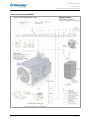
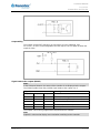
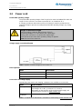
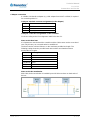
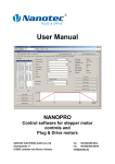
Technical Manual Plug & Drive Motors PD6-N8918 NANOTEC ELECTRONIC GmbH & Co. KG Kapellenstraße 6 D-85622 Feldkirchen b. Munich, Germany Tel. +49 (0)89-900 686-0 Fax +49 (0)89-900 686-50 [email protected] Technical Manual PD6-N8918 Editorial Editorial 2013 Nanotec® Electronic GmbH & Co. KG Kapellenstraße 6 D-85622 Feldkirchen b. Munich, Germany Tel.: Fax: +49 (0)89-900 686-0 +49 (0)89-900 686-50 Internet: www.nanotec.com All rights reserved! MS-Windows 2000/XP/Vista are registered trademarks of Microsoft Corporation. Translation of original handbook Version/Change overview 2 of 33 Version Date Changes 1.0 27.05.2009 New issue 1.1 16.11.2009 Revision 1.2 25.03.2010 CANopen firmware 1.3 03.11.2010 Revision RS485/CANopen 1.4 03.11.2011 External RS-485 logic supply 1.5 25.06.2013 Revision Issue: V 1.5 Technical Manual PD6-N8918 About this manual About this manual Target group This technical manual is aimed at designers and developers who need to operate a Nanotec stepper motor without much experience in stepper motor technology. Important information This technical manual must be carefully read before installation and commissioning of the Plug & Drive motor. Nanotec reserves the right to make technical alterations and further develop hardware and software in the interests of its customers to improve the function of this product without prior notice. This manual was created with due care. It is exclusively intended as a technical description of the product and as commissioning instructions. The warranty is exclusively for repair or replacement of defective equipment, according to our general terms and conditions; liability for subsequent damage or errors is excluded. Applicable standards and regulations must be complied with during installation of the device. For criticisms, proposals and suggestions for improvement, please contact the above address or send an email to: [email protected] Additional manuals Please also note the following manuals from Nanotec: NanoPro User Manual Configuration of controllers with the NanoPro software NanoCAN User Manual Configuration of the CAN communication for CANopencapable controllers with the NanoCAN software Nanotec CANopen reference Comprehensive documentation of the CANopen functions Programming manual Controller programming • Command reference • NanoJ • COM interface The manuals are available for download at www.nanotec.de. Issue: V 1.5 3 of 33 Technical Manual PD6-N8918 4 of 33 Issue: V 1.5 Technical Manual PD6-N8918 Contents Contents Editorial .................................................................................................................................................... 2 About this manual .................................................................................................................................... 3 Contents .................................................................................................................................................. 5 1 Overview ............................................................................................................................... 7 2 Connection and commissioning ...................................................................................... 10 2.1 Connection diagram ............................................................................................................. 10 2.2 Commissioning..................................................................................................................... 12 3 Connections and circuits .................................................................................................. 16 3.1 Signal cable.......................................................................................................................... 16 3.2 Power cord ........................................................................................................................... 18 3.3 RS485 network/CANopen .................................................................................................... 19 3.4 External logic supply ............................................................................................................ 25 4 Operating modes................................................................................................................ 26 4.1 Serial operating modes ........................................................................................................ 26 4.2 CANopen operating modes .................................................................................................. 28 5 Troubleshooting ................................................................................................................. 29 6 Technical data .................................................................................................................... 31 Index ...................................................................................................................................................... 33 Issue: V 1.5 5 of 33 Technical Manual PD6-N8918 Contents 6 of 33 Issue: V 1.5 Technical Manual PD6-N8918 Overview 1 Overview Introduction The Plug & Drive motor PD6-N8918 includes, in addition to the integrated power end stage, a complete, network-capable closed loop speed and positioning control. The PD6-N8918 not only significantly reduces development and installation outlay, but also space and component requirements. It also increases flexibility, system properties and the availability of a complete drive unit. Replacement of existing drive solutions is easy with the mechanical and electrical compatibility with standard motors. Variants The PD6-N8918 is available in the following variants that differ in holding torque, weight and length (see Section 6 “Technical data"): • PD6-N8918S6404 • PD6-N8918M9504 • PD6-N8918L9504 Firmware variants The Plug & Drive motor can be operated with the following firmware variants: • RS485 firmware • CANopen firmware Functions of the PD6-N8918 The Plug & Drive motor PD6-N8918 has the following functions: • Microstep 1/1 – 1/64 Final output stage (0.014° step resolution) • Closed loop current control (sinusoidal commutation via the encoder) • Sequence programs with NanoJ (RS485) • Integrated encoder for rotation monitoring and closed loop current control • RS485/CANopen interface for parameterization and control (USB connection possible via converter cable ZK-RS485-USB) • Network capability with up to 254 motors (RS485) or 127 motors (CANopen) • Easy programming with Windows software NanoPro (RS485) or NanoCAN (CANopen) Issue: V 1.5 7 of 33 Technical Manual PD6-N8918 Overview Closed loop current control (sinusoidal commutation via the encoder): In contrast to conventional stepper motor controllers where only the motor is actuated or the position adjusted via the encoder, sinusoidal commutation controls the stator magnetic field via the rotary encoder as in a servo motor. The stepper motor acts in this operating mode as nothing more than a high pole servomotor, i.e. the classic stepper motor noises and resonances vanish. As the current is controlled, the motor can no longer lose any steps up to its maximum torque. If the controller recognizes that the rotor is falling behind the stator field due to overload, adjustments are made with optimal field angle and increased current. In the opposite case, i.e. if the rotor is running forward due to the torque, the current is automatically reduced so that current consumption and heat development in the motor and controller are much lower compared to normal controlled operation. The integrated programming language NanoJ, based on the Java standard, means complete application programs can be realized on the drivers that can be executed independently without a higher-order controller. The programs can be created, compiled directly and written to the controller with the free NanoJEasy editor. NanoJ is only supported by the RS485 firmware. More detailed information can be found in the separate programming manual. Activation via CANopen It is possible to include the stepper motor controller in a CANopen environment with the PD6-N8918. The connection can be established either via 2 wires of the I/O connection cable or in a customer-specific version also via a Hummel Twintus connector. More detailed information on this can be found in the CANopen reference and in the NanoCAN user manual. In addition, the Plug & Drive motor via CANopen has another safety function: Even when the voltage supply of the PD6-N8918 is interrupted, the processor continues to be supplied with power via the communication line and the position data cannot be lost so that the machine does not need to be referenced after being switched on. Settings The operating behavior of the motor can be set and optimized according to individual requirements by setting the motor-related parameters. The parameters can be set using the NanoPro or NanoCAN software and significantly reduce commissioning time. More detailed information on this can be found in the separate NanoPro or NanoCAN user manual. 8 of 33 Issue: V 1.5 Technical Manual PD6-N8918 Overview Rotation monitoring Even if stepper motors do not lose steps during normal operation, the integrated speed control provides additional security in all operating modes, e.g. against motor stalling or other external sources of error. The monitoring function detects a stalled motor or step loss after tenth of a step at the most (for 1.8° stepper motors with 500 pulses/rotation). Automatic error correction is possible after the drive profile is ended or during the drive. Issue: V 1.5 9 of 33 Technical Manual PD6-N8918 Connection and commissioning 2 2.1 Connection and commissioning Connection diagram Introduction To operate the Plug & Drive Motor, you must implement the wiring according to the following connection diagram. 10 of 33 Issue: V 1.5 Technical Manual PD6-N8918 Connection and commissioning Connection diagram PD6-N8918 Issue: V 1.5 11 of 33 Technical Manual PD6-N8918 Connection and commissioning 2.2 Commissioning Requirements The connection and commissioning of the PD6-N8918 Plug & Drive motor are described below. This section describes the main first steps you need to take to be able to quickly begin working with the PD6-N8918 if you want to work with the NanoPro (RS485) or NanoCAN (CANopen) software from a PC. You will find more detailed information in the separate NanoPro and NanoCAN manuals. If you want to work with a PLC or your own program later, you will find the necessary information in the separate programming manual (RS485) or in the CANopen reference (CANopen). Familiarize yourself with the PD6-N8918 Plug & Drive motor and the relevant NanoPro or NanoCAN control software before configuring the Plug & Drive motor for your application. Selecting the firmware The Plug & Drive motor is always delivered with a firmware that is optimized for RS485. For the operation and configuration of the Plug & Drive motor with a CANopen interface and NanoCAN, you first need to perform a firmware update. To do this, proceed as follows: Step 12 of 33 Action Note 1 Install the NanoPro control software on your PC. See the NanoPro separate manual. Download of www.nanotec.com 2 Connect the PC to the RS485 port of the motor controller according to the connection diagram. Connection diagram, see Section 2.1. 3 In NanoPro open the menu <System / Firmware change / select firmwasre> The following window appears: 4 Select the desired firmware and click on "Open". Issue: V 1.5 Technical Manual PD6-N8918 Connection and commissioning Commissioning with NanoPro (RS485 firmware) Proceed as follows to commission the Plug & Drive motor: Step Issue: V 1.5 Action Note 1 Install the NanoPro control software on your PC. See the NanoPro separate manual. Download of www.nanotec.com 2 Connect the Plug & Drive motor according to the connection diagram. For easier commissioning the ZIB-PDx-N terminal strip that already integrates the SubD connections for RS485 and CANopen can be used. Connection diagram, see Section 2.1. Detailed information on connections can be found in Section 3. 3 Switch on the operating voltage (24 V DC ... 48 V DC). CAUTION! An operating voltage > 50 V will destroy the output stage! • Follow the information in Section 3.2. 4 If necessary, install the driver for the converter cable ZK-RS485-USB. Download www.nanotec.com in the Accessories/Converter menu item 5 Connect the Plug & Drive motor with the USB port of your PC. Use the converter cable ZK-RS485-USB. Connection via the RS232 interface is not possible. Order number: • ZK-RS485-USB 6 Start the NanoPro software. The NanoPro main menu appears. 7 Select the <Communication> tab. 8 In the field "Port", select the COM port to which the PD6-N8918 is connected. The number of the COM port to which the Plug & Drive Motor is connected can be found in the device manager of your Windows PC (System Control/System/Hardwar e). 13 of 33 Technical Manual PD6-N8918 Connection and commissioning Step Action 9 Select the "115200 bps" entry in the "Baudrate" selection field. 10 Check the current setting using the motor data sheet on the <Motor Settings> tab. Presettings: • • 14 of 33 Phase current: 50% (current level) Phase current during idle: 25% (idle current) Note Under no circumstances may the current be set to a value higher than the rated current of the motor. 11 Select the <Movement Mode> tab. 12 Click on the <Test Record> button to carry out the pre-set travel profile. The connected motor operates with the pre-set travel profile (default travel profile after new installation). 13 You can now enter your required settings. For instance, you can enter a new travel profile. See the NanoPro separate manual. Issue: V 1.5 Technical Manual PD6-N8918 Connection and commissioning Commissioning with NanoCAN (CANopen firmware) Proceed as follows to commission the Plug & Drive motor with the CANopen firmware. More detailed information can be found in the separate NanoCAN manual. Step Action Note 1 Install the NanoCAN control software on your PC. Download of www.nanotec.com 2 Connect the Plug & Drive motor according to the connection diagram. Connection diagram, see Section 2.1. Detailed information on connections can be found in Section 3. 3 Switch on the operating voltage (24 V DC ... 48 V DC). CAUTION! An operating voltage > 50 V will destroy the output stage! • Follow the information in Section 3.2. 4 Install and configure your CANopen adapter. 5 Start the NanoCAN software. 6 Select the desired node ID, the baud rate and, if necessary, the CAN card in the <Configuration & NMT> tab. 7 Check the current setting using the motor data sheet. Presettings: • Phase current: 50% (current level) Details can be obtained from the manufacturer of the CANopen adapter. Under no circumstances may the current be set to a value higher than the rated current of the motor. • Phase current during idle: 25% (idle current) Issue: V 1.5 8 Select the desired operating mode (e.g. PP mode) in the <Drive Modes> tab. 9 Click on the <Power on> button. 10 Enter the desired target position in the "target" field. 11 Click on the <Start> button. 15 of 33 Technical Manual PD6-N8918 Connections and circuits 3 3.1 Connections and circuits Signal cable Introduction An overview of the assignments can be found in the connection diagram in Section 2.1). This section looks in detail at the assignment, functions and circuits of the signal cable. Pin assignment Name Wire color Input 1 BK Input 2 VT Input 3 GY/PK Input 4 RD/BU Input 5 WH/GN Input 6 BN/GN Analog Input WH/BU Output 1 WH/YE Output 2 YE/BN Output 3 WH/GY RS485 Tx + GY RS485 Tx – PK RS485 Rx – YE RS485 Rx + GN CAN + BN CAN – WH Signal GND (Com) GY/BN GND BL + RS/BN GND Logic RD Vcc Logic WH/PK Function of the inputs All digital inputs – with the exception of the "Clock" input in the clock directional mode – can be freely programmed using the NanoPro software (RS485) (e.g. as a limit position switch, enable, etc.) and can be used for sequential control with NanoJ. All inputs can be configured for “active-high" (PNP) or “active-low" (NPN) with NanoPro. Input circuits All inputs (apart from the "Analog In" input) are electrically isolated by optocouplers from the supply voltage of the PD6-N8918 and designed for 5-24 V input signals at an input current of 8 mA. Note: The voltage must not exceed 24 V. It should drop below 2 V for safe switching off and be at least 4.5 V for safe switching on. 16 of 33 Issue: V 1.5 Technical Manual PD6-N8918 Connections and circuits Output wiring The outputs are MosFET outputs in an Open-Drain circuit (0 switching, max. 24 V/1.5 A). An LED can be integrated to test the output. The LED lights up when the output is active. Signal states at the outputs (RS485) Note: In the CANopen firmware, the status of the controller is not displayed at the outputs. The following table shows the possible signal states at the outputs 1 to 3: Signal states Output 3 1 Meaning Output 2 Output 1 0 0 Rotation monitoring (error) or limit switch 0 1 Motor idle (waiting for new command) 1 0 Busy (control processing last command) 1 1 Reference point or zero point reached Overtemperature The outputs can be freely programmed using the NanoPro software. Note: Output 3 is also used to display errors and when switching on the controller. Issue: V 1.5 17 of 33 Technical Manual PD6-N8918 Connections and circuits 3.2 Power cord Permissible operating voltage The permissible operating voltage of the Plug & Drive motor PD6-N8918 lies within the range of +24 to +48 V DC and must not exceed 50 V or undershoot 21 V. A charging condenser with minimum 4700 µF (10000 µF) must be provided for the operating voltage to prevent exceeding the permissible operating voltage (e.g. during braking). Danger of electrical surges Connect charging condensor with minimum 4700 µF! An operating voltage > 50 V will destroy the output stage! Mixing up the connections can destroy the output stage! Never disconnect the motor when operating voltage is applied! Never disconnect lines when live! Voltage supply connection diagram Note: Complete connection diagram, see Section 2.1. Pin assignment Name Wire number VCC 1 GND 2 PE GN/YE Accessories for voltage supply Appropriate power packs and charging condensers are available as accessories: Name Order identifier Power pack NTS-xxV-yA (xx=voltage: 24 or 48 V, y=current: 2.5, 5 or 10 A) Information on the selection of the required power supply unit can be found in our FAQ on www.nanotec.com. Charging condenser Z-K4700 or Z-K10000 Note: A complete set of datasheets is available for downloading at www.nanotec.com. 18 of 33 Issue: V 1.5 Technical Manual PD6-N8918 Connections and circuits 3.3 RS485 network/CANopen PD6-N8918 in a network Up to 254 (RS485) or 127 (CANopen) Plug & Drive motors can be actuated in a network from a PC or PLC. These network connections are set up via the RS485/CANopen interface. Two-wire operation RS485 To enable RS485 two-wire transmission capability, all bus stations must have a direction control. An "intelligent" converter enables two-wire operation of the PD6-N8918 as it automatically switches to transmit operation when receiving a start bit at the RS232 interface and returns to reception standby at the end of the stop bit. This solution requires no software support. We can recommend the ICP-7520 converter, for example, that is available from Schuricht. Talk to our Technical Hotline if you require support for this. Issue: V 1.5 19 of 33 Technical Manual PD6-N8918 Connections and circuits Circuit diagram RS485 network 20 of 33 Issue: V 1.5 Technical Manual PD6-N8918 Connections and circuits CANopen connection A suitable CAN interface adapter (e.g. USB adapter from IXXAT or PEAK) is required for connecting with a PC. CANopen standard connector assignment (on the adapter) Pin no. Name 2 CAN low 3 CAN GND 7 CAN high CANopen connection assignments on the controller Circuit according to the "Pin assignment" table in Section 3.1. Notes on the baud rate It is important to note that both the controller and the CAN master use the same baud rate. Only this way can communication be established. The baud rate has a direct influence on the maximum possible bus length. The following setting shows the possible baud rates and the associated maximum permissible bus lengths. Baudrate 1 MBaud Bus length 40 m 500 kBaud 130 m 250 kBaud 270 m 125 kBaud 530 m 50 kBaud 1300 m 20 kBaud 3300 m Notes on the bus termination With CAN, the bus termination is handled by two 120 Ohm resistors on both ends of the bus. Issue: V 1.5 21 of 33 Technical Manual PD6-N8918 Connections and circuits Setting the RS485 module address Hardware setting The RS485 module address can be set by hardware via two HEX coded switches on the printed circuit board. Switch 1 for address 1...15 Switch 1 for address 1...15 Switch 2 for address 16...32 Switch 2 for address 16...32 The 1st digit is set with switch 1 (left), the 16th digit of the address is set with switch 2 (right). Addresses 0x00 and 0x80 signalize that the address can be set in the software. For address settings via the HEX coded switches that are larger than 128, the value 128 must be subtracted from the set value. Rotary switch value (decimal) 0 1-127 128 129-255 Rotary switch value (hex) 0x00 0x01-0x7F 0x80 0x81-0xFF Node ID of rotary switch value Node ID from EEPROM 22 of 33 X X X-128 X Issue: V 1.5 Technical Manual PD6-N8918 Connections and circuits Example: Module address Switch 1 (left) Switch 2 (right) Software setting 0 0 1 1 0 2 2 0 ... ... ... 15 F 0 16 0 1 17 1 1 ... ... ... 32 0 2 ... ... ... 64 0 3 ... ... ... 80 0 5 ... ... ... 96 0 6 ... ... ... 112 0 7 ... ... ... 127 F 7 Software setting 0 8 1 (129-128) 1 8 2 (130-128) 2 8 … … … 15 (143-128) F 8 … … … 32 (160-128) 0 A … … … 96 (224-128) 0 E … … … 126 (254-128) E F 127 (255-128) F F In case of the settings 0x00 and 0x80, between 1 and 255 can be set via the software addresses. Address values higher than 127 therefore can only be set via the software. When the power supply is applied, the controller checks which address is set with the 2 hardware switches. This hardware address is then adopted. After the address is changed, the power supply must be briefly switched off and on again. Software setting Both switches are set to 0 at delivery. With this setting, the address can be changed in the software as of firmware status 04.12.2008 or later. See the NanoPro separate manual. Issue: V 1.5 23 of 33 Technical Manual PD6-N8918 Connections and circuits Setting the CANopen module address There are two basic ways of setting the CANopen node ID and the baud rate: • Hardware setting: via rotary switches on the controller • Software setting: With NanoCAN, see separate manual for NanoCAN. To be able to make a software setting with NanoCAN, a certain value must be set on the rotary switches of the controller; see the following table: Rotary switch value dec (hex) Node ID 0 (0x00) from EEPROM 1 - 127 (0x01 - 0x7F) = rotary switch value 128 (0x80) from EEPROM 129 - 255 (0x81 - 0xFF) = rotary switch value minus 128 Baudrate = 1 MBaud from EEPROM Note:The rotary switches must be set to the desired value before the controller is switched on since this value is only read in when the controller is restarted. The rotary switches can be used to set a two-digit hexadecimal number (0x00 to 0xFF): • Right-hand rotary switch: 16's place (e.g. 0xF0) • Left-hand rotary switch: 1's place (e.g. 0x0F) Example 1: If the right-hand rotary switch is set to 2 and the left-hand rotary switch is set to 1 (0x21), this results in a number equivalent to the decimal number 33 (= 2*16 + 1*1). In this case, the node ID is set to 33 on the hardware. The baud rate is set to 1 MBaud. Example 2: If the right-hand rotary switch is set to 8 and the left-hand rotary switch is set to 0 (0x80), this results in a number that is equivalent to the decimal number 128 (= 8*16 + 0*1). In this case, the node ID and baud rate are read out of the EEPROM. 24 of 33 Issue: V 1.5 Technical Manual PD6-N8918 Connections and circuits 3.4 External logic supply With the Plug & Drive motor you can use the additional safety feature of the separate logic supply. Even when the voltage supply of the PD6-N8918 is interrupted, the processor continues to be supplied with power via the communication line and the position data cannot be lost so that the machine does not need to be referenced after being switched on. More detailed information on this can be found in the CANopen reference and in the NanoCAN user manual. Notes on operating with the RS485: Since the firmware version 04.03.11, the external logic supply also functions for RS485. If the operating voltage is disconnected, the controller switches "Not ready" status and shows the error state "Undervoltage". Issue: V 1.5 25 of 33 Technical Manual PD6-N8918 Operating modes 4 4.1 Operating modes Serial operating modes Introduction Depending on the travel profile, the motor can be operated using different operating modes. Due to the great capacity and functions available, it offers designers and developers a rapid and simple method of resolving numerous drive requirements with less programming effort. Select the required operating mode for each drive profile and configure the controller according to your requirements. More detailed information can be found in the separate NanoPro manual. Overview of operating modes and their areas of application Operation mode Application Relative positioning Use this mode when you wish to travel to a specific position. The motor travels according to a specified drive profile from a Position A to a Position B. Absolute positioning 26 of 33 Internal reference run During the internal reference run, the motor travels to an internal reference point at the set minimum speed (index mark of encoder, only in combination with an encoder). External reference run During an external reference run, the motor travels to a switch connected to the reference input. Speed mode Use this mode when you wish to travel with a specific speed (e.g. a conveyor belt or pump speed). In the speed mode, the motor accelerates with a specified ramp from the starting speed (start frequency "V Start") to the specified maximum speed (maximum frequency "V Normal"). Several inputs enable the speed to be changed onthe-fly to different speeds. Flag positioning mode The flag positioning mode offers a combination of the speed and positioning modes. The motor is initially operated in speed mode; when a trigger point is reached, it changes to the positioning mode and the specified setpoint position (relative to the trigger position) is approached. This operating mode is used for labeling, for example: the motor first travels with the set ramp to the synchronous speed of the conveyed goods. When the labels are detected, the preset distance (position) is traveled to apply the labels. Issue: V 1.5 Technical Manual PD6-N8918 Operating modes Operation mode Application Clock direction mode, left Use this mode when you wish to operate the motor with a superordinate controller (e.g. CNC controller). In the clock direction mode, the motor is operated via two inputs with a clock and a direction signal from a superordinate positioning control (indexer). Depending on the mode selected (Int. Ref./Ext. Ref.), the internal and external reference runs are supported. Clock direction mode, right Clock direction mode Int. Ref. Clock direction mode Ext. Ref. Analog and joystick mode The motor is controlled in this operating mode simply with a potentiometer or a joystick (–10 V to +10 V). Use this mode if you want to use the motor in a simple application: • Setting a specific speed, e.g. via an external potentiometer, • Traveling synchronously with a superordinate controller with analog output (–10 V to +10 V). Analogue positioning mode Use this mode when you wish to travel to a specific position. The voltage level on the analog input is proportional to the required position. Torque mode Use this mode when you require a specific output torque independent of the speed as is the case in typical winding and unwinding applications. The maximum torque is specified via the analog input. Selecting the operating mode in NanoPro Issue: V 1.5 27 of 33 Technical Manual PD6-N8918 Operating modes 4.2 CANopen operating modes Introduction The motor can be operated using a total of 5 different operating modes in CANopen mode. More detailed information can be found in the separate NanoCAN manual. Overview of operating modes and their areas of application Operation mode Application Positioning Mode (PP Mode) Use this mode if you want to use the motor for positioning. The motor moves from A to B with the set parameters (ramp, speed, etc.). Speed Mode (Velocity Mode) Use this mode when you wish to travel with a specific speed (e.g. a conveyor belt). Reference run (Ref. Mode/Homing Mode) Use this mode to reference the motor (internal/external/on block). Interpolated Position Mode Use this mode with a superordinate path control. Torque Mode Use this mode to specify a defined torque. Selecting the operating mode in NanoCAN In the <Drive Modes> tab the operating mode can be selected. When the tab is activated, the corresponding SDO is immediately written to the controller to activate the (possibly previously) selected operating mode. 28 of 33 Issue: V 1.5 Technical Manual PD6-N8918 Troubleshooting 5 Troubleshooting Troubleshooting procedure Proceed with care during troubleshooting and error rectification to avoid damaging the Plug & Drive Motor. Danger of electrical surges An operating voltage > 50 V and incorrect connections can destroy the end stage. Never disconnect the motor when operating voltage is applied! Never disconnect lines when live! Possible errors in serial mode Issue: V 1.5 Error Possible cause Rectification Plug & Drive Motor is not ready Data transfer to PD6-N8918 is not possible (communication error): Incorrect COM port selected. On the <Communication> tab, select the PC port on the PC to which you have connected the PD6-N8918 (e.g."COM-1"). The port used can be found in the device manager of your PC. Communication cable not connected or interrupted (incorrect RS485 converter used). Use the recommended RS485 converter from Nanotec: • Order identifier: ZK-RS485-USB A non-existent motor number (module number) is set. Set the correct module address. See the separate manual on NanoPro. The voltage supply to the PD6-N8918 is interrupted. Check voltage supply, switch on if necessary. Another open program is blocking the COM port to which the PD6-N8918 is connected. Close down other programs on your PC. Inadmissible data was sent to the Plug & Drive motor during the output of a travel profile. Click on the <Yes> button to stop the travel profile. The PD6-N8918 switches to the "Ready" status. The data can then be resent to the Plug & Drive Motor. Transmission error The data transfer to the PD6- Check that the motor connection is N8918 is disturbed (transmitter correctly wired. or receiver are disturbed). We recommend using the following Nanotec converters: • ZK-RS485-USB Position error The motor cannot reach the Click the <Yes> button in the error position or the limit switch was message; the error is reset. overrun. 29 of 33 Technical Manual PD6-N8918 Troubleshooting Possible errors in CANopen mode Error Possible cause No The wrong node ID has been communication set. with the controller Transmission error 30 of 33 Rectification On the <Configuration & NMT> tab in NanoCAN, select the node ID that is set on the rotary switches of the controller. The power supply is interrupted. Check voltage supply, switch on if necessary. The communication cable is not connected or is interrupted. Check all connections, especially the terminal resistances. CAN bus incorrectly terminated with 120 Ohm. Ideally, terminate the bus on both ends with 120 Ohm. Data transmission is disturbed Switch the power supply off and on (sporadically). again. Issue: V 1.5 Technical Manual PD6-N8918 Technical data 6 Technical data Electrical connections Operating voltage Vb DC 24 V to 48 V ±4% Max. phase current Adjustable up to max. 12 A/phase Continuous current 7.5 A/phase Current drop Adjustable 0 to 80% of rated current Interfaces RS485 (4-wire) • 115200 bps (adjustable) • 1 start bit, 8 data bits, 1 stop bit • No parity CAN bus (CANopen) • 1 MBaud (adjustable) Type of connection PG gland, cable length = 2 m Hummel Twintus connector Motor parameters Issue: V 1.5 Step resolution Full Step Half Step Quarter Step Fifth Step Eighth Step Tenth Step 16th step 32nd Step 64th Step Feed rate Adaptive microstep (1/128) Step angle 1.8° Operating modes Position Speed Flag position Clock direction Analog Joystick Torque Step frequency 0 to 50 kHz in clock direction mode 0 to 25 kHz in all other modes Position monitoring Automatic error correction up to 0.18° (depending on encoder resolution) 31 of 33 Technical Manual PD6-N8918 Technical data Inputs and outputs Inputs 6 optocouplers, 5 – 24 V • Safe switch off: max. 2 V • Safe switch on: min. 4.5 V Signal delay time: • Inputs 1 to 5: • Input 6: Outputs 120 µs 10 µs 3 MosFET outputs • Open-Drain (0 switching, max. 24 V/1.5 A) • Signal delay time: output 1/2: H 12 µs (with 10 k©Pull-Up at 24 V) Protective circuits Overvoltage and undervoltage Protective circuit for voltages > 50 V or < 21 V Max. heat sink temperature Approx. 67 °C Max. ambient temperature 0 to 40 °C Holding torque, weight and dimensions Variants Holding torque (Nm) Weight (kg) Length “L" (mm) PD6-N8918S6404 3.2 1.7 89 PD6-N8918M9504 5.94 3.4 121 PD6-N8918L9504 9.33 3.95 151 A complete set of datasheets is available for downloading at www.nanotec.com. 32 of 33 Issue: V 1.5 Technical Manual PD6-N8918 Index Index A O Accessories for voltage supply ...................... 18 Operating modes .......................................... 26 CANopen ................................................... 28 C CANopen .............................................8, 15, 19 Closed loop current control.............................. 8 serial .......................................................... 26 Operating voltage.......................................... 18 Output circuits ............................................... 17 Commissioning .............................................. 12 Connection diagram ...................................... 11 D P Pin assignment Power cord ................................................ 18 Dimensions .................................................... 32 Signal cable ............................................... 16 E Power cord .................................................... 18 Encoder ........................................................... 9 R F Rotation monitoring ......................................... 9 Firmware .................................................... 7, 12 RS485 network ............................................. 19 Functions ......................................................... 7 S H Signal cable .................................................. 16 Holding torque ............................................... 32 T I Two-wire operation ....................................... 19 Input circuits .................................................. 16 V Inputs and outputs ......................................... 16 Variants ........................................................... 7 L Voltage supply .............................................. 18 Logic supply ................................................... 25 W N Weight ........................................................... 32 NanoJ .............................................................. 8 Issue: V 1.5 33 of 33